

Two operators. Same 0.125 stainless. Same 0.118 punch tip. One makes a clean 0.140 inside radius. The other cracks the outside and measures 0.180.
They both point at the punch.
I’ve stood between those two machines more times than I care to admit, and the steel never lies. If the punch were the mold, those parts would match. They don’t. So something else is running the show.
You’ve been told the punch tip radius equals your inside bend radius. It feels right. The nose looks like a mold. You press metal into it. Shape meets shape.
But in air bending, the sheet never fully wraps that punch tip. It’s suspended between three contact points: punch nose and two die shoulders. The bottom of the V is air. That curve you’re proud of is floating, not stamped.
Treating the punch like a mold in air bending is like trying to measure a board while it’s balanced across two sawhorses and pretending the floor underneath controls the sag. The floor isn’t touching it. Neither is the bottom of your die.
If the punch isn’t actually molding the metal, what is controlling the curve forming between those die shoulders on your machine right now?
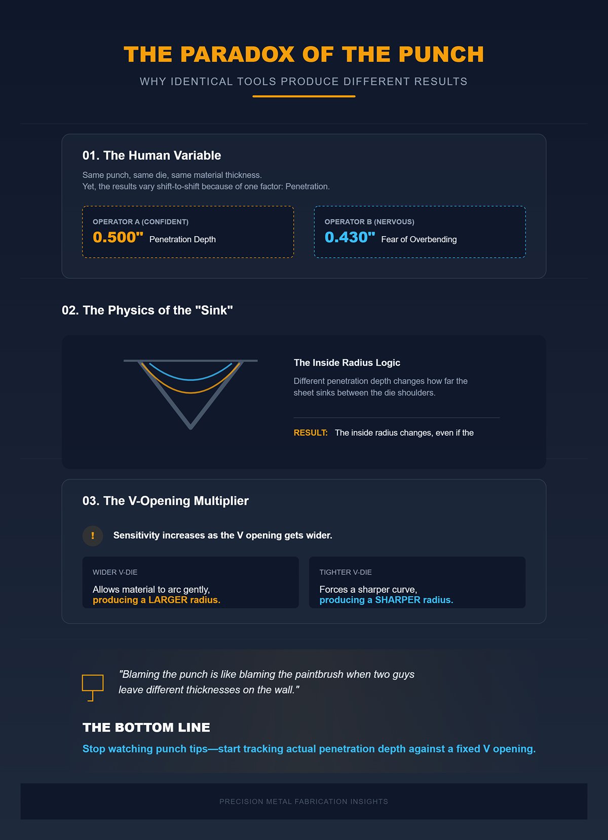
Picture this: same punch, same die, same material thickness. Operator A penetrates 0.500 into the V. Operator B goes 0.430 because he’s nervous about overbending.
Different penetration depth changes how far the sheet sinks between the die shoulders. That changes the inside radius. The punch didn’t change. The die opening didn’t change. The depth did.
And depth sensitivity increases as the V opening gets wider. A wider V lets the material arc more gently, producing a larger radius. A tighter V forces a sharper curve. That’s why one lower V-die can run multiple punches and still produce predictable radii—because the die width is the reference.
Ignoring that is like blaming a paintbrush when two guys using the same roller leave different thickness on the wall; it’s the pressure and distance that changed.
So when your parts vary shift to shift, are you watching punch tips—or are you tracking actual penetration depth against a fixed V opening?
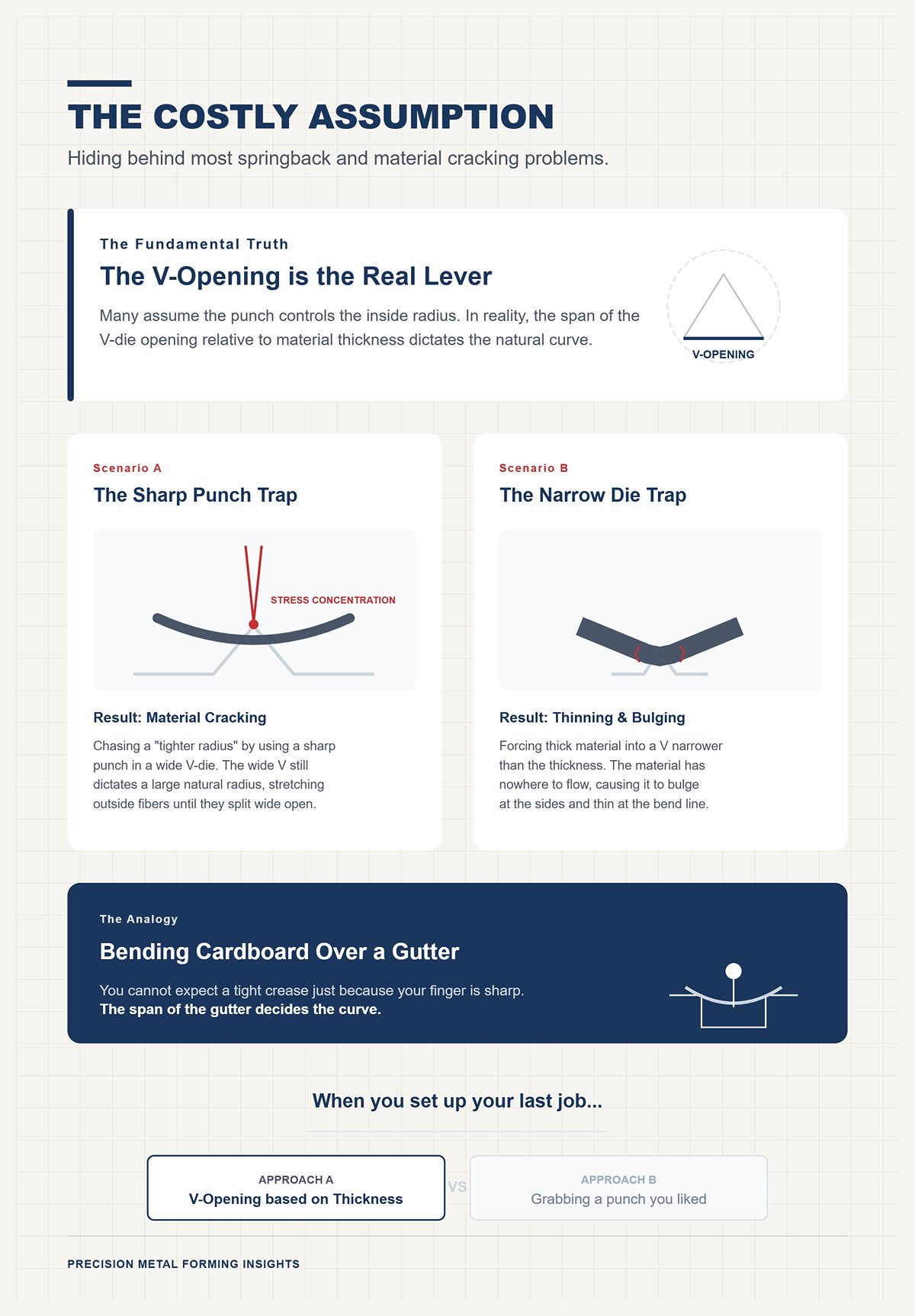
I’ve seen 304 stainless split wide open because someone chased a “tighter radius” by swapping to a sharper punch while leaving a wide V-die in place.
The wider V still dictated a large natural radius. The sharp punch only concentrated stress at the tip. The outside fibers stretched harder than they needed to. Crack.
On the flip side, I’ve watched guys force thick mild steel into a V narrower than the material thickness, trying to “match the punch.” The material had nowhere to flow. It bulged at the sides and thinned at the bend line.
That assumption—that the punch controls the inside radius—drives both mistakes. It hides the real lever: V opening relative to material thickness.
It’s like trying to bend heavy cardboard over a wide gutter and expecting a tight crease just because your finger is sharp. The span decides the curve.
When you set up your last job, did you choose the V opening based on thickness and target radius—or did you start by grabbing a punch you liked?
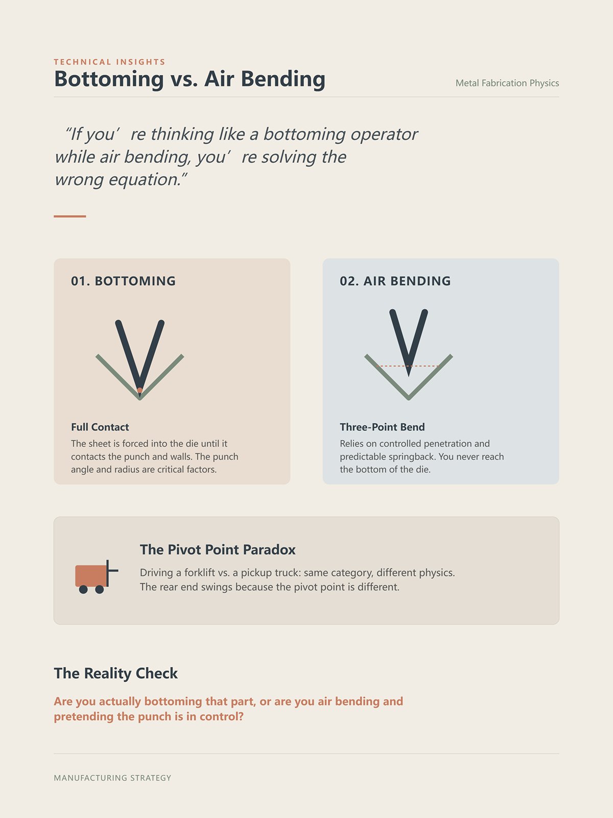
Now let’s be fair. In bottoming, the sheet is forced into the die until it contacts the punch and the die walls. Full contact. The metal conforms. The punch angle and radius matter a lot more.
Different game.
In air bending, you never reach the bottom. You rely on controlled penetration and predictable springback from a three-point bend. If you’re thinking like a bottoming operator while air bending, you’re solving the wrong equation.
That’s like driving a forklift and steering it like a pickup truck—the rear end swings because the pivot point is different. Same machine category. Different physics.
Before you touch another punch, answer me this: are you actually bottoming that part, or are you air bending and pretending the punch is in control?
You’ve got 0.125 stainless on the rack and you want a clean 0.125 inside radius. You’re staring at your tool cabinet thinking, Which V opening gets me there? Good. That’s the right question.
Last winter we ran 0.250 mild steel through two different dies. Same punch. One was a 2-inch V. The other was a 3-inch V. Nothing else changed. The 2-inch V consistently produced about a 0.320 inside radius. The 3-inch V? Closer to 0.500. Same punch nose. Same operator. Same press brake.
The only thing that moved was the distance between the die shoulders.
That’s not a coincidence. That’s the mechanism.
Think of the sheet like a plank laid across two sawhorses. The punch pushes down in the middle, sure—but the curve forms because of the span between the sawhorses. Widen the span, the sag gets gentler. Narrow it, the curve tightens. The punch isn’t carving the radius. It’s forcing the sheet to arc between two fixed supports.
If the span is the real driver, why are you still opening your setup by choosing a punch instead of a die?
I’m going to clean up a common mental picture before it costs you parts.
The sheet does not fully wrap the punch and then magically “float.” In true air bending, it’s in three-point contact the whole time: punch tip and both die shoulders. What changes is who’s doing the shaping.
Early in the stroke, the punch tip dominates because the material hasn’t yielded yet. You’re still in elastic deformation—just flexing the sheet. Once you pass yield strength, plastic deformation begins. Now the metal flows, and the die shoulders become the fixed anchors that define the arc.
That transition is subtle. No dramatic moment. But mechanically, it’s everything.
The bottom of the V never touches the sheet. There is air under that bend line. The radius forms because the material is being stretched over a span. The punch only supplies force and angle; the shoulders supply geometry.
And here’s where operators get fooled: if you swap to a sharper punch in the same V opening, the measured inside radius barely changes. What does change is stress concentration at the bend line. You feel more tonnage spike. You see more cracking in harder alloys. But the arc between the shoulders stays governed by the V width.
If your parts are cracking, are you tightening the punch nose—or questioning whether your V opening is too wide for that alloy’s elongation?
Now we get practical.
For mild steel in air bending, the natural inside radius will land at roughly 16–20% of the V-die opening. Stainless tends to run a bit larger. Softer aluminum can run smaller because it compresses more on the inside of the bend.
That’s not folklore. It comes from how the neutral axis shifts during plastic deformation. Softer materials allow more inside compression, tightening the radius for the same span. Harder materials resist compression, so the arc relaxes outward.
Before we go any further—test this on scrap first.
If you’re targeting a 0.125 inside radius in mild steel, and you assume 20% as a working number:
Inside Radius ≈ 0.20 × V Opening V Opening ≈ Inside Radius ÷ 0.20
So:
0.125 ÷ 0.20 = 0.625 V opening.
You’d reach for a 5/8 V.
Will it land exactly at 0.125? No. Material batch, grain direction, and yield strength tweak it. But you’ll be close before the ram even moves. That’s control.
Now contrast that with guessing a punch radius and hoping the die cooperates.
And about that claim you’ve heard—that three-point bending gives a “consistent radius regardless of thickness variation.” Within reason, yes. Small thickness variation doesn’t radically change the arc because the span is fixed. But double the thickness in the same V and you change strain distribution and required penetration. The die still dictates the geometric possibility; the material dictates how gracefully it fills that possibility.
So when you quote a job, are you calculating backward from target radius to V opening—or are you dialing penetration and praying?
Let’s go back to those Two operators.
Same die. Same punch. One hits 88 degrees. The other hits 92. They argue about radius. They’re looking in the wrong place.
Punch depth controls angle because angle depends on how far the sheet is driven between the shoulders. Deeper penetration decreases the included angle. Shallower penetration increases it. Modern CNC brakes even monitor force rise as yield is crossed, adjusting stroke to hit angle repeatably despite material variation.
But in air bending, the sheet never fully wraps that punch tip. The radius is born from the span. Changing depth rotates the legs around that arc; it doesn’t redraw the arc itself.
If you’re thinking like a bottoming operator while air bending, you’re solving the wrong equation.
Drive deeper and you’ll change angle and springback behavior. Swap dies and you’ll change radius. Mix those up and you’ll chase ghosts all shift.
Angle is depth. Radius is V opening. Material modifies both.
So stand at your machine right now and tell me—what V opening is in the bed, what percentage are you assuming for that material, and did you choose it before or after you grabbed the punch?
You’ve got 3 mm mild steel on the table. Print calls for a clean 90. No inside radius specified. The apprentice grabs a 16 mm V because it “looks right.” First part springs back to 94 degrees. Second part cracks at the grain line when he swaps punches trying to fix it.
That’s what guessing looks like.
If the die opening dictates the radius, then die selection can’t be a vibe. It has to be a calculation. For standard mild steel in air bending, 8× material thickness is the baseline because it lands you in the mechanical sweet spot—reasonable tonnage, predictable springback, and a natural inside radius around 20% of that opening.
Before we go any further—test this on scrap first.
For mild steel in air bending:
Inside Radius ≈ 0.20 × V opening If V opening = 8 × thickness
Then: Inside Radius ≈ 0.20 × (8t) = 1.6t
So 3 mm steel in a 24 mm V will naturally form about a 4.8 mm inside radius.
That’s not folklore. That’s geometry and strain distribution working together.
You want control? You start with the die, not the punch. So when you load 3 mm steel, are you reaching for a 24 mm V automatically—or are you still eyeballing what’s already in the rack?
Walk through any job shop. You’ll see racks labeled 6t, 8t, 10t. There’s a reason 8t is the one that lives in the machine.
At 8× thickness, mild steel bends in air without forcing the inside fibers into excessive compression or stretching the outside fibers past their elongation limit. It distributes strain through the cross section in a way that keeps the neutral axis shift predictable. That’s why angle repeatability improves. That’s why cracking is rare in low-carbon steel at this ratio.
Think of the sheet like a plank laid across two sawhorses. Move the sawhorses too close and the plank kinks sharply. Move them too far apart and it barely sags. Eight times thickness puts those sawhorses at a spacing where the bend forms cleanly without fighting the material.
Industry charts give a workable range of 6× to 12× thickness for air bending mild steel. Eight isn’t magic. It’s mid-range. It balances force, radius, and springback. That’s why it became the default.
But default doesn’t mean universal. What happens when you squeeze that span tighter—or stretch it wider?
Let’s stay with that same 3 mm sheet.
At 6×, you’re in an 18 mm V. Your natural inside radius drops toward about 3.6 mm. Looks nice and tight. But your tonnage climbs fast because the material is being forced into a tighter arc. Outside fibers stretch harder. Springback increases because you’ve driven the stress higher.
On the floor, that means more ram force, more deflection, and more variation from left to right unless you’ve got crowning dialed in.
Now jump to 12×—a 36 mm V. Natural radius heads toward 7.2 mm. Tonnage drops. Easy press. But angle control gets touchier because penetration depth changes more for small angle differences. And your flange length requirement grows, which we’ll get to.
This is where operators get themselves in trouble. They chase a smaller radius by shrinking the die without checking tonnage or material ductility. Or they open the die to reduce force and wonder why the radius ballooned.
Eight times thickness keeps you in the middle lane. Six pushes strain. Twelve relaxes it.
So when you deviated from 8× last time, did you calculate why—or were you reacting to what the last operator left in the machine?
| Factor | 6× (18 mm V) | 8× (24 mm V) | 12× (36 mm V) |
|---|---|---|---|
| Sheet Thickness Example | 3 mm | 3 mm | 3 mm |
| Natural Inside Radius | ~3.6 mm (tight) | ~4.8 mm (balanced) | ~7.2 mm (larger) |
| Tonnage Requirement | High | Moderate | Low |
| Material Strain | Increased strain on outside fibers | Controlled strain | Reduced strain |
| Springback | Higher due to increased stress | Predictable | Lower stress but more angle sensitivity |
| Ram Force & Deflection | More force, more potential deflection | Stable and manageable | Easier on press |
| Angle Control | More stable once set | Balanced control | More sensitive to penetration depth changes |
| Flange Length Requirement | Shorter flange possible | Standard flange requirement | Requires longer flange |
| Operational Risk | Risk of overloading, variation without proper crowning | Safe middle ground | Risk of oversized radius and angle inconsistency |
| Overall Effect | Pushes material strain | Optimal balance | Relaxes strain but reduces control |
Now take 3 mm 304 stainless. Same thickness. Same 24 mm V.
You won’t get the same 4.8 mm radius you saw in mild steel. Stainless has higher tensile strength and less ductility. It resists inside compression. The neutral axis shifts less. The bend relaxes outward. Your radius grows—maybe 22–25% of the V instead of 20%.
That’s why the “rule of eight” cracks stainless when you get greedy.
Shops bending thicker stainless plate often move to 10× or even 12× thickness. Not because they want a larger radius—but because the material won’t tolerate the tighter strain from a narrow die. You’re trading radius size for survival.
Aluminum goes the other direction. Softer alloys compress more on the inside. In some cases you can run 6× and still avoid cracking, especially in 5052. Try that with 304 and you’ll be sweeping parts off the floor.
The multiplier isn’t fixed. It shifts with tensile strength and elongation. Harder material? Open the die. Softer material? You can close it—within reason.
When you load stainless, are you still thinking “8× because that’s what we do,” or are you adjusting the span because the alloy demands it?
Let’s say the math says 24 mm V for your 3 mm mild steel. Clean. Predictable. Perfect.
Now look at the print. Flange length is 15 mm.
Minimum flange length for air bending is roughly 0.7 × V opening. For a 24 mm V, that’s about 16.8 mm.
Your 15 mm flange won’t even sit flat on the die shoulders. It’ll fall into the V. You physically cannot make that bend with the “correct” die.
So you drop to an 18 mm V. Now minimum flange is about 12.6 mm. It fits. But your tonnage goes up and your inside radius shrinks. Maybe that’s acceptable. Maybe it cracks at the grain.
This is where theory meets steel.
There’s also machine capacity. Narrower dies spike tonnage per foot. If your brake is rated at 100 tons and the job needs 120 in a 6× die, the “perfect” radius isn’t worth blowing seals and ram guides.
The multiplier is a starting point. Then you check flange length. Then you check tonnage. In that order.
So before you ever think about punch radius, tell me: what’s your flange length, what’s your brake rated for at that die width, and does your chosen V physically support the part—or are you about to force the wrong setup and blame the material?
You’ve checked the print. Thickness, alloy, grain direction. You ran the 8× baseline, adjusted for stainless, verified flange length against 0.7 × V, confirmed tonnage against the brake chart. The die is chosen, locked, and seated.
Now you’re staring at the punch rack.
Two operators will stand in front of that rack and make two different decisions. One grabs a punch with a nose radius close to the print’s inside radius, thinking he’s matching a mold to a cavity. The other grabs an acute punch—sharper than 90 degrees—because he knows he’s chasing angle, not radius. Same die. Same material. Different understanding.
Here’s what’s physically happening. In air bending, the sheet touches in three places: punch tip above, die shoulders below. That’s it. The metal never fully wraps the punch, never seats in the bottom of the V. It behaves like a plank laid across two sawhorses—the die shoulders—while the punch only pushes it down in the middle; the spacing of the sawhorses determines the curve. The punch cannot pull those sawhorses closer together. It cannot shrink the radius the die opening has already dictated.
But in air bending, the sheet never fully wraps that punch tip.
So what is the punch actually doing? It is driving penetration depth, and penetration depth sets angle. The deeper the ram, the tighter the angle—until springback steals some of it back. The punch is an angle tool and a clearance tool. Not a radius mold.
If you’re thinking like a bottoming operator while air bending, you’re solving the wrong equation.
Before we go any further, look at your machine: what punch angle is sitting over that die right now—and is it chosen to control angle, or are you still trying to “match” a radius that the die has already locked in?
Take 3 mm mild steel in a 24 mm V. You know from experience the natural inside radius will land around 4.8 mm. You program a 90-degree bend.
You hit it.
The part comes out at 92 degrees.
That’s springback—the elastic recovery after the load is removed. The outer fibers were stretched, the inner compressed. When you release pressure, some of that strain relaxes and the angle opens.
Now watch what happens if you’re using a 90-degree punch to try to get a 90-degree part. As you drive deeper to overbend—say to 88 degrees under load—the sidewalls of the punch start crowding the material. You run out of clearance before you reach the overbend angle you need. The punch geometry interferes with the part before the material has yielded enough to compensate for springback.
That’s why we use acute punches—88°, 85°, sometimes 80°—to make a finished 90. The sharper punch gives you angular clearance so you can drive past 90 under load without mechanical interference. It’s like setting a door hinge slightly past square so it settles into alignment once the weight of the door pulls on it.
The punch isn’t making the radius tighter. It’s giving you room to overbend so springback lands you where you want.
Now let’s be precise.
Test this on scrap first.
Springback varies with tensile strength and inside radius. A tighter radius (narrower V) increases plastic deformation and reduces springback percentage. A wider V increases radius and increases springback. That means your punch angle requirement is indirectly tied to die selection. Change the die, and your required overbend changes.
So when you selected that V-die, did you also account for how much springback your alloy will give back—and does your current punch angle even allow you to reach the necessary overbend without sidewall interference?
Now let’s talk about punch tip radius, because this is where people get confused.
You’re bending 0.125-inch 304 stainless in a 1-inch V. The die says your natural inside radius will land around 0.160 to 0.200 inch depending on batch. You install a punch with a 0.118-inch nose radius because you want it “nice and sharp.”
The part comes off with an inside radius nowhere near 0.118. It’s closer to 0.180. Because the die dictated it.
But something else happened. The material thinned aggressively at the apex, and you see a slight line of stress on the outside surface. Why? Because when the punch nose radius approaches or drops below minimum bend radius for that alloy and thickness, you concentrate strain at the contact point during the early stage of bending. You’re not changing the final air-bend radius; you’re changing how the bend initiates.
Minimum bend radius isn’t a suggestion. For many stainless grades, it’s around 1× material thickness for a safe bend across grain. Go tighter and you risk cracking. If your punch nose is dramatically sharper than what the material can tolerate, you create localized deformation before the sheet fully transitions into the three-point air-bend condition.
It’s like starting a fold in cardboard with the edge of a knife instead of your thumb—you can guide it, but you can also slice it.
The punch nose radius must be small enough to avoid bottoming out against the developing inside radius, yet large enough to avoid sharp-bending damage and interference as the angle closes. It’s a clearance decision. Not a radius decision.
Look at your current setup: is your punch nose smaller than the material’s minimum bend radius spec—and if it is, are you prepared for the surface stress and potential cracking that come with that choice?
Now we complicate it.
You’ve got a part with return flanges that would crash straight into a standard punch body on the second bend. So you grab a gooseneck punch. Deep throat. Relieved profile.
Did the inside radius change?
No. The V-die still sets that in air bending. What changed is clearance geometry. The gooseneck exists so previously formed legs can pass by the punch body without collision. It’s a spatial solution, not a radius solution.
Hemming tools push this even further. A standard acute punch and V-die start the bend to about 30 degrees. Then a flattening punch closes the hem. At that point, you’re no longer air bending—you’re bottoming the hem flat. The physics shift. Full contact. High tonnage. Now punch geometry absolutely affects final shape because you’ve left the three-point world.
That’s why rotary and rocker dies reduce tonnage: they change how force is applied and how friction behaves during rotation. But even there, in the initial air-bend phase, die geometry governs the developing radius until full contact occurs.
Different tools, different stages, different rules.
So here’s the line you need burned into your head: in pure air bending, the die opening dictates the inside radius; the punch dictates how you reach and control the angle without interference. The moment you force full contact—bottoming or coining—you’ve changed the game entirely.
When you look at your current job, are you truly air bending—or are you drifting into bottoming without admitting it to yourself?
You want to know how to deliberately choose punch angle and nose radius once the die is set.
Here’s the part most guys never say out loud: that clean “die-first” logic only holds while you are truly air bending. The second you drive the material into full contact—bottoming or coining—you’ve changed who’s in charge of the radius. The rules shift under your feet.
In air bending, the sheet behaves like a plank resting across two sawhorses—the die shoulders—while the punch just pushes in the middle; move the sawhorses and the curve changes, not the finger doing the pushing. But when you bottom, you force that plank down until it seats against the die angle and then keep driving until the punch nose imprints itself into the material. Now the punch isn’t just guiding angle. It’s shaping metal under load.
Different game.
And if you don’t know which game you’re playing, you’ll set up like an air-bend operator and wonder why the radius suddenly follows the punch instead of the die. So before we talk punch selection with confidence, tell me straight—are you air bending, or are you burying the part into the die and calling it “close enough”?
Bottoming starts like air bending. Three points of contact. Floating sheet. Die-defined radius.
Then you keep going.
First, the material seats firmly into the die angle—matching the die’s included angle minus expected springback. At that moment, die geometry still dominates. But when you add more stroke, more tonnage, the punch nose begins to press the inside surface beyond that natural air-bend radius. You’re no longer letting the sheet float between die shoulders. You’re forcing conformity.
That’s the shift.
The punch radius now has enough pressure behind it to plastically rework the inside surface. The metal yields tighter to the punch nose than it ever would in free air bending. You’ve overridden the “die makes the radius” rule by brute force.
And brute force has consequences.
Bottoming can compensate for older press brakes with sloppy stroke control because once the part is fully seated in the die, minor ram-position variation matters less. The die angle becomes the reference. That’s why some old-timers swear by it on worn machines. But you’re trading controlled elasticity for mechanical imprinting.
It’s like pressing a coin into soft lead with your thumb instead of letting it rest across a form—you’ll get the shape, but you’ve permanently displaced material to get there.
So now ask yourself: on your current machine, are you bottoming because the process demands it—or because your brake can’t reliably hit an air-bend depth within a few thousandths?
Let’s talk force.
Air bending might run, hypothetically, 1 to 2 tons per inch in mild steel. Bottoming jumps that significantly. Coining can exceed 50 tons per inch. That’s not a rounding error. That’s a different category of stress on your tooling, your ram, your bed, your backgauge fingers, and your nerves.
When you coin, you are intentionally compressing the material at the bend line past its natural elastic-plastic transition. You’re thinning the inside. You’re reducing springback to near zero by overwhelming it. The angle becomes extremely repeatable.
Because you beat the springback out of it.
But that force goes somewhere. Into tool wear. Into deflection. Into potential cracking on higher-strength alloys. Tool manufacturers discourage casual bottoming for a reason: high load accelerates fatigue and can chip punch tips, especially acute ones with small noses.
Test this on scrap first.
If you insist on calculating tonnage for bottoming or coining, use standard tonnage charts for your material thickness and multiply by the method factor—air bend baseline versus bottoming or coining multiplier. The numbers will sober you up fast.
Accuracy improves. Tool life shrinks. Machine stress climbs.
So what’s your brake rated for per foot—and are you running anywhere near that limit when you bottom, or are you guessing and hoping the frame forgives you?
Coining has a place.
Thin material. Tight tolerances. Minimal allowable springback. Short runs where dimensional repeatability outweighs tooling cost. In those cases, coining can deliver surgical precision because the punch nose truly becomes the radius-forming tool under extreme pressure.
But most of the time?
It’s a bandage over a bad die choice.
If you’re coining 0.125 stainless because your air-bent radius is too large, the real problem is probably that your V opening is too wide for the radius you need. You’re trying to force the punch to “make” a tighter inside radius than the die naturally allows. That’s not process control. That’s stubbornness.
If you’re thinking like a bottoming operator while air bending, you’re solving the wrong equation.
The disciplined approach is die-first: choose the V opening that gives the inside radius your material can handle without cracking, then select a punch angle that allows necessary overbend clearance, and a nose radius that respects minimum bend radius without sharp-bending damage. Coin only when the application truly demands zero springback—not when setup math feels inconvenient.
So be honest with yourself—are you reaching for coining because the print demands it, or because you didn’t want to swap to the correct V-die in the first place?
You’ve already decided you’re air bending. Good. That means the die opening is going to dictate the inside radius, and the punch is there to drive depth and manage clearance—not to act like a mold. So the only way to stop cracked stainless and wandering angles is to lock in the die first and make every other choice serve that decision.
This is a sequence. Break it, and you’re back to guessing.
Like laying a plank across two sawhorses, the curve you get depends on how far apart those sawhorses sit—not on the shape of the stick you press down in the middle. So before you even touch a punch rack, you start with what the print demands and what the material can survive.
What are you bending, how thick is it, and what inside radius does the print actually call out?
Most operators read the angle first. Ninety degrees. Forty-five. Whatever.
Angle is easy to see. Radius is easy to ignore.
But the crack doesn’t care about angle. It cares about inside stretch. If the print calls for a 1× thickness inside radius on 304 stainless, that’s a different animal than 2× thickness. One might live in air bending. The other might demand a tighter die or even a process change.
If the radius isn’t specified, you don’t assume. You decide based on material type, thickness, and function. Stainless wants more radius than mild steel at the same thickness. High-strength material wants more yet. That’s mechanics, not opinion.
So the first number you write down is thickness. The second is required inside radius—explicit or chosen based on material limits.
Not angle.
Because angle is just depth control. Radius is geometry control.
Right now, on your next job, can you state the required inside radius in real numbers—or are you still thinking “it’s just a 90”?
Now we pick the die.
In true air bending, a common starting point is about 6× to 10× material thickness for the V opening, depending on material and desired radius. Narrower V gives tighter inside radius. Wider V gives larger radius and less tonnage per inch—but more inside stretch.
Test this on scrap first.
For a working approximation in air bending, inside radius often lands around 15–20% of the V opening in mild steel. Stainless tends to run a bit larger due to springback and strength. That means if you want roughly a 0.125 inside radius, you’re not grabbing a 1-inch V and hoping the punch nose saves you.
But here’s what guys forget: flange length.
Minimum flange length has to exceed roughly half the V opening, or the part will dip into the die before the bend finishes. That’s not theory—that’s scrapped parts and chipped dies. If you’ve got a 15 mm flange and you drop it over a 24 mm V, you’re asking the sheet to support itself on air.
So die selection is a three-way check:
Miss one, and the other two don’t matter.
When you look at your current die in the machine, does its V opening actually support your shortest flange, or are you trusting the backgauge to fix a geometric problem?
Now—and only now—you choose the punch.
Punch angle: it must be acute enough to allow overbend without the punch shoulders crashing into the part at full depth. If you’re bending to 90 degrees in air, an 88-degree punch gives you breathing room for springback compensation. A 90-degree punch in a springy material can lock you out before you hit depth.
Punch nose radius: in air bending, it should generally be equal to or smaller than the radius the die will naturally produce. Smaller is fine within reason; the sheet never fully wraps that punch tip in air bending. But if you stick a giant nose into a tight-die setup, you’re artificially limiting penetration and messing with angle control.
But in air bending, the sheet never fully wraps that punch tip.
It contacts near the center while the real radius forms between the die shoulders. The punch nose mainly influences marking, minimum achievable radius limits, and risk of sharp-bending damage—not the primary radius itself.
Test this on scrap first.
Before cycling, calculate tonnage per foot based on material, thickness, and V opening. Narrower V means higher tonnage. Make sure your brake rating per foot exceeds what the setup demands. Air bending might run a couple tons per inch in mild steel, but stainless in a tight V climbs fast. Exceed rating and you’re deflecting the ram and bed, which means angle inconsistency no amount of programming will fix.
Are you checking tonnage against your machine’s per-foot rating every time you tighten the V—or are you assuming “it’ll probably handle it”?
Two operators walk into the same job.
One asks, “Which punch do we have close to that radius?”
The other asks, “What V opening gives me the radius this material can survive?”
One is thinking mold. The other is thinking geometry.
If you’re thinking like a bottoming operator while air bending, you’re solving the wrong equation.
The die-first mindset does something subtle: it separates radius control from angle control in your head. The die governs radius through opening width. The ram depth governs angle. The punch must clear, survive, and deliver force—but it does not get to vote on the radius unless you start bottoming.
That shift is non-obvious because the punch is what you see moving. It feels like the hero of the story. It isn’t.
The die is.
So next time you roll a cart up to the brake, don’t look up at the punch rack first. Look down at the die shelf and ask yourself a harder question:
What V opening does this job truly require—and is that what’s sitting in your machine right now?


