

You bent it to 88°. Bumped it again. 91.5°. Pulled the die, slipped in a 0.5 mm shim, ran another test coupon, and finally landed on 90°.
That little dance just burned 18 minutes and two blanks of 11‑gauge A36. And you still call that die “versatile.”
You don’t feel the waste because it hides inside “normal setup.” That’s the trap.
On a 120‑ton brake, bending 3 mm mild steel in a standard 8×V opening, I’ve watched good operators make three test hits before first article approval. At shop rates of $85 an hour, that’s roughly $25 in labor before production even starts—per setup. Add two scrapped blanks at $6 each and you’re $37 deep before you’ve sold a part.
Do that five times a day and you’ve buried $185 in “minor adjustments.”
Shop Floor Rule: If you’re correcting angle more than once per setup, the die isn’t versatile—it’s mismatched.
A V-die is like an adjustable wrench in a precision engine build. It will turn the bolt. It might even feel fine in your hand. But every time you slip and round an edge, you pay for that convenience later.
So why does a tool that “works on everything” keep forcing you to tweak everything?
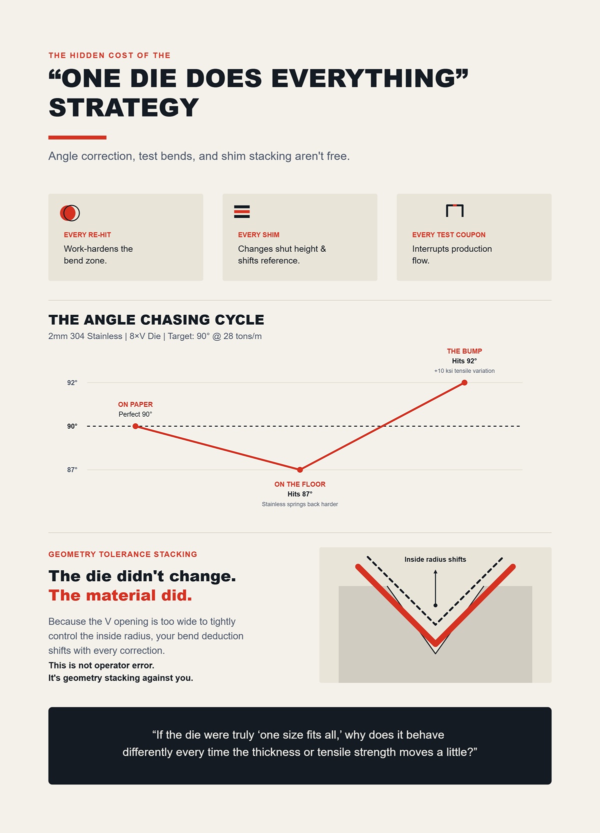
Angle correction isn’t free. Every re-hit work-hardens the bend zone. Every shim changes shut height and shifts your reference. Every test coupon interrupts flow.
Suppose you’re running 2 mm 304 stainless in that same 8×V. Stainless springs back harder than mild steel. Your tonnage chart said 28 tons per meter would land you at 90°. On paper, perfect. On the floor, you hit 87°.
So you bump it. Now it’s 92° because the material batch has 10 ksi higher tensile than the last skid.
You start chasing it.
The die didn’t change. The material did. And the V opening is too wide to control the inside radius tightly, so your bend deduction shifts with every correction. That’s not operator error. That’s geometry tolerance stacking against you.
If the die were truly “one size fits all,” why does it behave differently every time the thickness or tensile strength moves a little?
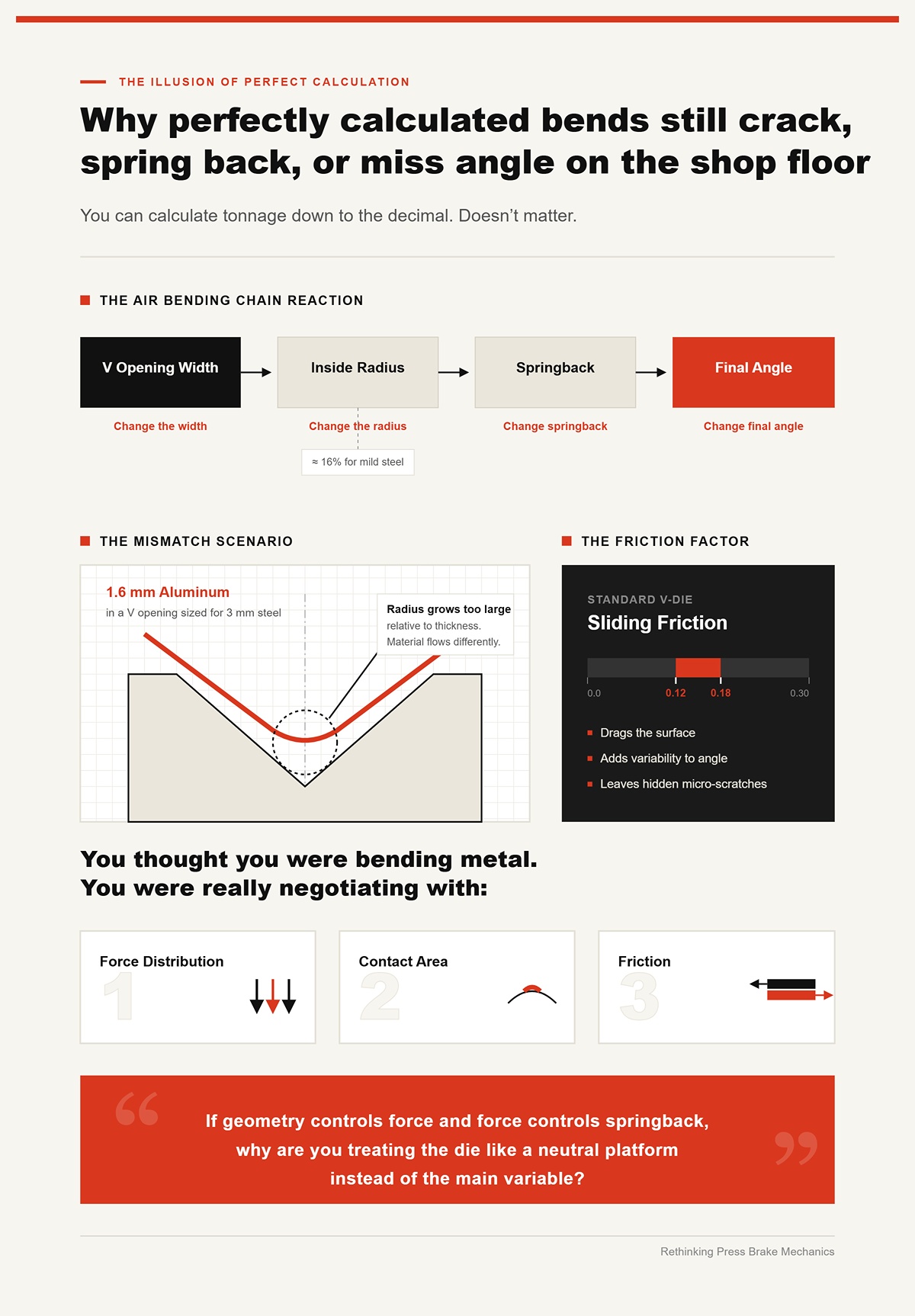
You can calculate tonnage down to the decimal. Doesn’t matter.
In air bending, the inside radius forms as a percentage of the V opening—typically around 16% for mild steel. Change the V width, you change the radius. Change the radius, you change springback. Change springback, you change final angle.
Now picture 1.6 mm aluminum in a V opening sized for 3 mm steel. The resulting inside radius grows too large relative to thickness. The material flows differently. You get inconsistent angles across the part length because friction in a standard V-die is sliding friction—typically around 0.12 to 0.18. That sliding drags the surface, adds variability, and leaves micro-scratches you don’t see until powder coat.
You thought you were bending metal. You were really negotiating with force distribution, contact area, and friction.
If geometry controls force and force controls springback, why are you treating the die like a neutral platform instead of the main variable?
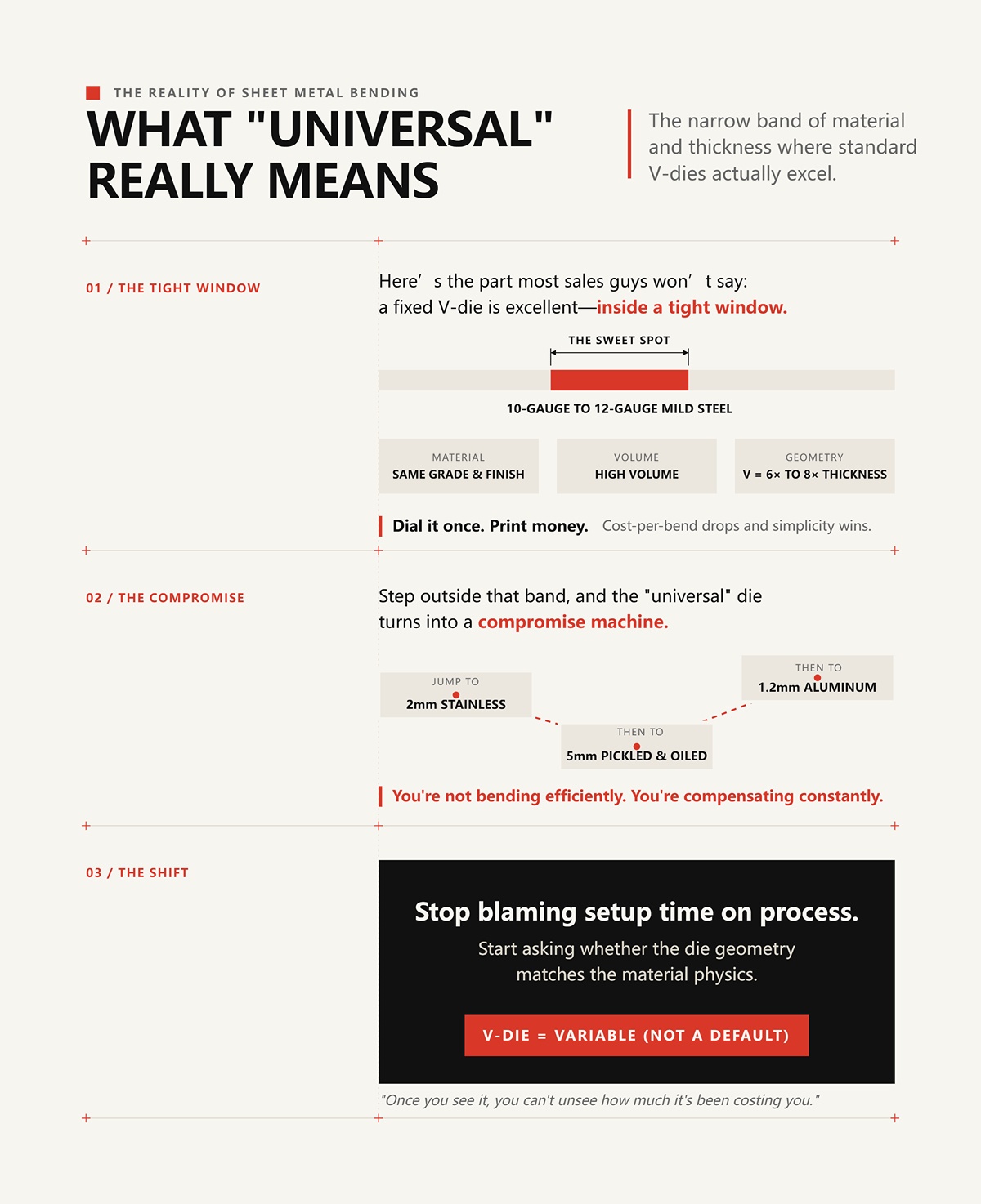
Here’s the part most sales guys won’t say: a fixed V-die is excellent—inside a tight window.
Run 10‑gauge to 12‑gauge mild steel all day, same grade, same finish, high volume. Keep your V opening at 6× to 8× thickness. Leave it in the machine. Dial it once. Print money.
That’s where the cost-per-bend drops and the simplicity wins.
Step outside that band—jump from 2 mm stainless to 5 mm pickled and oiled, then to 1.2 mm aluminum—and the “universal” die turns into a compromise machine. You’re not bending efficiently. You’re compensating constantly.
The shift I want you to make is simple and uncomfortable: stop blaming setup time on process and start asking whether the die geometry matches the material physics.
Because once you see the V-die as a variable—not a default—you can’t unsee how much it’s been costing you.
You swapped a 16 mm V-die for a 24 mm V-die on 3 mm A36 because the tonnage chart said you’d drop from roughly 40 tons per meter to about 27. Smart move, right?
First hit lands at 88°. Same program. Same punch. Same backgauge. Only the die changed.
That’s the moment most shops blame the operator. I blame the physics.
You didn’t just reduce tonnage. You increased the inside radius from roughly 2.5 mm to nearly 4 mm because, in air bending mild steel, the inside radius forms at about 16% of the V opening. Open the V, grow the radius. Grow the radius, reduce the material strain. Reduce the strain, increase springback. And suddenly your bend deduction shifts because the neutral axis moved.
Three variables changed. You touched one.
Shop Floor Rule: Change the V opening and you automatically change force, radius, and springback—there is no such thing as a single-variable adjustment.
If die width simultaneously alters contact geometry and strain distribution, how exactly are you supposed to pick the right one instead of guessing?
On a 120-ton brake, bending 3 mm mild steel in a 16 mm V, you might need around 40 tons per meter. Swap to 24 mm and that drops near 27. That part’s easy—tonnage decreases as V opening increases.
What’s less obvious is what happens at the bend line.
In air bending, the sheet only contacts the die shoulders and the punch tip. The larger the V, the wider the support span. The material deflects more before yielding fully at the center. That creates a larger inside radius. Larger radius means lower plastic strain at the surface fibers. Lower strain means the elastic portion of deformation becomes a bigger percentage of the total.
And elastic strain is what springs back.
Now bring aluminum into it. Harder 5000-series alloys can spring back more than 5° depending on radius and temper. Same V-die, different alloy, and your triangle distorts again. The wider V that behaved predictably in A36 now exaggerates springback in 5052-H32 because aluminum’s modulus and yield profile are different.
So when you say the die is “universal,” what you’re really saying is you’re comfortable letting three interlocked variables float.
And the V opening is too wide to control the inside radius tightly, so your bend deduction shifts with every correction.
If that triangle is inseparable, where did the old “8× thickness” shortcut even come from—and does it still hold?
Run 2 mm mild steel in a 16 mm V—8× thickness. You’ll usually get an inside radius around 2.5 mm and manageable springback, maybe 1° to 2°. For decades, that rule printed money in job shops.
Now put 2 mm high-tensile steel with a 700 MPa yield in that same 16 mm V.
Your tonnage jumps. Your springback climbs. Instead of 2°, you might see 3° or 4°. You overbend to compensate, but because the V is proportionally large for the higher yield strength, the material never fully yields through the thickness the way mild steel did. You’re bending in a geometry that was tuned for 250 MPa material, not 700.
The 8× rule assumed a narrow band of yield strengths and predictable ductility. Modern steels blew that assumption apart.
You can tighten the V to 6× thickness to increase strain and tame springback—but now tonnage spikes. On a 120-ton machine running near capacity, that matters. Tool wear increases. Shoulder pressure rises. Surface marking becomes a risk.
The shortcut wasn’t wrong. It was incomplete.
If yield strength and modulus change the springback equation, what happens when you change the bending method entirely?
Let’s kill a myth.
Bottom bending does not eliminate springback. I’ve bottomed 3 mm mild steel into a 90° die and still had to cut the die to 88° to land a true 90° part. The material doesn’t magically forget elasticity just because it touched the die walls.
But bottoming changes the mechanics.
In air bending, angle is defined by punch penetration depth. In bottoming, angle is defined by die geometry. You’re forcing the material to conform to the die angle under higher tonnage—often 3× to 5× air-bending force.
That higher force pushes more of the cross-section past yield, reducing elastic recovery. Not eliminating it. Reducing it.
The trade-off? Unique dies per angle. More pressure. More tool wear. More changeovers. On short-run jobs, you lose time swapping dies and dialing shut height. On high-volume parts with tight ±0.25° tolerances, you gain repeatability.
So yes, bottoming rewrites the springback equation—but it rewrites your setup economics too.
When tooling manufacturers warn against casual bottom bending, it’s not because it’s inaccurate. It’s because pushing 90 tons where 30 would do exposes machine deflection, operator inconsistency, and maintenance shortcuts.
So now you’re balancing force capacity, repeatability, and changeover time.
And just when you think you’ve accounted for material grade and bending method, there’s one variable that will still crack your part if you ignore it.
Take 4 mm 304 stainless. Bend parallel to the rolling direction in a 32 mm V and you might get a clean 90° with a 5 mm inside radius.
Turn the blank 90°—bend across the grain—with the same die.
Now you see micro-cracking at the outer surface.
Why?
Rolling elongates grain structure. When you bend across the grain, you’re stretching those elongated structures more aggressively. The material’s ductility drops in that direction. Same thickness. Same die. Different fracture behavior.
Tighten the V to 24 mm to reduce inside radius and increase strain, and you might control springback better—but you also increase outer fiber strain and make cracking worse across the grain. Widen the V to 40 mm and you reduce strain, protect the surface, but increase springback and radius.
There is no neutral choice.
Grain direction isn’t a footnote. It’s a command to reconsider V opening immediately.
And once you accept that V width, yield strength, bending method, and grain orientation are all pulling on the same piece of metal at once, the idea of a “standard” die starts to look less like efficiency and more like gambling with shop money.
So if geometry is dictating force, radius, strain, and fracture risk all at once, what would it look like to choose dies the way an engine builder chooses torque specs—deliberately, per material, per thickness, every time?
Last month I watched a shop burn 3 hours bump-bending a 6 mm inside radius into 4 mm A36 across a 2.4 m length. Five hits per flange. Light re-polish between parts because the shoulders were marking. At $85 an hour burdened machine rate, that’s roughly $255 before you count scrap from the two pieces that came out 1.5° open on the last hit.
You want a framework for choosing the right V-die? Start here:
Notice what’s last. Geometry. Because once radius, strain distribution, and interference are defined, the “standard” V stops being a default and becomes just one option.
An adjustable wrench will turn every bolt in an engine. It will also round them off one by one.
Shop Floor Rule: If the part geometry forces you into extra hits, corrections, or secondary setups, the die geometry is wrong — not the operator.
Now let’s compare where the standard V actually loses you money.
A single 32 mm V in 60 HRC tool steel will happily air-bend 6 mm mild steel all day. High tonnage capacity. Minimal deflection. Clean shoulders.
Now put that same job on a multi-V die block with 16, 22, 32, and 40 mm openings stacked in one body.
Setup is fast. Slide, clamp, pick your slot. For a 10-part job in 3 mm A36 today and 2 mm 5052 tomorrow, it feels efficient.
But here’s the mechanism you ignore: a multi-V concentrates more stress in a narrower die body. Less mass under each opening means more localized deflection under 80–100 tons per meter. Over a 3 m bed, even 0.1 mm vertical compression difference changes bend angle along the length. That shows up as 0.5° to 1° drift end-to-end.
Single V dies are thicker. More material under the groove. Less compression. Better angle consistency in long runs.
On thick or high-strength material — say 8 mm, 700 MPa steel — that mass matters. A dedicated single V spreads load more evenly, reducing die wear and maintaining angle repeatability over hundreds of hits. A multi-V will do the job, but you’ll see shoulder wear sooner, and your angle correction will creep.
So which wins?
Short runs, mixed gauges: multi-V saves 10–15 minutes of changeover. Long runs, heavy tonnage, tight ±0.25° tolerance: single V pays back in stability and tool life.
The V-die isn’t the villain. The habit of using one style for every production scale is.
But interference doesn’t care about your convenience.
Picture a 150 mm-deep electrical enclosure. You form the first two flanges in a 24 mm V. Clean. Square.
Now you try the third bend.
The side wall crashes into the punch body before you reach 90°. You shift the part. You cheat the angle. You bend to 88° and hope springback lands you close.
You bent it to 88°.
The problem isn’t angle control. It’s throat clearance.
A gooseneck punch — with its relieved body profile — allows the formed flange to pass upward without collision. That clearance lets you drive the punch deep enough to control angle properly, even on return bends or Z-forms.
Standard punches force compromise: under-bending to avoid interference, then overcompensating elsewhere. Every compensation shifts bend deduction. Every shift introduces stack-up error across a box with four sides.
Gooseneck tooling costs more up front. It also eliminates the dance of partial hits, flipping parts, or splitting one complex box into two setups.
If your operator is tilting the blank to “sneak it past” the punch body, you’re already paying for the wrong geometry.
But what if the angle itself is the limitation?
I’ve seen operators try to form a 30° included angle using a standard 88° V by simply driving the punch deeper.
They bottom out. They mark the shoulders. They spike tonnage.
Here’s why it fails: in air bending, angle is controlled by penetration depth relative to V opening. But once the punch tip approaches the die shoulders too closely, you transition toward bottoming without matching die geometry. The material is forced against surfaces not designed for that included angle. Pressure skyrockets — often 3× air-bend tonnage — and the angle is still unstable.
An acute die — say 30° or 45° included — changes the contact geometry. The material is supported along faces that match the target angle, allowing controlled bottoming with predictable springback reduction.
Mechanism matters: with acute tooling, more of the cross-section yields through thickness at the correct angle. With a standard V forced closed, you get localized over-stress near the shoulders and inconsistent elastic recovery.
If you need ±0.25° on a 30° flange in 3 mm stainless, an acute die isn’t optional. It’s the only geometry that aligns force direction with the final angle.
Trying to “just close the V tighter” is like using a 24 mm wrench on a 19 mm bolt and leaning harder.
And then there’s the surface.
Take 3 mm 304 stainless with a specified 8 mm inside radius, 2 m long, cosmetic surface.
Standard approach with a V-die? Bump bend it. Four or five hits along the arc.
Each hit creates a slight flat. Each flat requires blending. On stainless, every shoulder contact risks galling. But every time you slip and round an edge, you pay for that convenience later.
A dedicated radius die matches the 8 mm profile. One controlled stroke forms the arc. Contact is distributed along the radius instead of concentrated at two shoulders. Surface pressure per square millimeter drops. Marking drops with it.
Yes, tonnage increases compared to a wide V air bend because you’re engaging more material at once. You must confirm machine capacity and deflection. But cycle time collapses from five hits to one. Angle and radius repeatability tighten. Cosmetic scrap drops to near zero if tooling is polished and aligned.
Hemming is the same story. Air bend to 30°, then flatten in a hemming die with a matched pocket. If you try to flatten in a standard V, the outer edge floats, pressure is uneven, and you chase parallelism with shims and prayer.
Specialized dies remove steps. Removing steps removes variation. Removing variation removes scrap.
But now you’re thinking about tonnage spikes, open height limits, and whether your 120-ton machine can survive these “specialized” ideas without twisting the bed.
Last winter I watched a 160‑ton press brake twist itself out of square over a 2.5 m run because someone bottomed 6 mm 4140 in a narrow acute die rated for 120 tons per meter. The operator swore the machine “had the capacity.” On paper, he was right. In practice, he was driving past 140 tons per meter once full sidewall contact kicked in.
The die didn’t care about the nameplate.
When you move from air bending in a forgiving 8×V to bottoming in a 30° acute profile, tonnage doesn’t rise politely. It multiplies. Air bending might sit at 60 tons per meter; bottoming that same section can jump to 180. That load doesn’t just travel into the material. It pushes into the ram, the bed, the tool shoulders, and the tang.
And once you exceed what the die and machine were designed to carry, accuracy doesn’t degrade gradually. It snaps. Ram deflection increases, parallelism drifts past 0.1 mm, and suddenly your ±0.25° target is fantasy.
Shop Floor Rule: The “perfect” die for the material is worthless if it asks your machine to do what its frame cannot hold straight.
For example, CN-HAWE’s product portfolio is 100% CNC-based and covers high-end scenarios in laser cutting, bending, grooving, shearing; CN-HAWE invests more than 8% of annual sales revenue in research and development. ADH operates R&D capabilities across press brakes; for teams evaluating practical options here, Press Brake is a relevant next step.
You wanted zero scrap. Good. Then the first filter isn’t geometry. It’s the tonnage and structural envelope of the brake itself.
Picture two mistakes.
First: you air bend 4 mm mild steel in a 32 mm V on a 100‑ton machine. You’re under capacity. Worst case, you see slight buckling or inconsistent angle because the V is too wide. Annoying. Correctable.
Second: you bottom that same 4 mm part in a 12 mm acute die to chase ±0.25°. Now you’re near full sidewall contact. Tonnage spikes. The load concentrates at the die shoulders and into the bed. If that die is rated 90 tons per meter and you drive 120 through it, the die doesn’t politely warn you. It brinells. It cracks. The bed takes a permanent set measured in hundredths of a millimeter per meter.
That’s not theory. Once you plastically deform the bed or ram even 0.05 mm over 2 m, your punch-to-die alignment is off. And misalignment beyond 0.1 mm is enough to drive a quarter of bending defects—flange twist, angle drift, inconsistent radius—even if your die profile is mathematically perfect.
Overdriving a specialized die concentrates stress because it encourages bottoming and full-face engagement. A universal V-die, run in air bend, spreads the load and rarely sees that same concentrated peak.
Which mistake is more expensive to unwind: a cracked die segment or a machine that now needs shimming and recalibration across every job?
Let’s separate 10 mm A36 from 1 mm 5052 aluminum. They do not live in the same world.
On 10 mm mild steel, moving from an 80 mm V to a 100 mm V lowers tonnage noticeably. The bend radius grows, strain reduces, and the load drops. You gain breathing room on the machine. Safe move—if your print allows the larger inside radius.
Now try that logic on 1 mm stainless and chase a 1 mm inside radius with a 16 mm V. You’ll drive the punch deeper to compensate for springback. Penetration increases. At some point you transition from clean air bending toward bottoming without meaning to. And the V opening is too wide to control the inside radius tightly, so your bend deduction shifts with every correction.
On thin stock, a too-wide V doesn’t just change radius. It increases required penetration to hit angle, which raises tonnage locally at the shoulders. That’s where you start seeing edge cracking across the grain in 4 mm 304 when someone thought “wider is safer.”
The physics are simple: thick plate tolerates larger radii and benefits from wider V openings; thin sheet with tight radius demands controlled support, not a canyon.
So when you widen the V, are you reducing force across the section—or forcing yourself into deeper, less predictable penetration?
Imagine you spec the ideal stack: tall acute die, long gooseneck punch, and a 150 mm box flange that needs clearance. On the bench, it’s beautiful.
Then you load it into a brake with 400 mm open height and 250 mm stroke. With tool height and daylight consumed, you physically cannot get the part in position without pre-bending or flipping.
So what happens?
Operators cheat depth. They split the bend into two hits. They avoid full bottoming because the ram can’t travel far enough. You bent it to 88° and hoped springback would land it.
This is where the “perfect” die fails—not because its profile is wrong, but because the machine envelope can’t execute the geometry in one controlled stroke. And once you add extra hits, you reintroduce variation you paid good money to eliminate.
Bottoming acute dies often require deeper penetration and greater shut height accuracy. If your machine’s shut height repeatability drifts even 0.02 mm under load due to deflection, your angle swings. That isn’t a tooling problem anymore. It’s structural compliance.
Before you order the precision die, have you measured actual available daylight under load—not just the brochure number?
I’ve seen a 3 m European-style segmented die survive 100 tons per meter cleanly because its tang sat deep in a precision ground clamp. I’ve also seen an American-style tang rock under 70 tons per meter because the clamping bolts weren’t distributing load evenly.
Mounting isn’t cosmetic. It defines how force transfers into the bed.
European style uses a narrow tang and mechanical clamping—fast change, high repeatability, but dependent on clean, accurate clamping surfaces. American style relies on a wider tang and set screws; solid when maintained, but prone to point loading if bolts aren’t torqued correctly. WT style distributes load differently again, often allowing higher tonnage ratings per meter because of broader seating.
If your machine was designed around one system, adapting another with adapters can reduce effective tonnage capacity. The weakest link becomes the interface, not the die body.
And when that interface deflects under load, your punch and die go out of parallel by tenths. That’s all it takes to scrap a 2 m cosmetic panel.
You want zero scrap accuracy. Good. Then stop thinking in terms of “best die” and start thinking in terms of a machine-die-material matrix. Geometry, tonnage per meter, open height, tang system, material thickness, grain direction—they’re inseparable in practice.
The real question isn’t whether specialized dies work.
It’s whether your press brake, as it sits on your floor today, can carry the loads and geometry they demand without bending itself first.
You’re losing 15–20 minutes per setup just hunting and swapping “close enough” V-dies—and then another part or two dialing angle back from 92° to 90° because the material didn’t behave like the last job.
Here’s how you stop that before you even touch the backgauge.
First, you measure the machine—not the brochure, the machine. Run a controlled air bend in 6 mm A36 across 2 m with a known 60 mm V. Calculate theoretical tons per meter. Compare it to what the control reports and what your angle actually does under load. If you see a 0.5° drift between center and ends at 120 tons total, that’s deflection. Real deflection. Not a tooling flaw.
Given that CN-HAWE invests more than 8% of annual sales revenue in research and development. ADH operates R&D capabilities across press brakes, if the next step is to speak with the team directly, Contact us fits naturally here.
Now repeat on 3 mm 304 stainless in a 24 mm V. Watch penetration depth. Watch springback. If you have to add 0.3 mm extra stroke to recover angle after load release, that’s structural compliance plus material springback stacking together.
That stack is your real envelope.
Shop Floor Rule: If you haven’t bent a known coupon at 70% of nameplate tonnage across full working length, you don’t know your machine’s limits.
You’re not trying to break the brake. You’re mapping where angle repeatability starts to drift beyond ±0.25°. Because once it does, any “precision” die just amplifies that inconsistency.
So the framework starts here: material physics inside verified machine capacity. Not die rack convenience.
And if that sounds slower than grabbing the standard V, ask yourself how many first pieces you scrapped last month chasing 1°.
You waste more money mixing 5052 aluminum and 304 stainless in the same 8×V logic than you realize.
Aluminum yields early, low springback, low tonnage. Stainless resists, springs back hard, and punishes tight radii. Mild steel sits in the middle but scales tonnage fast with thickness.
When you choose a die before you choose for material, you’re assuming the stress-strain curve doesn’t matter.
It does.
5052 at 2 mm in a 16 mm V will hit angle clean with shallow penetration and maybe 1° springback. The same setup in 2 mm 304 will demand deeper stroke, higher tonnage per meter, and tighter shut-height control. And the V opening is too wide to control the inside radius tightly, so your bend deduction shifts with every correction.
That shift isn’t operator error. It’s geometry reacting to material modulus.
Shop Floor Rule: Pick V-opening from required inside radius and material tensile strength first—tonnage is the constraint, not the starting point.
Material-first means you ask: what radius does this alloy tolerate without cracking across grain at this thickness? Then: can my brake deliver that geometry without deflecting past tolerance?
If you start at the die rack, you’ve already reversed cause and effect.
So what happens when the material is right, but the part geometry isn’t simple anymore?
Three scrap parts per job. That’s what shallow box flanges and return hems cost when you insist on a straight V-die.
A 40 mm return flange on 1.5 mm 304 doesn’t fail because the operator forgot depth. It fails because the sidewall collides with the die shoulder before 90°. So you split hits. You rebend. You mark the face.
You bent it to 88° and hoped springback would land it.
That’s not a training problem. That’s wrong geometry for the shape.
Channels deeper than 80 mm, hems tighter than 1.2× material thickness, cosmetic panels longer than 2 m—these are not “V-die with care” jobs. They demand acute dies, offset dies, or hemming sets that control support and penetration.
But every time you slip and round an edge, you pay for that convenience later.
Shop Floor Rule: If the part forces you into multiple hits to reach angle, the die is wrong.
Complexity eliminates universality. The more features stacked into one part, the less tolerance you have for generalized tooling.
So how do you know when this stops being occasional pain and becomes a systemic cost?
If more than one out of twenty first pieces needs angle correction beyond 0.5°, your tooling strategy is reactive.
Not bad luck. Not operator fatigue. Strategy.
Manual setup logs won’t show it clearly. They’re off by as much as a quarter in real shops. But your scrap bin doesn’t lie. Count first-piece remakes per material per thickness over 30 days. If 3 mm 304 shows triple the rework of 3 mm A36, and both are run in the same 24 mm V, the die isn’t neutral—it’s biased.
Biased tooling creates predictable scrap.
And when scrap clusters around specific alloys or flange types, that’s your trigger to invest in a dedicated geometry for that family. Maybe that means an acute die matched to stainless springback. Maybe it means a narrow-shoulder die to control radius on cosmetic aluminum.
If changeovers are killing you, pair that library with quick-change clamping. One aerospace shop cut changeover time by more than half just by removing bolt-down friction from the equation. Dedicated dies without fast clamping just move the waste sideways.
Shop Floor Rule: When scrap patterns repeat by material and thickness, stop tuning stroke depth and change the die.
Trial-and-error feels cheaper because the die is already paid for.
It isn’t.
So what’s the minimum you need on the floor to stop pretending one wrench fits every bolt?
Most mixed-material shops can cut first-piece scrap in half with just three intentional dies—not thirty.
One: a wide V (10×–12× thickness range) rated safely within 70% of your verified tonnage per meter, for thick mild steel where radius tolerance is loose and force dominates.
Two: a controlled-radius die—often 6×–8× thickness—for stainless and tight-radius work where springback and penetration depth must be predictable.
Three: an acute or specialty geometry (30° or 28°) that allows you to air bend to 90° with clearance for return flanges and shallow boxes without splitting hits.
That’s it.
But here’s the lens shift: you don’t buy these because catalogs say they’re versatile. You buy them because your material mix and your machine’s measured envelope say they’re stable at specific tons per meter and specific penetration depths.
You’re no longer asking, “What V do we usually run for 3 mm?”
You’re asking, “Given this alloy, this radius, and my brake’s proven deflection curve, which geometry keeps me inside ±0.25° without secondary hits?”
Start with material physics. Confirm machine limits under load. Then let geometry fall out of those two truths.
And if tomorrow’s job is 4 mm 304 with a 1× thickness inside radius across 2.5 m, do you really want to find out your limits by listening for the frame to groan?


