

The first ten parts look perfect. The hem is flat, tight, clean enough to photograph for the sales brochure.
Two hundred panels later, you’re holding one up to the light and there it is—a hairline split riding the outer radius like a fault line in dry earth. Same die. Same settings. Same operator. So what changed?
If you think the answer is “the flat top must not be flat enough,” you’re already walking toward the scrap bin.
I’ve watched good operators pat a single-stage hemming die like a loyal dog. “Flat top. Nice and even. We’re good.” That thinking worked when mild steel was king and tensile strength hovered around 340 MPa tensile strength. The material stretched, yielded, forgave you.
Modern automotive outer panels? You’re staring at 980 MPa tensile strength and smiling because the hem looks flat.
A flat top tells you what happened at the surface. It tells you nothing about what happened inside the metal fibers during that one violent, combined pre-bend-and-flatten motion. And that’s where the trouble starts.
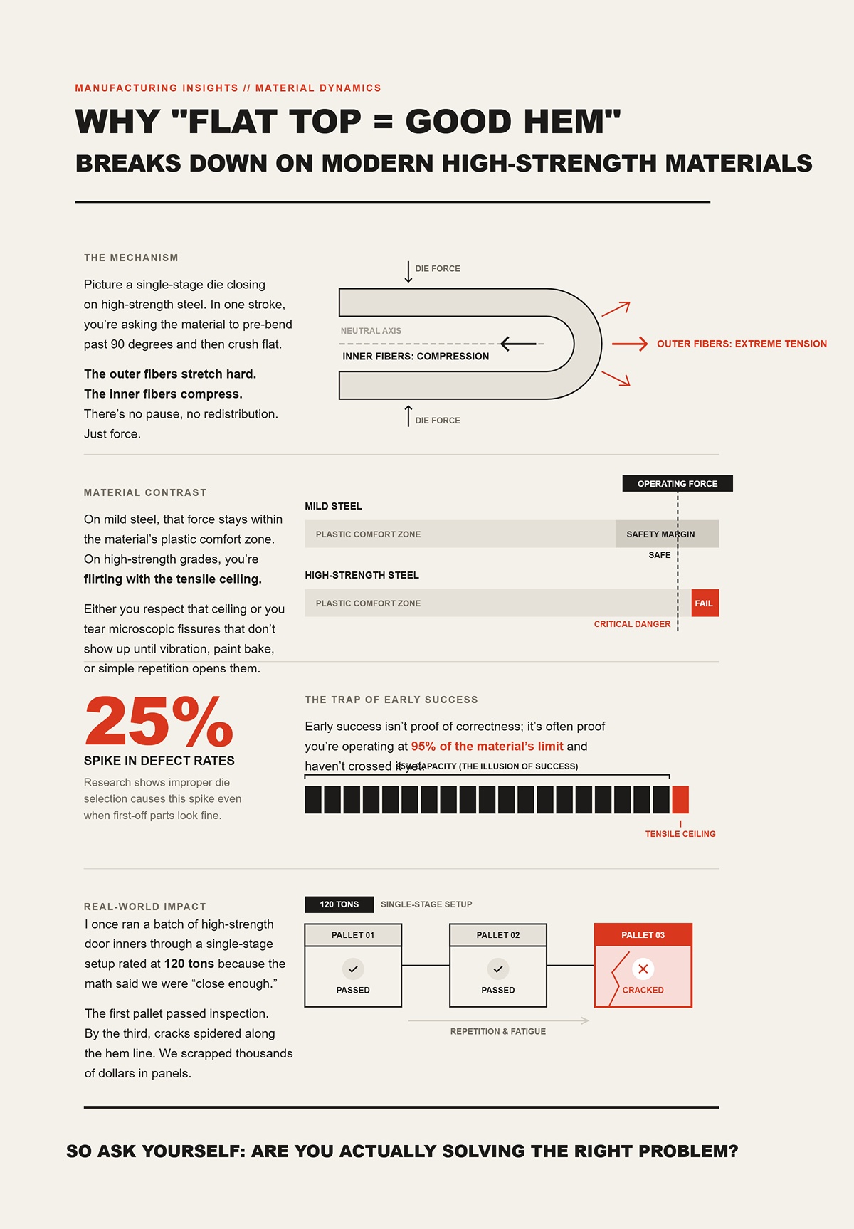
Picture a single-stage die closing on high-strength steel. In one stroke, you’re asking the material to pre-bend past 90 degrees and then crush flat. The outer fibers stretch hard. The inner fibers compress. There’s no pause, no redistribution. Just force.
On mild steel, that force stays within the material’s plastic comfort zone. On high-strength grades, you’re flirting with the tensile ceiling. Either you respect that ceiling or you tear microscopic fissures that don’t show up until vibration, paint bake, or simple repetition opens them.
There’s research showing improper die selection can spike defect rates by 25% even when first-off parts look fine. That’s the trap. Early success isn’t proof of correctness; it’s often proof you’re operating at 95% of the material’s limit and haven’t crossed it yet.
I once ran a batch of high-strength door inners through a single-stage setup rated at 120 tons because the math said we were “close enough.” The first pallet passed inspection. By the third, cracks spidered along the hem line. We scrapped thousands of dollars in panels because I trusted the flat top instead of the tensile boundary. That lesson wasn’t cheap.
So ask yourself: are you actually solving the right problem?
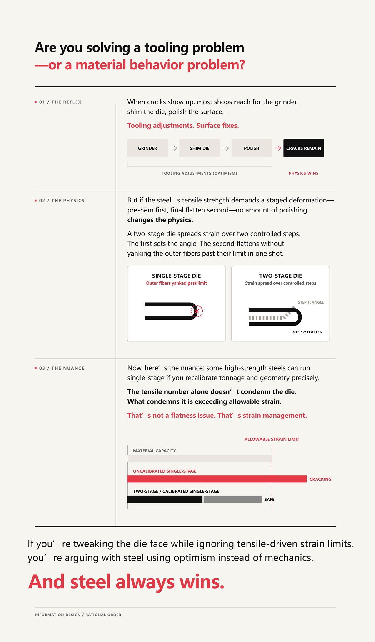
When cracks show up, most shops reach for the grinder, shim the die, polish the surface. Tooling adjustments. Surface fixes.
But if the steel’s tensile strength demands a staged deformation—pre-hem first, final flatten second—no amount of polishing changes the physics. A two-stage die spreads strain over two controlled steps. The first stage sets the angle. The second flattens without yanking the outer fibers past their limit in one shot.
Now, here’s the nuance: some high-strength steels can run single-stage if you recalibrate tonnage and geometry precisely. The tensile number alone doesn’t condemn the die. What condemns it is exceeding the material’s allowable strain during that combined motion.
That’s not a flatness issue. That’s strain management.
If you’re tweaking the die face while ignoring tensile-driven strain limits, you’re arguing with steel using optimism instead of mechanics.
And steel always wins.
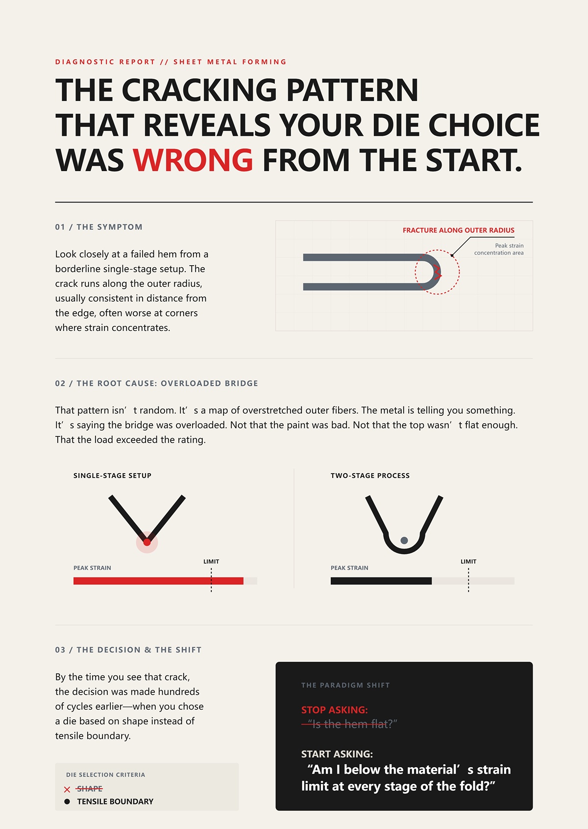
Look closely at a failed hem from a borderline single-stage setup. The crack runs along the outer radius, usually consistent in distance from the edge, often worse at corners where strain concentrates.
That pattern isn’t random. It’s a map of overstretched outer fibers. A two-stage process would have reduced peak strain in that first bend, lowering the stress before flattening ever happened.
The metal is telling you something. It’s saying the bridge was overloaded. Not that the paint was bad. Not that the top wasn’t flat enough. That the load exceeded the rating.
By the time you see that crack, the decision was made hundreds of cycles earlier—when you chose a die based on shape instead of tensile boundary.
So the shift you need is simple and brutal: stop asking, “Is the hem flat?” and start asking, “Am I below the material’s strain limit at every stage of the fold?”
You want to know how to verify you’re below the material’s strain limit at each stage?
Start with the bend radius and the tensile number. If you’re hemming 1.2 mm steel at 980 MPa tensile strength, and your effective inside radius during pre-bend drops below roughly 1× thickness, you’re already pushing outer-fiber strain toward 15–20%. That’s not a guess; outer strain in bending is approximately thickness divided by twice the inside radius. Halve the radius, double the strain. Steel doesn’t care how confident you feel about it.
Now picture doing that pre-bend and the final crush in one uninterrupted stroke.
In a single-stage die, the material is forced past 90 degrees and flattened while it’s still elastically loaded from the initial bend. You don’t get a pause. You don’t get redistribution. You get accumulated strain. And when that accumulated strain exceeds what 980 MPa tensile strength can plastically accommodate, micro-fractures start forming long before your calipers tell you anything is wrong.
So the real comparison isn’t speed. It’s whether the architecture lets the metal relax between insults—or compounds them.
Run a single-stage hem slowly and watch the side profile. As the punch descends, the sheet first begins to rotate around the die edge. The neutral axis—the layer inside the thickness that experiences zero strain—shifts toward the inside radius as tension builds on the outside fibers.
Then the die keeps traveling.
Before the neutral axis can stabilize in a clean 30–45 degree pre-hem position, the flat-top geometry forces the leg to collapse. Now the material is no longer just bending; it’s being crushed and re-bent in the opposite curvature as it lays down. The neutral axis migrates again, abruptly, because the strain state changes from pure bending to bending-plus-compression.
You are asking the outer fibers to stretch to form the bend and then accommodate additional displacement as the leg is flattened—without unloading the tensile stress from the first event. In a single stroke, you are asking the outer fibers to stretch and collapse at the same time—and high-strength steel does not forgive that demand.
If you section a cracked hem from this setup, the fracture line tracks the outer radius from the original bend, not the final flat. That tells you the failure initiated during peak tensile strain, not during cosmetic flattening.
So what changes if you stop forcing both events into the same mechanical moment?
A proper two-stage die forms an acute angle first—typically 30 to 45 degrees—with a defined V-opening. That V-opening matters. A wider V increases the lever arm, reducing required tonnage and spreading the bend over a larger radius. Narrow the V and required tonnage spikes fast. Concentrate force enough and even mild steel complains.
In stage one, you control the inside radius. You calculate outer-fiber strain. You check it against the material’s elongation at fracture. If your 1.2 mm, 980 MPa tensile strength steel can safely take, say, 12% true strain before necking, you design that first bend to stay comfortably below it—maybe 8–9%. Conservative. Boring. Profitable.
Then you release the ram.
That release is not a formality. It allows elastic energy to dissipate. The neutral axis stabilizes in its new position. Residual stresses redistribute through the thickness instead of stacking.
Stage two is not another aggressive bend. It’s controlled compression between flat surfaces. The outer fibers are no longer being asked to stretch to create curvature; they’re being guided into contact. Different strain mode. Lower tensile demand.
Two-stage architecture is elastic energy management. Not operator preference. Not tradition. Management.
Which brings up a practical headache you’ll meet the first time you run high-strength panels all day.
During that first acute strike, material doesn’t just bend downward. It wants to move sideways. That lateral thrust increases with tensile strength and thickness because the stored elastic energy is higher. With 980 MPa tensile strength, that side force is not polite.
A basic sliding two-stage die relies on mechanical clearance. If your alignment is off or your lubrication inconsistent, lateral thrust can cock the upper section and gall the surfaces. You’ll feel it as inconsistent hem thickness from left to right.
A spring-loaded two-section die handles the transition differently. The upper section forms the pre-hem in its V. As tonnage increases, springs compress and allow the upper assembly to transition into the flattening state while maintaining guided alignment. The die itself absorbs part of that lateral impulse instead of transmitting it into the frame or binding at the shoulders.
That matters because jamming isn’t just a nuisance. Binding changes local pressure distribution. Change the pressure distribution and you change local strain. Change local strain and you either respect the tensile limit or scrap the batch.
This is the boundary line: if your architecture can’t control radius in stage one, release elastic energy before stage two, and manage lateral thrust without spiking local pressure, single-stage is gambling with high-strength steel. Two-stage is engineering around it.
So the next question isn’t “Which die is faster?”
It’s this: under your specific thickness and tensile strength number, can you prove—mathematically and mechanically—that peak outer-fiber strain in each stage stays below the material’s limit, or are you trusting that the first ten parts look perfect?
You want to know how to calculate peak outer-fiber strain before you cut steel, not after you crack it.
Start with the one number that doesn’t lie: outer-fiber true strain in bending ≈ thickness ÷ (2 × inside radius).
If you’re hemming 1.2 mm sheet over a 0.6 mm inside radius in a single hit, that’s 1.2 ÷ (2 × 0.6) = 1.0. One hundred percent engineering strain at the surface. Convert to true strain and you’re still flirting with numbers no high-strength automotive sheet will tolerate. Mild steel with 45,000 PSI tensile strength might neck gracefully and survive because it has generous elongation. Push the same geometry into 80,000 PSI tensile strength and above, and elongation collapses. The math doesn’t care how fast your press cycles.
Then layer in what a single-stage die actually does: it doesn’t just form that radius. It immediately crushes and re-bends the leg flat, tightening the effective radius mid-stroke. Your clean 0.6 mm design radius becomes 0.4 mm under load. Re-run the math: 1.2 ÷ (2 × 0.4) = 1.5. That spike happens before the material can unload. That’s not efficiency. That’s a strain multiplier.
So where does single-stage actually make sense?
Picture 0.8 mm low-carbon steel, tensile around 40,000–50,000 PSI, hemmed over a die with a true inside radius near material thickness. Run the same equation: 0.8 ÷ (2 × 0.8) = 0.5. Fifty percent engineering strain at the outer fiber sounds high until you remember low-carbon sheet may carry 30% elongation in a tensile test and redistribute strain through thickness during bending. Add a generous V-opening—6× thickness—and you’re not forcing a knife-edge radius. You’re guiding it.
In that window—thin gauge, soft steel, wide opening—the single stroke stays within allowable strain. The outer fibers stretch, yes, but they’re not being yanked past their ductility ceiling while simultaneously crushed flat. The geometry is forgiving, the material is forgiving, and the architecture doesn’t stack insults beyond what the sheet can absorb.
That’s when single-stage shines. Short cycle. Fewer components. Less to maintain.
But you only get to enjoy that simplicity if the material gives you margin.
What happens when it doesn’t?
Take 1.4 mm dual-phase steel rated at 80,000 PSI tensile strength. Typical total elongation might sit near 12–14%. That’s your real ceiling, not the tensile number stamped on the cert.
Design a hem with an effective inside radius of 0.7 mm. On paper, 1.4 ÷ (2 × 0.7) = 1.0 engineering strain at the surface before flattening. Even if you argue neutral axis shift reduces that somewhat, you’re nowhere near 12%. You are multiple times beyond it during peak curvature in a single-stage hit. The only reason it doesn’t split immediately is because the strain localizes and redistributes—until it doesn’t.
Now tighten the die to control cosmetic gap and the working radius drops under load. The strain spikes again. This is where the bridge analogy stops being cute. You either stay under the load rating or you crack concrete. There is no motivational speech that changes that.
From the field: once you cross 80,000 PSI tensile strength at automotive hem thicknesses above roughly 1.2 mm, a true single-stage architecture must either (a) open the die dramatically to increase radius—driving tonnage and wear through the roof—or (b) accept outer-fiber strain that exceeds material elongation. Option A erodes tooling and press capacity. Option B erodes parts. Either respect the tensile limit or scrap the batch.
There’s research showing improper die selection can spike defect rates by 25% even when first-off parts look fine. In high-strength hems, that spike isn’t cosmetic drift. It’s latent cracking initiated at peak strain during that compounded motion.
I learned that the hard way. I once ran a high-strength batch on a single-stage setup because the first ten parts look perfect. By part fifty, micro-cracks started telegraphing through paint after e-coat. We scrapped an entire shift’s output and resurfaced a die that wasn’t the real villain. The villain was me ignoring 80,000 PSI tensile strength like it was mild steel.
So how do you know you’ve crossed that invisible line before you see cracks?
Section a suspect hem and polish the cross-section. If the fracture path hugs the original outer bend radius—not the final flat—you exceeded allowable strain during the first curvature event. What condemns it is exceeding the material’s allowable strain during that combined motion, not some cosmetic flattening issue at the end.
Watch springback numbers, too. High springback after a single-stage hem on high-tensile sheet tells you elastic energy is stacked, not released. The more energy trapped, the higher the peak stress was during forming. That’s a clue, not an annoyance.
Then there’s edge consistency. On high-strength material forced through a single-stage die, you’ll see variability left to right as tiny differences in lubrication or alignment create local pressure spikes. Those spikes translate directly into local strain excursions beyond elongation limits. Two-stage spreads that risk across events. Single-stage concentrates it into one moment of truth.
You can calculate strain. You can measure radius under load. You can compare that to documented elongation for your specific heat of steel. Or you can trust cycle time and hope.
And if you’re above 80,000 PSI tensile strength, hope is not a process.
You’ve run the numbers. You’ve seen what happens when 1.2–1.4 mm sheet climbs past 80,000 PSI tensile strength and the outer fiber strain blows through the elongation ceiling in a single hit. So how do you redesign the process?
You stop asking one stroke to do two jobs.
A two-stage hem die splits the operation into a controlled pre-bend—typically 30° to 45°—followed by a separate flattening stroke. That sounds almost polite compared to the violence of a single-stage crush. But the mechanics are different in a way that matters.
Given that CN-HAWE’s product portfolio is 100% CNC-based and covers high-end scenarios in laser cutting, bending, grooving, shearing, for teams evaluating practical options here, Press Brake is a relevant next step.
In the first stage, you form the radius and stop. You let the material yield, shift its neutral axis, and partially unload. Elastic energy dissipates before the second hit ever starts. In the second stage, you’re not creating peak curvature from flat; you’re closing an already yielded leg. Peak strain isn’t stacked in the same instant.
That separation is the difference between flirting with elongation limits and exceeding them.
And once you cross 100,000 PSI tensile strength, there is no middle ground—either you separate the pre-bend from the flattening stroke, or you accept micro-fractures as a production feature.
Picture a 1.6 mm advanced high-strength steel at 100,000 PSI tensile strength. Total elongation might be 10%. You pre-bend it in a dedicated station over a radius equal to material thickness—call it 1.6 mm. Your surface strain approximation is t/(2R): 1.6 ÷ (2 × 1.6) = 0.5. Fifty percent engineering strain at the outer fiber during peak curvature sounds catastrophic until you remember that in pure bending, strain redistributes through thickness and localizes at the surface briefly, then partially relaxes as the part unloads.
Now compare that to a single-stage die that forms and crushes in one motion, effectively tightening the radius under load to, say, 1.0 mm. Run it again: 1.6 ÷ (2 × 1.0) = 0.8. You’ve just spiked peak surface strain by 60%—and you haven’t even accounted for the compressive-through-thickness stresses from flattening. What condemns it is exceeding the material’s allowable strain during that combined motion.
A solid single-stage block can’t pause between those insults. It multiplies them.
In two-stage architecture, the second stroke works on a leg that has already yielded and shifted its neutral axis toward the inside of the bend. The strain required to close from 45° to flat is primarily rotational and compressive at the inner surface, not a fresh tensile peak at the original outer radius. You’re managing where strain goes instead of letting it spike wherever the die geometry dictates.
That’s strain distribution control. Not elegance. Control.
And if strain control is the real objective, does slowing the cycle automatically make you safer?
I’ve seen shops brag about shaving 0.8 seconds off a hem cycle by collapsing two stations into one. On 0.9 mm mild steel at 45,000 PSI tensile strength, fine. The material has 30% elongation to burn and the die opening can sit at 6–8× thickness without drama.
Now try that trick on 1.4 mm dual-phase at 80,000 PSI tensile strength.
Yes, a two-stage die often adds 30–40% to the hemming portion of cycle time. But “slower” isn’t the safety mechanism. The safety comes from reducing peak simultaneous tensile and compressive strain in a single event. You could run a two-stage die fast and still win—because the architecture, not the stopwatch, is what limits strain stacking.
There are edge cases. Widening a single-stage die opening to 10–12× thickness can reduce curvature severity and curb springback in some high-strength steels. That buys you margin. Sometimes enough.
But you pay in tonnage and die fatigue. Running a die at 95–100% of rated capacity doesn’t explode it on day one; it just accelerates wear. Now your “fast” setup is chewing tooling while still flirting with outer-fiber strain limits. Either respect the tensile limit or scrap the batch.
Custom hybrid designs—rolling rods, polyurethane inserts—can soften contact and prevent surface marking on specialty parts. I’ve specified them myself. They help with cosmetics and pressure distribution. They do not repeal the stress–strain curve. Once you’re in six-figure tensile territory, separation of strain events stops being optional and starts being structural.
So what does that look like in production numbers?
Take a hypothetical but realistic scenario: 1.5 mm martensitic steel at 110,000 PSI tensile strength, automotive outer panel hem. Single-stage tool. First article passes visual. The first ten parts look perfect. By part 200, micro-cracks appear along the original outer radius under dye penetrant. After paint, they telegraph. Scrap climbs to 12%.
Switch to a two-stage die. Hem cycle increases 35%. Output per hour drops. Scrap falls to 2% because peak strain no longer exceeds material elongation during a single compounded event.
Run the math over a 10,000-part batch. Even without assigning exact dollars, you know which column hurts more: 35% more hemming time, or 10% additional scrap in high-strength steel plus downstream rework and paint losses.
There’s research showing improper die selection can spike defect rates by 25% even when first-off parts look fine. In high-yield hems, that spike is almost always a strain-management failure, not an operator issue.
So yes, two-stage costs time. It may require more maintenance points. It may demand tighter alignment between stations. But once tensile strength pushes past 100,000 PSI, it isn’t an upgrade for efficiency. It’s a structural requirement, like posting a lower weight limit on a bridge that’s already cracking.
If you’re evaluating whether your current hemming setup can survive sustained runs above 100,000 PSI, this is the point to involve your equipment partner—not after scrap rates climb. CN-HAWE’s 100% CNC-based portfolio spans advanced bending systems and sheet metal automation, backed by dedicated R&D and in-house testing capabilities to validate high-strain applications before they hit your floor. For a technical discussion about die architecture, machine compatibility, or a quotation for a two-stage upgrade, you can contact CN-HAWE to review your material specs and production targets in detail.
And even with the right architecture in place, you can still wreck the batch if you ignore grain direction, lubrication, and die wear—because controlling strain in theory doesn’t mean you’ve controlled it on the floor.
You installed the two-stage die. You checked the shut height. Material cert says 110,000 PSI tensile strength. Architecture is correct.
Parts still crack.
That’s the moment young engineers start blaming heat lots and tool steel grades, because it’s easier than admitting this: once you cross six-figure tensile strength, the die choice stops being the whole story. The structure may be rated for the load, but you can still drive a truck across a bridge sideways and shear something that wasn’t meant to take that stress. Two-stage is mandatory above the line, yes—but it doesn’t repeal metallurgy, geometry, or physics in the machine frame.
So what actually kills the batch when the die is “right”?
Short answer: in high-strength steel, it often does.
Steel sheet has grain direction from rolling. Bend perpendicular to it, you’re stretching across fibers. Bend parallel, you’re trying to open seams between them. On mild 45,000 PSI tensile strength material with 30% elongation, you can get away with that mistake. On 100,000+ PSI tensile strength stock with 8–12% elongation, you’re gambling the whole order on microscopic boundaries you can’t see.
I’ve watched shops widen radii, slow the stroke, polish the punch—everything textbook—and still chase hairline cracks that track perfectly along the outer radius. The die was fine. The architecture was fine. The bend line ran parallel to the grain.
That’s not a tooling problem. That’s a material orientation problem pretending to be a tooling problem.
And here’s the trap: the first ten parts look perfect. Micro-fractures don’t always show until parts relax, coat, or see vibration. By then, you’re sorting pallets.
Does parallel bending guarantee failure every time? No. Grain size matters. Fine-grain high-strength steels tolerate more abuse than coarse-grain equivalents at the same tensile number. Coarse grains strengthen well, but they tear and orange-peel at tight outer radii. Same 110,000 PSI tensile strength on paper. Different behavior at the hem.
Either align the bend across the grain, or increase inside radius until surface strain drops under allowable elongation. Those are your options. Everything else is wishful thinking.
And if orientation and grain size are fixed by the blank layout, what about the shape you’re forcing the metal to hold?
Not all hems are created equal.
A teardrop hem leaves a small internal cavity—less crush, more controlled closure. A flat hem demands you squeeze that leg tight, collapsing any internal radius until it behaves like a coin edge. That last bit of flattening isn’t gentle rotation; it’s localized compression on the inside and renewed tension on whatever outer fiber still carries curvature memory.
In lower-strength steels, the metal flows. In high-yield grades, it resists and then snaps.
Picture asking a spring rated for a certain load to not only bend but also disappear into itself. The two-stage die manages the first motion beautifully. But if your print demands a dead-flat hem with minimal thickness stack, you may be driving surface strain right back toward the limit you worked so hard to avoid in stage one.
That’s where the bridge metaphor earns its keep. The structure may support the posted load in straight traffic. Now add torsion. Add braking. Add side wind. Loads combine.
What condemns it is exceeding the material’s allowable strain during that combined motion.
Sometimes the smarter move is negotiating a teardrop profile with design instead of insisting on cosmetic perfection that the alloy cannot physically sustain at that thickness. Because geometry can quietly undo the very strain management your two-stage die was built to protect.
And then there’s the failure that looks like material or geometry—but isn’t.
Two-stage hemming depends on sequence. Pre-bend under a controlled radius. Then flatten under a separate surface. Many of these dies rely on springs or nitrogen cylinders to control that transition.
When those elements fatigue, the die doesn’t announce it.
It just stops separating the strain events cleanly.
I learned that the expensive way. Years back, I ran a batch of high-strength panels—cert read 980 MPa tensile strength—on a two-stage setup I trusted. Mid-run, parts started showing fine outer-radius cracks. We tore into material certs, blamed lubrication, even questioned coil mix. Turned out a spring pack in the upper section had sagged. The pre-bend wasn’t reaching full angle before flattening engaged. The die had effectively become a single-stage block under load.
We scrapped the batch.
The wear pattern is subtle: polished flattening faces closer to the initial contact point, uneven witness marks, slightly higher required tonnage—maybe 120 tons instead of the usual 105 tons for the same stroke. That extra load isn’t “more secure.” It’s the machine compensating for lost sequencing.
And don’t ignore the press brake itself. Long bends parallel to the grain on older machines without proper crowning can deflect in the center, opening the angle mid-span. You’ll see cracking in the middle and swear it’s grain-related when it’s actually frame flex. Shim the ends or correct crowning, and the “material problem” vanishes.
So when a hem fails on a correctly specified two-stage die above 100,000 PSI tensile strength, ask three things before you condemn the steel: Is the bend fighting the grain? Is the geometry demanding more strain than the alloy can hold? Has wear quietly erased the separation between stages?
Because once architecture is correct, the battlefield shifts to execution.
And that’s where we stop reacting and start deciding before the first blank ever hits the brake.
You want to know how to set up a high‑strength hemming job so the cracks never show up in the first place.
Good. That means you’re finally thinking before the first blank hits the brake instead of after the scrap bin fills.
Here’s the frame: stop asking which die is faster and start asking whether your material, geometry, and press can complete the flattening stroke without exceeding the steel’s allowable strain. Hemming is a weight-rated bridge. The tensile strength on the cert is the posted load. Either you stay under it during the combined motion of bending and crushing, or you fracture something microscopic that will grow teeth later.
This isn’t about preference. It’s about limits.
Pull the cert. Don’t guess.
If you’re staring at 80,000 PSI tensile mild steel at 0.9 mm, single-stage may live a long life—if radius and orientation are disciplined. Start creeping toward 110,000 PSI and above, and the conversation changes. At that strength, outer-fiber elongation shrinks. The same flattening stroke that was harmless yesterday now pushes strain right to the edge.
Now layer in your tooling stack.
What inside radius does your pre-bend actually produce? Not the catalog number—the measured one under load. A larger punch radius reduces peak surface strain but demands more tonnage to finish the hem. More tonnage means more frame deflection, more risk of uneven flattening, and higher cumulative stress on the die set. ADH’s fatigue data makes it plain: run tooling at 95–100% capacity and you accelerate wear even if nothing snaps on day one.
So map three numbers side by side:
If your flattening stroke requires 120 tons on a brake comfortable at 130 tons, you’re not “within range.” You’re living at the redline. Either increase radius, move to two-stage separation, or accept that micro-fractures are baked in.
Either respect the tensile limit or scrap the batch.
And once you know the material can physically survive the stroke, what are you actually allowed to ship?
This is where most shops lie to themselves.
“The first ten parts look perfect.” I’ve heard it a thousand times.
There’s research showing improper die selection can spike defect rates by 25% even when first-off parts look fine. That’s because micro-fractures don’t announce themselves until coating, vibration, or time opens them up. If your customer allows zero cosmetic cracks after e-coat, your defect tolerance is effectively zero—even if production is screaming fast.
Now compare two scenarios.
Single-stage runs 20% faster. But it combines bending and flattening in one elastic event. Two-stage separates them, controlling strain but adding cycle time and setup discipline. If you’re running low-strength steel with forgiving elongation and internal hems that never see paint, speed might win.
But if you’re hemming high-strength outer panels at 110,000 PSI tensile with Class A exposure, speed is irrelevant. Your real metric is survivable strain through the entire lifecycle of the part.
Production targets matter. They just don’t outrank physics.
So what question should you be asking on the floor before green-lighting a run?
Any steel will fold if you push hard enough.
That’s not the test.
The test is whether it survives the last 10% of travel—the flattening stroke where compression inside and residual tension outside stack together. What condemns it is exceeding the material’s allowable strain during that combined motion. Not during pre-bend. Not during setup. During the crush.
So here’s the framework you carry forward:
If the math is tight, you don’t “try single-stage and see.” You separate the events with two-stage, increase radius, reorient grain, or renegotiate geometry. Those are engineering moves. Everything else is gambling with expensive steel.
Non-obvious part? Two-stage isn’t a productivity upgrade. It’s a strain-management tool that buys margin when tensile strength leaves you no room for error. The die category doesn’t save you—discipline around tensile limits does.
Stop judging a hem by how flat it looks on the bench.
Start judging it by whether the material survived the stroke without crossing its load rating—and ask yourself, before the ram drops, where your real margin actually lives.


