

I’ve stood over a 10-gauge bracket, 1.000″ V-die, clean numbers on the print. (V − MT) / 2 said the inside radius should land at 0.433″.
Calipers said 0.470″. Every single part.
You check your math. You check the die stamp. You blame the material lot. Meanwhile the scrap bin fills up like a quiet argument you’re losing to a 200‑ton truth machine.
Something doesn’t add up—and it’s not the arithmetic.
The formula isn’t stupid. It’s precise. That’s the problem.
(V − MT) / 2 assumes a fixed geometric relationship between the die opening and the material thickness. It assumes the sheet is being forced into a predictable shape defined by the tooling. In other words, it assumes the die is in charge.
But walk into almost any modern fab shop and watch what actually happens. Ninety percent of bends are air bends. The punch never bottoms out. The material barely kisses the die shoulders. Angle is controlled by stroke depth—the ram’s travel—not by crushing the sheet into the V.
We’re using a bottoming equation in an air bending world.
Scrap Bin Reality Check: If that formula were truly exact, your first article would match the print without tweaking stroke depth three times. How many test hits did you run this morning?
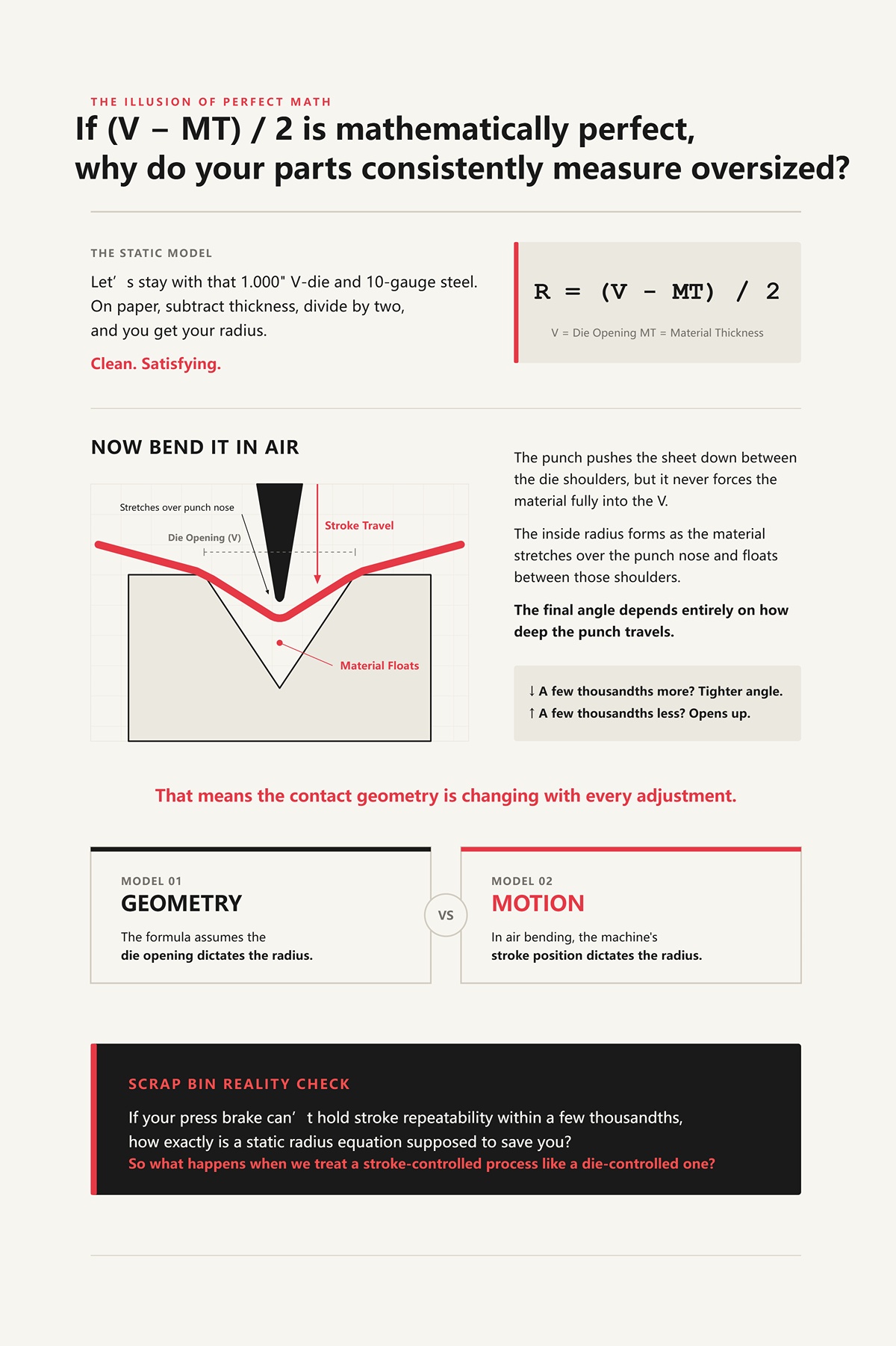
Let’s stay with that 1.000″ V-die and 10-gauge steel. On paper, subtract thickness, divide by two, and you get your radius. Clean. Satisfying.
Now bend it in air.
The punch pushes the sheet down between the die shoulders, but it never forces the material fully into the V. The inside radius forms as the material stretches over the punch nose and floats between those shoulders. The final angle depends entirely on how deep the punch travels. A few thousandths more stroke? Tighter angle. A few thousandths less? Opens up.
That means the contact geometry is changing with every adjustment.
The formula assumes the die opening dictates the radius. In air bending, the machine’s stroke position dictates the radius. Those are not the same model. One is geometry. The other is motion.
Scrap Bin Reality Check: If your press brake can’t hold stroke repeatability within a few thousandths, how exactly is a static radius equation supposed to save you?
So what happens when we treat a stroke-controlled process like a die-controlled one?
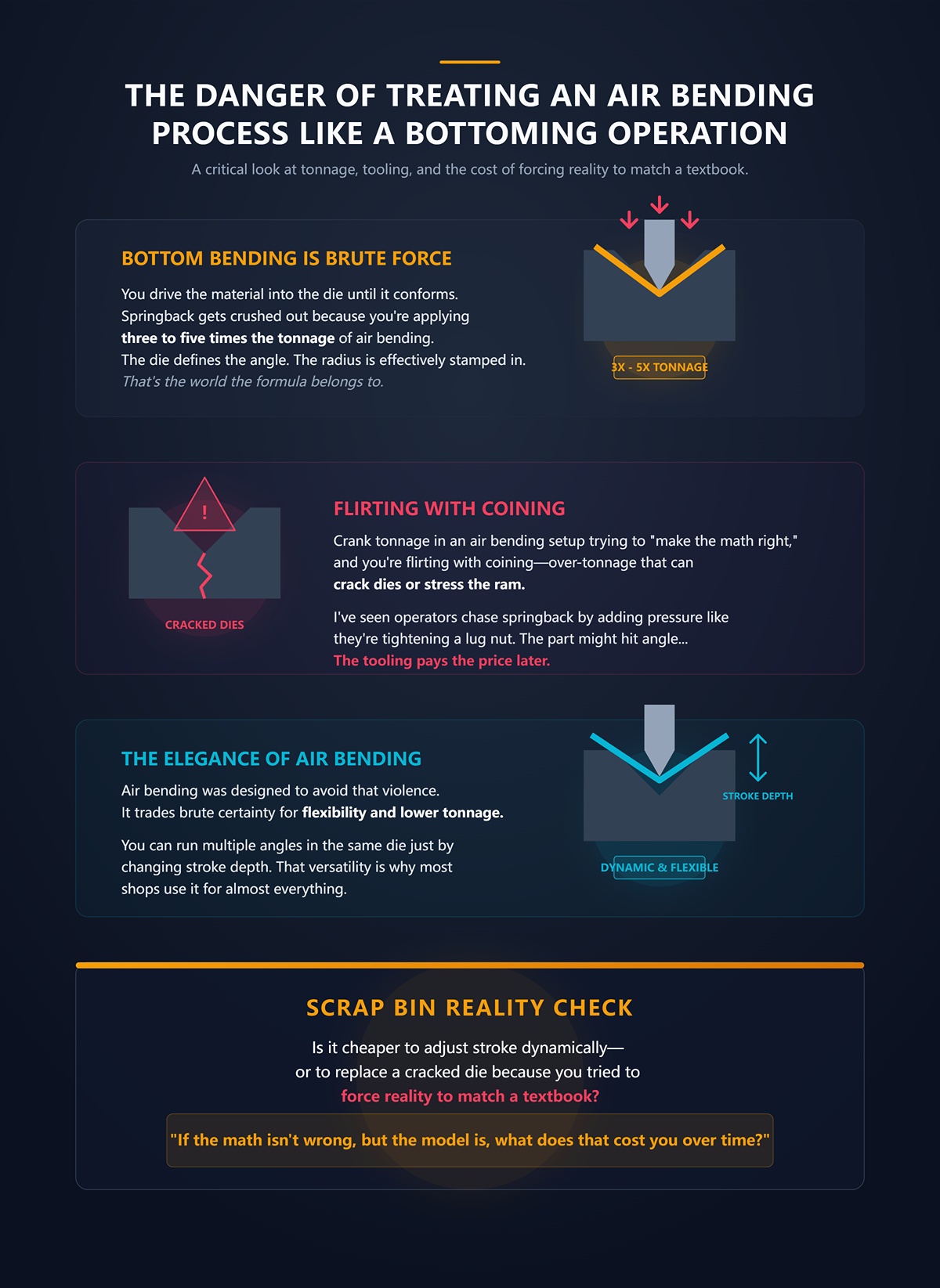
Bottom bending is brute force. You drive the material into the die until it conforms. Springback gets crushed out because you’re applying three to five times the tonnage of air bending. The die defines the angle. The radius is effectively stamped in.
That’s the world the formula belongs to.
But crank tonnage in an air bending setup trying to “make the math right,” and you’re flirting with coining—over-tonnage that can crack dies or stress the ram. I’ve seen operators chase springback by adding pressure like they’re tightening a lug nut. The part might hit angle. The tooling pays the price later.
Air bending was designed to avoid that violence. It trades brute certainty for flexibility and lower tonnage. You can run multiple angles in the same die just by changing stroke depth. That versatility is why most shops use it for almost everything.
And yet we’re still clinging to a formula built for the process we’re not using.
Scrap Bin Reality Check: Is it cheaper to adjust stroke dynamically—or to replace a cracked die because you tried to force reality to match a textbook?
If the math isn’t wrong, but the model is, what does that cost you over time?
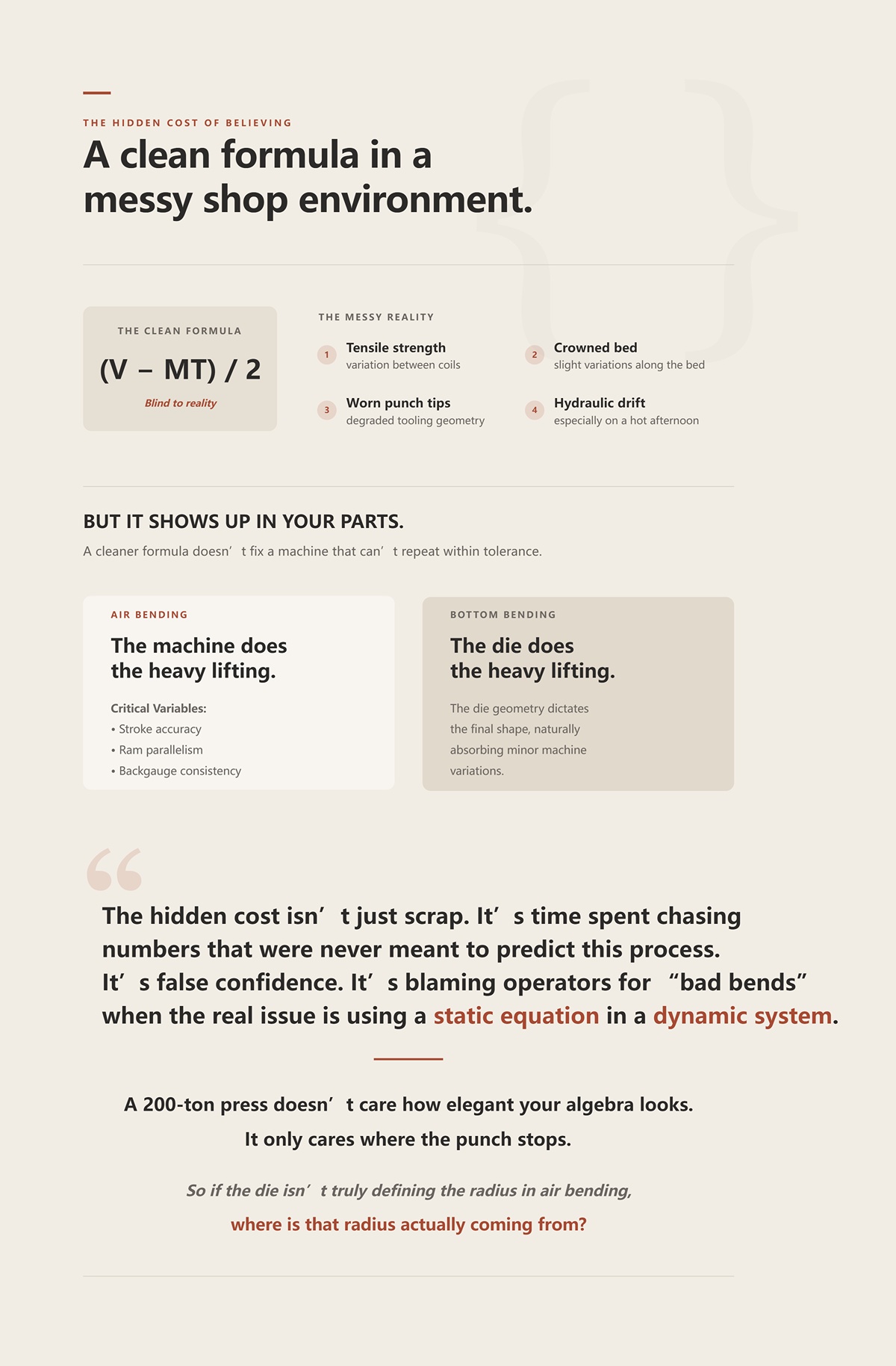
Here’s what the formula doesn’t see: tensile strength variation between coils, a slightly crowned bed, worn punch tips, hydraulic drift on a hot afternoon. None of that shows up in (V − MT) / 2.
But it shows up in your parts.
Air bending makes the press brake itself the critical variable. Stroke accuracy. Ram parallelism. Backgauge consistency. In bottom bending, the die does the heavy lifting. In air bending, the machine does. A cleaner formula doesn’t fix a machine that can’t repeat within tolerance. That’s why many shops move toward fully CNC-controlled systems designed for high-precision bending and automation—like those in the CN-HAWE press brake lineup—where control of stroke depth, parallelism, and repeatability becomes a measurable capability, not a guess.
The hidden cost isn’t just scrap. It’s time spent chasing numbers that were never meant to predict this process. It’s false confidence. It’s blaming operators for “bad bends” when the real issue is using a static equation in a dynamic system.
A 200-ton press doesn’t care how elegant your algebra looks. It only cares where the punch stops.
So if the die isn’t truly defining the radius in air bending, where is that radius actually coming from?
Take that same 1.000″ V-die and 10‑gauge 60‑KSI cold‑rolled steel. Measure the inside radius across ten parts bent in air. You won’t get 0.433″. You won’t get your punch tip radius either. You’ll land right around 0.160″ to 0.200″—roughly 16–20% of the die opening.
That percentage shows up so often it stops being coincidence.
Not because the die is magically stamping that number in. Not because the punch nose matches it. But because when the sheet sinks between the die shoulders, it finds a natural curvature based on how far it can span that opening under load. The die width sets the stage. The material tension sets how tightly it can bend across that span. The radius forms in midair, suspended between shoulders, controlled by penetration depth.
In air bending, the die opening—not your punch tip and not your calculator—is what establishes the baseline inside radius. Everything else rides on top of that.
If you’ve been chasing (V − MT)/2, you’ve been solving for the wrong mechanism.
I’ve stood over a 10-gauge bracket, 1″ V-die under it, because 10‑gauge at 0.135″ thickness times 8 gives you about 1.08″. Close enough. That 8× rule isn’t folklore. It keeps tonnage reasonable and usually lands you in a stable bending window.
Run the math forward instead of backward.
If 1.000″ V is in the ballpark for that thickness, and air bending produces an inside radius around 16–20% of V for 60‑KSI steel, you’re predicting 0.160″–0.200″ radius before you ever touch the ram. That’s already nowhere near (V − MT)/2.
Now tighten the die to 0.800″—about 6× thickness. Your natural radius drops to roughly 0.128″–0.160″. Open it to 1.250″—near 10×—and you’re floating around 0.200″–0.250″.
The ratio (8×, 10×, 12×) isn’t about elegance. It’s about controlling two things at once: tonnage per foot and the percentage-based radius that will emerge from that span. Go too narrow and tonnage spikes fast. Go too wide and your radius balloons whether the print likes it or not.
Scrap Bin Reality Check: Ever open the die “just to be safe on tonnage” and then wonder why your flange suddenly won’t fit the mating part? That wasn’t operator error. That was geometry scaling your radius whether you asked for it or not.
So if the die width sets the baseline percentage, what happens when the material itself resists bending harder—or softer—than your last job?
Swap that 60‑KSI cold‑rolled for 304 stainless in the same 1.000″ V. Same thickness. Same punch. Same programmed stroke depth to hit 90°.
Measure the radius.
It opens up.
Stainless carries higher tensile strength and work-hardens aggressively. As the punch drives down, the material fights the curvature more than mild steel. It won’t hug that 16% lower band as easily. You might see it drift toward 20% or slightly above. The metal is stretching under higher internal stress before yielding into that tighter arc.
Now drop in soft 5052 aluminum. Lower tensile strength. Lower yield. Less fight. It will sink deeper for the same penetration, often producing a radius closer to the lower end of the percentage band—or even slightly under in some cases.
Same die. Different multiplier.
That’s the shift most calculators ignore. They treat V as the only variable and thickness as a subtraction term. In reality, tensile strength shifts where inside that 16–20% window you’ll land. Stronger material pushes you toward the upper side of the range. Softer material lets you tighten up.
This is where thickness-based “1× material under 6 mm” rules sometimes appear to work in thin gauges. Thin mild steel in a properly sized die often lands near a radius close to thickness. But that’s alignment of variables, not proof of a universal law. Change strength or V-width and that neat 1× relationship disappears.
Scrap Bin Reality Check: How many times have you run stainless in a die that behaved perfectly for mild steel, only to chase angle and watch the radius grow anyway?
And if the punch tip isn’t what’s carving that arc, what role does it actually play?
Look at a 0.062″ punch nose under that same 1.000″ V. Bend 10‑gauge in air. Measure the part.
You won’t find 0.062″ inside.
The punch pushes the sheet down between the die shoulders, but it never forces the material fully into the V. Contact at the nose is localized. As penetration increases, the sheet wraps partially around the punch, then transitions into a free span between shoulders. The majority of the final inside radius is formed by that spanning action, not by the punch imprinting its shape like a stamp.
Penetration depth changes everything. A few thousandths deeper stroke increases wrap, reduces span length, and tightens angle—but the radius still resolves as a function of die width and material resistance. Unless you bottom or coin—where the material is crushed into full die contact—the punch tip is a driver, not a mold.
That’s why in proper air bending your punch radius should be smaller than the expected inside radius. It needs to initiate the bend without dictating it. If they match exactly, you’re either bottoming unintentionally or flirting with coining tonnage.
The press brake is a 200‑ton truth machine. It exposes whether your model matches the physics. In air bending, the physics says this: the die opening defines the baseline span, the material’s tensile strength shifts the percentage inside that span, and the punch only controls how deep you dive into that system.
If your print calls for a tight radius that your die ratio naturally wants to exceed, are you going to keep trusting a static formula—or are you going to change the die before the scrap bin votes again?
I’ve watched a 90° mild steel bracket come off the brake at 92° the second the ram lifted. Same die. Same program. Same operator. Under 200 tons, it was dead on. Five seconds later, it wasn’t.
That’s the question you’re really asking when the natural die-based radius doesn’t match the print: are you solving for what happens under load, or for what the customer measures after the load is gone?
The radius and angle you see while the punch is buried in the V are not the radius and angle you ship. The moment the pressure comes off, elastic strain releases. The outer fibers that were stretched try to shorten. The inner fibers that were compressed try to recover. The part opens up. That’s springback bite, and it doesn’t care about your clean little (V − MT)/2 calculation.
Scrap Bin Reality Check: Ever hit the angle perfectly on the depth readout, only to watch the inspector tell you every flange is 1.5° open? The steel didn’t disobey the screen. It obeyed physics.
Static calculators assume the geometry you formed under pressure stays put. It doesn’t. And if you don’t build compensation into the plan, you’re not predicting a finished radius—you’re predicting a temporary one.
So the real fight isn’t what radius you get at bottom stroke. It’s what radius survives unloading.
Picture 0.125″ cold‑rolled in a 1.000″ V. You drive to a depth that gives you 90° while the punch is down. Pull the ram up and you’re sitting at 91.5°. That means your under‑load angle was closer to 88.5°.
Now ask yourself: which angle did your formula predict?
If you calculated bend deduction, bend allowance, and flange lengths assuming a true 90° geometry without factoring that 1.5° springback, every flange is long. Not by much. Just enough to wreck an assembly.
Overbending is the blunt instrument we all use. Program 88.5° so it relaxes to 90°. But here’s the trap: that compensation is not constant across jobs. Open the die to 1.250″, and the same material may spring back 2° or more because the larger radius reduces plastic strain and leaves more elastic energy stored in the section. Thinner material? More springback. Larger inside radius? More springback. That relationship has been shown in cold‑rolled steel where springback grows with radius-to-thickness ratio, not just with strength.
So if you’re calculating bend deduction off a 90° nominal and then manually sneaking in 1.5° of overbend at the machine, you’ve just split your math in half. The flat pattern thinks one thing. The ram is doing another.
Which number is driving your geometry—the print angle, or the angle you actually program?
Swap that mild steel for 304 stainless. Same thickness. Same die. Same target angle.
You’ll see more springback. Everyone does. The instinct is to blame tensile strength because it’s the biggest number on the cert. Higher tensile, more fight, more opening.
But watch what happens when you run two heats of “the same” 60‑KSI steel. One bends sweet. The other springs back an extra degree. Tensile didn’t jump 10 KSI overnight. What shifted is the yield-to-tensile ratio—the yield ratio.
Springback is driven by how much of the deformation is elastic versus plastic. A material with a high yield strength relative to its tensile strength enters plastic deformation later and stores more elastic energy before it yields deeply. That stored energy is what kicks your angle open when the load comes off.
Geometry amplifies it. Larger die openings create larger inside radii. Larger radii mean lower plastic strain for the same angle. Lower plastic strain means a higher proportion of elastic recovery. That’s why radius bending with wide V-dies can spring back dramatically compared to tight 6× setups.
Scrap Bin Reality Check: Ever run a wide die to save tonnage, nail the angle on the screen, and then chase 3° of springback across a 10-foot part? That wasn’t bad luck. That was low plastic strain handing control back to elasticity.
So which moves the needle more—strength numbers on paper or the radius-to-thickness ratio you chose with your tooling? In practice, geometry sets the stage. Material properties decide how hard the recoil is.
And if that recoil changes, what happens to every flat pattern number you trusted?
Take a four‑bend channel. No return flanges. Each bend springs back 2°. That’s not dramatic. That’s normal in some stainless jobs.
Now stack it.
Four bends at 2° each means your last flange can be 8° out relative to the first reference if you never compensated correctly at each step. I’ve seen parts where the first article looked “close enough” per bend, but the cumulative error made the assembly twist like a propeller.
Bend deduction and K‑factor assume a known inside radius and a known final angle. If springback changes either and you don’t update the numbers, your neutral axis location shifts in reality but not in your software. The flat length you cut is based on a smaller arc length than what actually exists after relaxation. Multiply that across multiple bends and tolerances disappear fast.
This is why one-size-fits-all K‑factors are fantasy. Change die width, you change radius. Change radius, you change springback. Change springback, you change final angle and effective bend allowance. If your system doesn’t close that loop—measure relaxed angle and radius, feed it back into deduction—you’re cutting flats for a part that only exists under 200 tons.
The press brake is a 200‑ton truth machine. It tells you what the material will really do. The scrap bin is the final judge of whether you listened.
If the radius that survives unloading is the only one that matters, why are you still building flat patterns off the one that disappears the moment the ram lifts?
I’ve stood over a 10‑gauge bracket, 1.000″ V‑die under it, watching the first article come off at 92° when the print screamed 90°. Programmer swore the flat pattern was right. The calculator swore the inside radius was “exact.” The scrap bin didn’t care.
You want to know how to feed real springback back into your bend deduction and K‑factor so the flat matches the relaxed part. Good. Because until you close that loop, you’re not calculating—you’re gambling with plate.
Here’s the method I use on a 200‑ton truth machine that has no patience for pretty formulas.
Set a piece of 0.125″ mild steel over two dies: one 0.750″ V, one 1.000″ V. Same punch. Same angle target. The parts do not come out with the same inside radius. They can’t. The die opening sets the geometry of how the sheet is allowed to flow.
In air bending, the die opening largely governs the resulting inside radius. A common starting rule in the real world is 6:1 V‑to‑thickness for thinner mild steel, 8:1 as thickness climbs. So 0.125″ material? You’re usually in a 0.750″ to 1.000″ V. That ratio isn’t a suggestion—it’s the strain envelope. Too tight and you risk cracking. Too wide and you reduce plastic strain and invite springback bite.
Now look at what happens when someone starts from the print instead. “I need a 0.125 radius.” Fine. But if you choose a 1.250″ V to save tonnage, your natural air‑formed radius may land closer to 0.200″+ depending on material. No amount of wishful thinking changes that. Geometry already decided.
Scrap Bin Reality Check: I’ve seen shops force a wide die because it’s already in the machine, hit the angle on the screen, and then watch flanges grow long because the relaxed radius was bigger than the flat pattern assumed. The formula wasn’t wrong. The starting assumption was.
If die width sets the strain condition, why would you ever start with a target radius divorced from that die?
Once the die is chosen, now you’re allowed to talk math.
Air bending doesn’t drive the punch nose fully into the V. The punch pushes the sheet down between the die shoulders, but it never forces the material fully into the V. The sheet bridges. That bridging creates a predictable relationship between V‑opening and under‑load inside radius.
In mild steel, a common baseline is that the inside radius under load will fall somewhere around 16–20% of the V‑opening. So a 1.000″ V might produce roughly 0.160″–0.200″ radius while the ram is down. Not exact. A range. Because thickness, strength, and die shoulder radius all nudge it.
Notice what we just did: we tied radius to die width first, not to (V − MT)/2, and not to punch tip. The old (V − MT)/2 formula can spit out numbers that look precise, but if your V/T ratio shifts from 6:1 to 8:1, your strain distribution changes and that tidy output drifts from reality fast.
And this is still under load.
Baseline radius is a snapshot at 200 tons. The part you ship is the one after the ram lifts. So what happens when that stored elastic energy comes back out?
Take 0.125″ cold‑rolled in that 1.000″ V. Under load you measure 90°. Release it and you’re at 91.5°. That 1.5° springback tells you something deeper: the radius also grew.
When angle opens, inside radius increases. The neutral axis shifts slightly because the elastic portion of the strain recovers. Materials with higher yield strength relative to their tensile strength store more elastic energy before fully yielding. Stainless will usually kick back harder than mild steel in the same die. Aluminum can surprise you when the radius‑to‑thickness ratio climbs.
But here’s the part textbooks skip: springback scales strongly with radius‑to‑thickness ratio. Open the die wider, you increase the inside radius. Increase the radius, you lower plastic strain for a given angle. Lower plastic strain means a higher fraction of elastic recovery. More springback. It’s geometry amplifying material behavior.
So the compensation sequence goes like this:
Now update your bend deduction and K‑factor using the relaxed radius and final angle—not the under‑load geometry. That’s the closed loop. If your measured springback is 1.5°, your flat pattern must reflect the arc length of the part at 90° relaxed, not 88.5° under load.
Given that CN-HAWE’s product portfolio is 100% CNC-based and covers high-end scenarios in laser cutting, bending, grooving, shearing, for readers who want detailed materials, Brochures is a useful follow-up resource.
Scrap Bin Reality Check: I’ve watched four‑bend channels miss overall width by over 0.060″ because the programmer used a fixed K‑factor from a chart while the die ratio changed. Same material. Different V. Different relaxed radius. The math never knew.
If springback depends on both material properties and the radius you created with your die, why would a single static K‑factor survive every job?
Cut a 2″‑wide strip. Same thickness. Same grain direction as production. Bend it in the chosen die to your programmed overbend—say 88.5° if you expect 1.5° of springback. Measure the relaxed angle and measure the inside radius with proper gauges.
Now you have three real numbers: die width, relaxed angle, relaxed radius.
Feed those back into your bend allowance calculation. Adjust K‑factor until calculated flange lengths match the measured test piece. That calibrated K becomes valid for that material heat, that die, that thickness, that setup.
This is not guesswork. It’s controlled iteration. One strip sacrificed so a hundred parts survive.
And yes, machine specifics matter. Die shoulder wear, ram deflection, crowning settings—all of it influences what the part does. That’s exactly why the test bend must be done on the same machine, same tooling stack, same setup. You’re calibrating the entire system, not just a formula.
Because here’s the truth: even a good prediction chain can be sabotaged by variables you didn’t model.
So once you’ve locked in die ratio, baseline radius, springback compensation, and a validated K‑factor, what hidden factors are still waiting to knock your “perfect” flat pattern off by thirty thousandths—and how much material are you willing to waste finding out?
Given that CN-HAWE invests more than 8% of annual sales revenue in research and development. ADH operates R&D capabilities across press brakes, if the next step is to speak with the team directly, Contact us fits naturally here.
You’ve chosen the die. You’ve measured springback. You’ve tuned the K‑factor until the test strip matches the print.
And the production run still drifts.
This is where the 200‑ton truth machine earns its name. You can feed it clean inputs, calibrated radii, measured overbend — and it will still expose weak assumptions hiding in the metal itself or the hardware holding it. The formula doesn’t fail loudly. The parts just grow legs and walk out of tolerance.
Given that CN-HAWE’s customer base covers industries such as construction machinery, automotive manufacturing, shipbuilding, bridges, aerospace, for teams evaluating practical options here, Laser Cutting Machine is a relevant next step.
Perfect math survives only perfect conditions.
The problem is, nothing in a fab shop stays perfect for long.
So what’s left that can still move your radius after you’ve “done everything right”?
Steel isn’t isotropic. That’s textbook language for a simple shop reality: it bends easier one way than the other.
When sheet is rolled at the mill, the grains elongate along the rolling direction. Bend perpendicular to that grain and the material stretches across those elongated fibers. Bend parallel and you’re trying to open them like a zipper. Same thickness. Same die. Different springback bite.
I’ve watched 0.125″ stainless hit 90° dead on across grain — then kick back almost a full degree more with the grain in the same 1.000″ V. Nothing else changed. Same program. Same operator. Same calibrated K‑factor from the test piece.
The only difference was orientation.
Scrap Bin Reality Check: If your test strip was cut across grain but production blanks were nested with grain running the long way to “save material,” your overbend compensation is wrong before the first hit. The press doesn’t care what direction was cheaper to nest.
Modern machines with angle probes can auto-correct in real time. Good. That proves the point. If grain didn’t matter, they wouldn’t need to measure it every bend. But walk into almost any modern fab shop and watch what actually happens — plenty of brakes out there are still running without live angle correction, trusting yesterday’s numbers.
If the metal itself changes stiffness depending on direction, how can a static radius formula pretend the sheet has no memory of how it was born?
Here’s the move I see when angles open up more than expected: bump the tonnage.
More pressure feels like control. It isn’t.
In air bending, tonnage doesn’t directly set radius — die width does. The punch pushes the sheet down between the die shoulders, but it never forces the material fully into the V. You’re forming by geometry, not by brute force. Crank up pressure past what’s required and you don’t magically “lock in” the angle. You start flirting with bottoming, coining, and inconsistent strain along the bend line.
Now your calibrated air‑bend math is mixed with partial bottoming behavior.
Scrap Bin Reality Check: I’ve seen operators chase a half‑degree of springback by adding tonnage, only to create tighter angles at the ends and looser in the center because of subtle deflection and uneven contact. The parts looked fine off the brake. They didn’t assemble.
More force amplifies small setup flaws. Slight mis-crowning. Slight material thickness variation. Slight ram deflection. What was a predictable 1.5° springback becomes 1.2° here and 1.8° there. You didn’t fix the formula — you blurred the strain pattern.
If your compensation method only works at one specific pressure window, is it really compensation — or just luck inside a narrow band?
Your calculator thinks you’re bending in a 1.000″ V with sharp, consistent shoulders.
Go measure that die after two years of production.
Die shoulders wear. They mushroom slightly, polish smooth, open a few thousandths. A “1.000 inch” V might now behave like 1.020″ at the top contact points. That widens the effective V/T ratio. Wider ratio means larger under‑load radius. Larger radius means more springback.
Your math is still using yesterday’s geometry.
Then stack tolerances: a little left‑right misalignment in sectionalized tooling, a shim under one die segment, a clamp not fully seated. Now the bend line isn’t experiencing uniform conditions across its length. Your single K‑factor is trying to describe a moving target.
Scrap Bin Reality Check: When flange lengths start walking by twenty or thirty thousandths over a long part, shops blame the programmer. Half the time, a new die segment fixes it. The spreadsheet never had a chance.
Yes, newer up‑acting brakes and smarter crowning systems reduce historical deflection problems. Good machines shrink the error band. They don’t eliminate physics. Tooling still wears. Surfaces still deform under load. Steel still has grain.
The press brake is a stress test for your assumptions.
You can chase a universal radius formula for the rest of your career, or you can accept what the machine keeps telling you: radius is not a number you calculate once — it’s a condition you control, monitor, and correct.
So if grain shifts stiffness, tonnage muddies strain, and tooling geometry drifts over time, why are we still pretending one static equation can protect us from the scrap bin?
You don’t fix a shifting radius with a better calculator.
You fix it by building a system that assumes the press brake will lie to you unless you verify it.
I’ve stood over a 10-gauge bracket, 1,000 parts deep into a run, watching angles drift half a degree as coil hardness changed from the front of the skid to the back. The formula didn’t change. The V-die didn’t change. The material did. That’s when it clicks: you’re not solving for a number — you’re controlling a process that moves.
The press brake is a 200-ton truth machine. It exposes weak assumptions the way a tensile test exposes weak steel. If your “radius formula” only works when the stars line up — same heat, same grain direction, same die wear, same tonnage window — then you don’t have a formula. You have a coincidence.
So what does a system look like when it’s built for reality instead of theory?
Start with thickness jumps.
For mid-range plate — say 6 to 12 mm — you’ll often see inside radius land around 1.5× material thickness in air bending with common die ratios. Go above 12 mm and that radius can jump toward 3× thickness, even when you scale the V opening “correctly.” That’s not a rounding error. That’s non-linear behavior.
The (V − MT)/2 crowd treats material like it scales smoothly. Real steel doesn’t.
As thickness increases, you’re not just bending more material — you’re changing the strain distribution through the section. Neutral axis shifts. Required tonnage climbs. Springback increases because the outer fibers are storing more elastic energy. Same V/T ratio on paper, different internal stress picture under load.
Now layer in tensile strength.
A low-yield 5052 aluminum and a high-strength stainless in the same die opening will not spring back the same. The stronger material stores more elastic strain before yielding. That energy comes back at you when the punch lifts. If your radius math doesn’t know yield strength, it’s blind.
Scrap Bin Reality Check: I’ve seen two heats of “the same” A36 behave differently enough to move flange length by thirty thousandths over four bends. The spreadsheet said identical inputs. The parts said otherwise.
And we haven’t even touched hardware error. A tenth of a millimeter of die misalignment can throw your angle off more than half a degree. Your universal formula assumes perfect geometry. Your shop floor doesn’t.
If thickness tiers behave non-linearly, tensile strength shifts springback, and tooling alignment drifts daily, what exactly is that one clean equation supposed to represent?
You stop guessing and you start measuring.
Pick your standard die ratios — the ones you actually run every day. For each material grade and thickness range, cut test strips with grain noted. Air bend to a controlled angle. Measure inside radius after springback with radius gauges or optical inspection. Record actual overbend required to hit 90° free state.
Do this once per material family and thickness tier. Not once per job. Once per controlled condition.
Now you build a chart that says, for example (hypothetical numbers):
That chart is not theory. It’s scar tissue.
When new material comes in without certified tensile data, you bend a coupon and see what it does. Five minutes on the brake beats five hours reworking parts. If you do have yield numbers, good — compare them to your chart trends. Over time you’ll see patterns between strength and springback in your own machine, with your own tooling.
Scrap Bin Reality Check: Shops that skip this step end up “tuning” every first article live on production parts. That’s not flexibility. That’s gambling with sheet stock.
And here’s the part most miss: you must control the machine before you trust the chart. Daily backgauge verification. Tooling seated and cleaned. Check die width with pins, not assumptions. If your hardware drifts, your data rots.
A chart built on uncontrolled setup is just organized fiction.
So when the calculator asks for inside radius, are you typing a guess — or pulling from a database your press brake has already proven?
This is the mindset change.
The calculator is not wrong. It’s incomplete. It assumes you’ve already defined the physical world correctly — true die width, real material behavior, verified alignment. Most shops feed it nominal values and hope.
Process ownership means you define and defend those inputs.
You standardize V/T ratios instead of swapping dies randomly. You lock down which materials run in which openings. You document grain direction requirements on prints. You quarantine new heats until they pass a bend test. You treat angle deviation as a signal — not an annoyance to crush with more tonnage.
And you accept that there is no universal inside radius formula.
There is only your radius, in your dies, on your brake, with your materials — validated under load by a 200-ton truth machine that doesn’t care what the handbook said.
The one thing to carry forward is this: radius is not a number you calculate — it’s a behavior you characterize.
Once you see it that way, the question stops being “What’s the formula?” and becomes “Is my process tight enough that the formula even has meaning?”


