

He swore he did everything the same.
Same 90-degree program. Same 304 stainless. Same punch and die. But on the older hydraulic brake, his parts came out three degrees open. He leaned harder on the pedal, rode the stroke deeper, tried to “feel” it into place.
By lunch, we had a stack of shiny scrap that looked like expensive bookmarks.
So what changed?
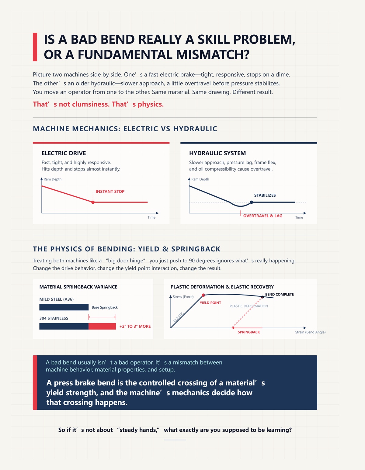
Picture two machines side by side. One’s a fast electric brake—tight, responsive, stops on a dime. The other’s an older hydraulic—slower approach, a little overtravel before pressure stabilizes. You move an operator from one to the other. Same material. Same drawing.
Different result.
That’s not clumsiness. That’s physics.
The electric drive hits depth and stops almost instantly. The hydraulic system builds pressure differently; there’s lag, flex in the frame, oil compressibility. That tiny difference changes how much the material actually yields before springback. With 304 stainless, which springs back 2–3 degrees more than mild steel like A36, that lag matters. A lot.
Treating both machines like a “big door hinge” you just push to 90 degrees ignores what’s really happening: you’re forcing material past its yield strength so it plastically deforms, then predicting how much it elastically springs back.
Change the drive behavior, change the yield point interaction, change the result.
A bad bend usually isn’t a bad operator. It’s a mismatch between machine behavior, material properties, and setup assumptions. A press brake bend is the controlled crossing of a material’s yield strength, and the machine’s mechanics decide how that crossing happens.
So if it’s not about “steady hands,” what exactly are you supposed to be learning?
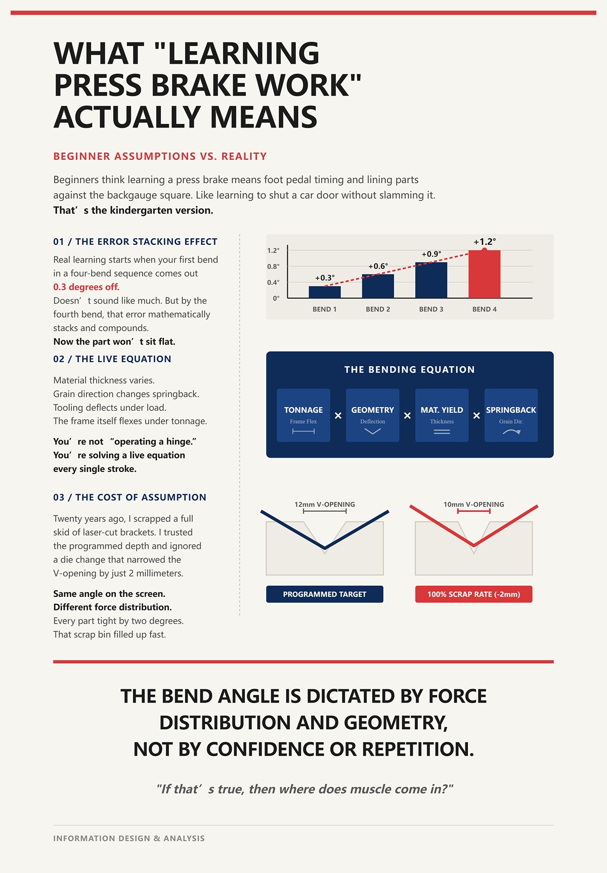
Beginners think learning a press brake means foot pedal timing and lining parts against the backgauge square. Like learning to shut a car door without slamming it.
That’s the kindergarten version.
Real learning starts when your first bend in a four-bend sequence comes out 0.3 degrees off. Doesn’t sound like much. But by the fourth bend, that error stacks. Now the part won’t sit flat. Even seasoned operators stop, recalculate ram depth, adjust backgauge, and manually tweak the program.
Why? Because the sheet didn’t read the textbook.
Material thickness varies. Grain direction changes springback. Tooling deflects under load. The frame itself flexes under tonnage. You’re not “operating a hinge.” You’re solving a live equation every stroke: tonnage × tooling geometry × material yield × machine deflection.
Twenty years ago, I scrapped a full skid of laser-cut brackets because I trusted the programmed depth and ignored a die change that narrowed the V-opening by 2 millimeters. Same angle on the screen. Different force distribution in the metal. Every part tight by two degrees. That scrap bin filled up fast, and it wasn’t because my foot slipped.
Learning press brake work means learning what variables move the metal—and which ones don’t care how experienced you are. The bend angle is dictated by force distribution and geometry, not by confidence or repetition.
If that’s true, then where does muscle come in?
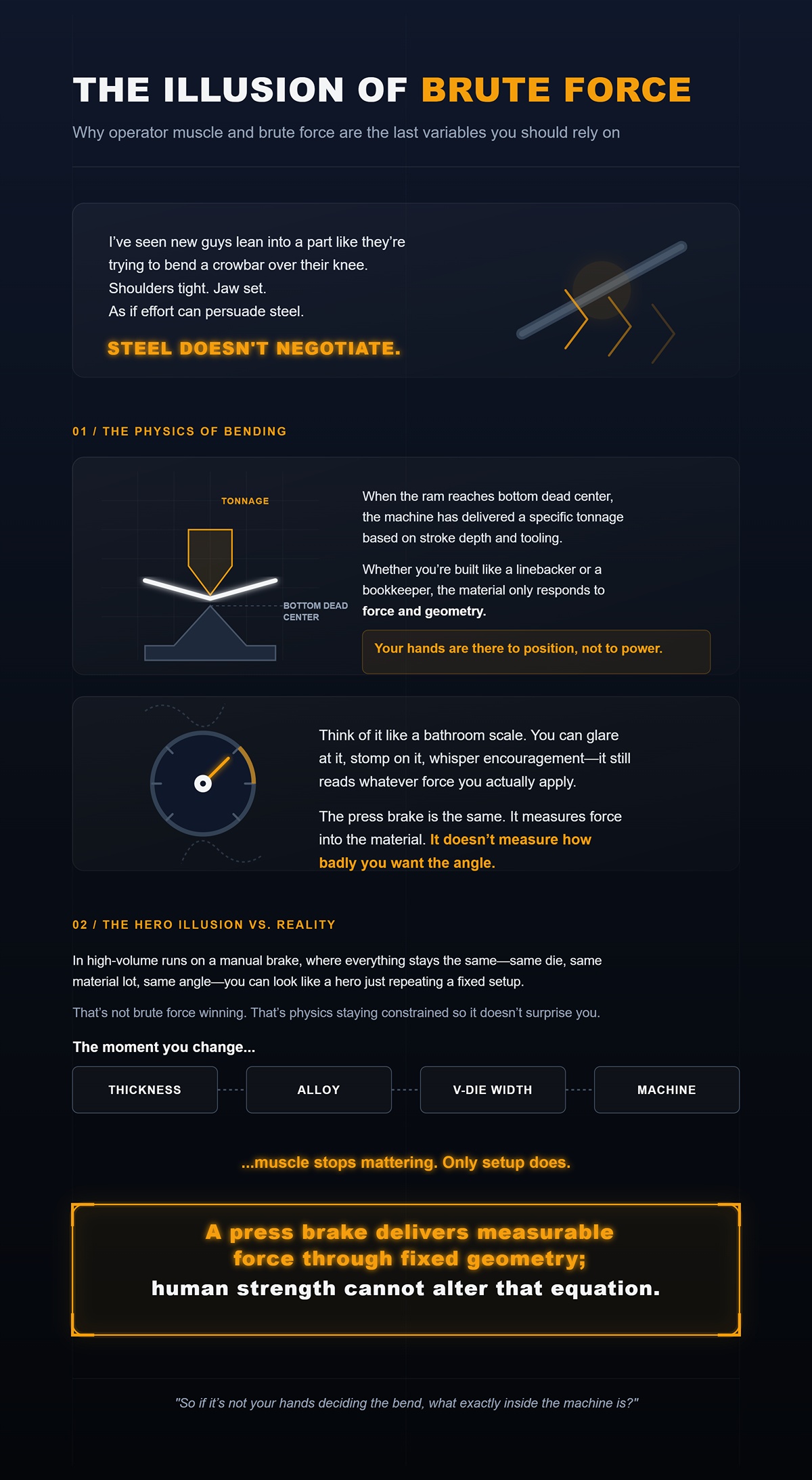
I’ve seen new guys lean into a part like they’re trying to bend a crowbar over their knee. Shoulders tight. Jaw set. As if effort can persuade steel.
Steel doesn’t negotiate.
When the ram reaches bottom dead center, the machine has delivered a specific tonnage based on stroke depth and tooling. Whether you’re built like a linebacker or a bookkeeper, the material only responds to force and geometry. Your hands are there to position, not to power.
Think of it like a bathroom scale. You can glare at it, stomp on it, whisper encouragement—it still reads whatever force you actually apply. The press brake is the same. It measures force into the material. It doesn’t measure how badly you want the angle.
In high-volume runs on a manual brake, where everything stays the same—same die, same material lot, same angle—you can look like a hero just repeating a fixed setup. That’s not brute force winning. That’s physics staying constrained so it doesn’t surprise you.
The moment you change thickness, alloy, V-die width, or machine, muscle stops mattering. Only setup does. A press brake delivers measurable force through fixed geometry; human strength cannot alter that equation.
So if it’s not your hands deciding the bend, what exactly inside the machine is?
You’re standing at the control, foot hovering, staring at 3 mm mild steel over a 24 mm V-die. One meter long. On paper, that bend needs right around 20 tons. Not 10. Not “about that.” Twenty. Double the thickness to 6 mm and you don’t double the tonnage—you roughly quadruple it.
That jump isn’t attitude. It’s math baked into the machine and the metal.
When you push the pedal, you’re not “bending steel.” You’re closing a system: ram moving down, bed holding steady, punch driving into the sheet, die resisting from below. Four pieces of hardened steel deciding where the force goes and how it spreads. Before your hands ever touch the sheet, the relationship between punch radius and die opening already limits what angle is even possible at a given depth.
So when you ask what inside the machine actually determines the bend, stop looking at your boots and start looking at those four parts.
Because they’re the ones doing the work.
Watch the ram on a long bend—say 8 feet of 4 mm steel. As it comes down under load, you can measure deflection at the center. A few thousandths of an inch. Doesn’t sound like much. But over length, that means the center sees less force than the ends unless you compensate with crowning.
That’s frame physics.
The ram is the moving beam. The bed is the fixed beam. When tonnage builds, both flex. Hydraulic machines build pressure through oil; there’s compressibility and a slight delay before full tonnage stabilizes. Electric drives hit position faster and hold tight, but they still load the frame the same way once tonnage climbs. Different feel. Same beam bending under load.
He swore he did everything the same.
But on the older hydraulic brake, his parts came out three degrees open.
What changed wasn’t his foot. It was how the ram delivered and stabilized force before the frame fully loaded. If the ram stops at depth before tonnage equalizes across the bed, the material never fully crosses yield in the center. You get variation across the part.
I once ignored worn gibs—those guide surfaces that keep the ram tracking straight. Under heavy load, the ram twisted just enough to bias one side. We ran 200 parts before checking angle side-to-side.
All scrap. Straight to the bin.
The ram and bed aren’t just “holding” the tooling. They’re opposing beams in a controlled flex system. If they deflect, the force distribution changes. If the force distribution changes, the yield line in the metal shifts. Force is only real at the point and moment it is evenly supported between ram and bed.
And if the force has to pass through those beams, what shapes it next?
Take a 12 mm V-die and swap it for a 16 mm V-die. Same punch. Same material. Same programmed angle.
Your bend angle changes.
Why? Because in air bending, the sheet only contacts the punch tip and the two die shoulders. That makes the die opening the base of a triangle. The punch radius is the apex. The angle that triangle forms at a given depth is geometry, not enthusiasm.
Press faster. Press slower. The triangle doesn’t care.
Beginners think speed “snaps” the metal into place. It doesn’t. Speed changes cycle time. Geometry sets the angle. With a wider V, the material sinks deeper before reaching the same included angle. That deeper penetration changes how much of the cross-section goes plastic versus elastic, which changes springback.
Twenty years ago, I narrowed a V-die by 2 mm without adjusting the program. Same screen angle. Same depth.
Every bracket came out tight by two degrees.
That wasn’t gremlins. A narrower die concentrates force over a smaller span, increasing penetration for the same stroke. More plastic deformation. Less springback. Different result. The geometry moved; the angle followed.
Think of it like splitting wood. A sharper wedge (narrower die effect) concentrates force and drives deeper for the same swing. A blunt wedge spreads it out. You don’t fix that by swinging harder. You fix it by choosing the right wedge.
In air bending, the final angle is dictated by the geometric relationship between punch radius and die opening at a specific penetration depth.
So if geometry is deciding the angle, why do some guys brag about “bottoming it out” like that’s real muscle?
Set up two jobs in 3 mm mild steel.
Job one: air bend to 90 degrees over a 24 mm V-die.
Job two: bottoming in a tight die where the punch forces the sheet fully into the die angle.
The air bend might need around 20 tons per meter.
Bottoming? Easily three to five times that, depending on material.
Air bending uses three-point contact. You’re forming a controlled arc and letting springback happen, then compensating for it with depth. Bottoming forces the material into full surface contact with the die angle. You’re not just crossing yield—you’re ironing the material into shape. That takes serious tonnage.
And here’s the twist: the process that needs less brute force—air bending—is the one most precision work uses.
Why? Because it’s adjustable. Small depth changes—thousandths of an inch—translate to tenths of a degree. You’re tuning penetration, not crushing the sheet into submission.
I watched a guy bottom thin stainless on a light-duty brake because he thought “harder equals accurate.” He overloaded the machine, deflected the frame, and ended up with inconsistent angles anyway.
Plus a service call.
Bottoming feels decisive. Air bending looks gentle. But precision favors controlled penetration over maximum force. The less surface contact you force, the less tonnage you need, and the more predictable the geometry becomes.
Which brings us to the instant that actually matters—the split second the metal gives up and yields.
Slow the stroke down in your head.
The punch tip touches the sheet. Nothing permanent yet—that’s elastic deformation. The metal is stretching on the outside surface, compressing on the inside, but it will spring right back if you stop.
Go deeper.
At a specific stress—its yield strength—the outer fibers can’t return. They plastically deform. That’s the point of no return. The inside is still mostly elastic at first. As penetration increases, the plastic zone grows through the thickness. Where that transition sits—called the neutral axis shift—depends on die width and punch radius.
Wider die? The neutral axis shifts differently. More springback.
Sharper punch? Higher localized strain. Less springback.
This isn’t philosophy. It’s stress distribution through a cross-section. Like bending a plastic ruler: the top turns white where it stretches past yield. That whitening is your yield line in real time.
If the ram stops before enough of the thickness goes plastic, elastic recovery dominates and the angle opens. If it goes deeper, more material stays permanently deformed and springback shrinks.
As if effort can persuade steel.
It can’t. Only stress exceeding yield at the correct depth, across the correct geometry, will lock in the angle. And that stress is delivered through ram, bed, punch, and die acting as a closed mechanical equation.
A bend becomes permanent only when applied stress exceeds yield strength across a sufficient portion of the material’s thickness—controlled by penetration depth and tooling geometry, not operator force.
Now that you see the four components and the exact moment the metal gives in, the next question isn’t about skill.
It’s about capacity.
How much tonnage does your machine actually have in reserve before this neat little equation turns into another trip to the scrap bin?
You want to know what inside the machine actually decides whether that bend happens clean or turns into scrap?
It’s not your stance at the foot pedal. It’s the force curve the ram can deliver, the frame’s stiffness under load, and how that force travels through punch, sheet, and die as a closed loop. The hydraulic cylinders (or servo ball screws on an electric) push down. The bed pushes back up. The frame stretches microscopically. The tooling concentrates that force into a narrow line. If any part of that chain is undersized for the math, the angle lies to you.
A few years back, a kid on second shift grabbed 6 mm mild steel and said, “Just dial up more tonnage.” He swore he did everything the same. Same punch. Same depth. Same machine. But he swapped to a narrower die because he wanted a tighter inside radius. Ten parts later, we had cracked edges and a groaning press brake.
That wasn’t a power problem. That was a geometry problem pretending to be a strength problem.
Let’s break the trap.
Take 3 mm mild steel. Put it over a 24 mm V-die. That’s the old rule of thumb—about 8× material thickness for air bending. Now swap that die for a 12 mm V because you “want it sharper.”
Watch what happens.
The narrower die reduces the span between contact points. Same ram force, but now that force is concentrated over a smaller width. Pressure—force divided by area—jumps fast. The material sees higher localized stress. Penetration increases for the same stroke. Springback drops. Sounds good.
Until you look at the tonnage chart.
For air bending mild steel, required tonnage per meter roughly follows:
Tonnage ∝ (Material Thickness²) ÷ V-die Opening
Thickness is squared. Die opening is in the denominator. Cut the V in half, and you nearly double the required tonnage.
That means your 50-ton brake that was comfortable over a 24 mm V might be flirting with its limit over a 12 mm V—even though the sheet thickness never changed.
I scrapped a batch of galvanized brackets years ago because I chased a tighter radius with a smaller die. The machine hit its tonnage limit mid-stroke, frame deflected, angles wandered two degrees across the length. Looked like operator error.
It was math.
The die opening doesn’t just shape the bend. It determines how much of your machine’s rated capacity you’re consuming. Required bending force rises as thickness squared and falls as die opening increases—geometry sets the load before your foot touches the pedal.
So what happens when you ignore that and just “send it”?
Overload a brake and it doesn’t explode like a cartoon. It lies to you.
When you exceed rated tonnage, the frame stretches—microns, but enough. The bed and ram deflect in the center. Your ends hit angle. The middle opens up. You shim. You tweak crowning. You chase ghosts.
Long term, you wear out pins, bushings, cylinder seals. The machine loses repeatability because it’s been flexed past its comfort zone too many times.
Now undersize tonnage—meaning you don’t apply enough force for the chosen die and thickness—and the failure looks different. The ram reaches programmed depth, but the material hasn’t gone plastic through enough of its thickness. You get heavy springback. Angles open three degrees. Operators start overbending randomly.
But on the older hydraulic brake, his parts came out three degrees open.
He blamed the hydraulics. Reality? He switched from A36 to 304 stainless and kept the same die and depth. Stainless has higher yield strength. It resists plastic deformation longer. Needed more force or more penetration. The machine delivered what it was told. The material didn’t yield as expected.
Overload failure distorts the machine. Under-tonnage failure distorts the part.
Both get blamed on “bad brakes” or “touchy material.”
Neither has anything to do with how hard you glare at the control panel. Exceed rated tonnage and the machine deflects; undershoot required tonnage and the material springs back—force must exceed yield without exceeding frame limits.
And that leads straight to the nose of the punch.
Grab a punch with a razor-sharp tip and run it into 4 mm aluminum over a narrow die.
You’ll see a bright line form along the outside of the bend. Then maybe a crack.
Why?
A sharp punch radius concentrates strain at the outer fibers. Remember that neutral axis shift we talked about? The smaller the inside radius, the more the outer surface must stretch. If the required elongation exceeds the material’s ductility—its ability to stretch before cracking—it fails.
It’s like bending a paperclip slowly versus kinking it hard at one point. The tighter the bend radius, the more localized the strain.
Now here’s where the tonnage trap tightens: a sharper punch often demands a narrower die to support that radius. Narrower die means higher tonnage requirement. Higher tonnage means higher stress in both material and machine.
I once ran high-strength steel with a punch radius too tight for its elongation rating. First part looked fine. Second had micro-cracks. Third split clean. Scrap bin got fed because I tried to “force” a radius the material physically couldn’t stretch into.
As if effort can persuade steel.
It can’t. The inside radius in air bending is largely a function of die opening, not punch sharpness alone. You don’t get to demand a 1 mm inside radius from 5 mm plate just because the punch tip is 1 mm. The material and die decide together.
Minimum achievable inside radius is governed by material ductility and die width—strain concentration, not operator will, determines whether it bends or breaks.
So how do you stop guessing and actually calculate what your brake can handle?
Let’s walk it clean.
Say you have:
A standard tonnage chart for air bending mild steel will list something around 20 tons per meter for that setup. That’s within range for a 50-ton, 2-meter brake—assuming even load and good condition.
Given that CN-HAWE operates more than 50 sales and service points in China and overseas. Its products are sold in more than 100 countries and regions, for readers who want detailed materials, Brochures is a useful follow-up resource.
Now change one variable.
Keep 3 mm thickness. Keep 1 meter length. Swap to a 12 mm V-die.
Chart jumps close to 40 tons per meter.
Nothing got thicker. You didn’t “ask for more bend.” You changed geometry. The equation responded.
Now change material.
Same 3 mm thickness. Same 24 mm die. But switch to 304 stainless.
Because its yield strength is higher, required tonnage increases—often 30–50% more than mild steel, depending on condition. Your comfortable 20 tons per meter might climb toward 28 or 30.
If your machine is rated 25 tons per meter across that length, you’re no longer safe. Not because you lack courage. Because the numbers don’t fit.
This is where green operators get trapped. They see tonnage as a big ceiling number on the machine badge. They don’t divide by bend length. They don’t adjust for die width. They don’t account for material yield.
They treat tonnage like horsepower in a pickup truck.
It’s not horsepower. It’s allowable force distributed across a span, governed by geometry and material properties. A strict equation.
And once you understand that the die opening, material yield strength, bend length, and thickness all feed into a calculable load, the next question stops being “Can I power through this?”
It becomes: how does this particular brake actually generate and control that force through its drive system—and how precisely can it hold it at the bottom of the stroke? That’s where machine design and verification matter. On a modern system such as a CN-HAWE press brake, frame and ram strength are validated through finite element analysis and built under a disciplined quality-control process, so the rated tonnage isn’t just theoretical—it’s force you can apply and repeat with confidence.
On a mechanical press brake, the ram is tied to a spinning flywheel through a crank. Once that clutch drops, the ram is coming down whether you like it or not. Full stroke. Fixed path. The tonnage curve peaks near bottom dead center because that’s where the crank geometry gives you maximum mechanical advantage.
On a hydraulic brake, two cylinders push the ram down with pressurized oil. Pressure builds as resistance builds. You can stop mid-stroke. You can dwell at the bottom. The force is whatever the hydraulic pressure times piston area says it is.
On an electric servo brake, ball screws driven by servo motors convert rotary motion to linear force. The control measures motor torque and position in real time. It knows exactly where the ram is and how much force it’s applying at that instant.
Same sheet. Same die. Same tonnage chart. Three completely different ways of delivering that calculated force.
And that difference is your margin of error.
The tonnage equation we just walked through doesn’t care about your attitude. It assumes the machine can deliver a specific force at a specific position and hold it there without overshooting, sagging, or coasting past the point where the material yields. If the drive system can’t control force and position together, your math is right and your part is still wrong.
That’s the hinge: the drive system is the mechanism that turns theoretical tonnage into real, controlled deformation. Force must be generated, positioned, and held in sync with material yield—control, not effort, determines accuracy.
I started on a mechanical. Big flywheel humming overhead like a ceiling fan that could kill you. You set your shut height, line up the die, and when you hit the pedal, that ram committed.
He swore he did everything the same.
New kid. Same 2 mm mild steel. Same 20 mm V-die. Same backgauge stop. First batch was fine. Second batch? Overbent by almost two degrees. What changed? He adjusted shut height a hair to “tighten it up.” On a mechanical, that tiny adjustment shifts where peak tonnage hits relative to bottom dead center. The crank keeps moving. There is no dwell. No pressure modulation. It blasts through yield and coasts.
That’s the danger. A mechanical brake delivers maximum force at a fixed geometric point in its rotation. If your die height, material thickness, or backgauge position is off, the machine does not compensate. It completes the stroke. As if effort can persuade steel.
I scrapped a stack of galvanized brackets because a mechanical brake doesn’t care about springback timing. No bottom dwell means the material begins elastic recovery the moment force drops. You get variability you can’t tune out without physically changing shut height and trying again. Scrap bin filled up fast that week.
And safety? Once engaged, that ram is coming down. A beginner misjudges setup, the machine doesn’t forgive. It commits.
Mechanical brakes aren’t obsolete because they’re weak. They’re obsolete because their force curve is locked to crank geometry. There is no dynamic control, only position-based force peak. When force delivery is fixed by linkage geometry, your margin of error shrinks to zero.
So what replaces that rigidity without turning the machine into a guessing game?
I watched trainees move from a modern electric brake to an older hydraulic. Same program. Same numbers. But on the older hydraulic brake, his parts came out three degrees open.
He blamed the hydraulics.
Reality? The electric servo had been bottoming, sensing torque spike, and holding position for a programmed dwell of 0.5 seconds. That dwell let the material fully yield before retract. The hydraulic was set up for faster cycle, minimal dwell. It hit depth and came back up. Material hadn’t fully stabilized under load. Springback bit him.
The drive system changed how long full tonnage was applied.
Hydraulics build force as pressure increases. If the system has good proportional valves and CNC control, it can ramp speed down near bottom, apply full pressure, and hold. That holding capability is forgiveness. Misjudge by a few tenths of a millimeter, and you can bump the depth and re-hit without committing to a full violent stroke.
Electrics measure motor torque directly. They’re brutally precise in position—often within microns. But they have lower peak tonnage in many models and rely on motor torque limits. For thin material and short flanges, they’re surgical. For 12 mm plate across a long bed, hydraulics still dominate because cylinders can generate and sustain massive force without overheating motors.
Given that CN-HAWE’s product portfolio is 100% CNC-based and covers high-end scenarios in laser cutting, bending, grooving, shearing, if the next step is to speak with the team directly, Contact us fits naturally here.
Now here’s where beginners get fooled: they think hydraulics are “softer” because oil compresses slightly. In reality, modern closed-loop hydraulics with linear encoders correct for that in real time. The forgiveness comes from controllable pressure and dwell, not from slop.
I once swapped 3 mm mild steel for high-strength plate on a hydraulic brake rated comfortably for the job. The first hit came up underbent. Instead of resetting hard stops like on a mechanical, I added 0.3 mm depth and a one-second dwell. Second part dead on. Scrap bin got only one piece instead of fifty.
Forgiveness isn’t magic. It’s the ability to adjust force and hold time without changing hard geometry. A drive that can modulate and sustain force at bottom dead center widens your setup tolerance.
But what about the machines that try to split the difference?
Hybrids use servo motors to drive hydraulic pumps only when movement is needed. You get hydraulic cylinders for force, but electric control over pump speed and energy use.
On paper, that sounds like the best of both worlds. And in high-mix shops chasing energy savings and noise reduction, it makes sense.
For basic brackets and enclosures? The physics doesn’t change. You still have cylinders pushing a ram. You still rely on pressure times piston area for tonnage. The hybrid advantage is efficiency and sometimes faster approach speed, not different force behavior at the bend line.
I saw a small job shop buy a hybrid thinking it would “solve inconsistency.” Their real problem was mismatched dies and ignoring tonnage per meter. The new machine was quieter. More efficient. The parts were still wrong until they fixed their math.
Hybrids don’t rewrite the equation. They refine how power is supplied to the same hydraulic mechanism. If your work lives under 6 mm mild steel and moderate bend lengths, complexity doesn’t buy accuracy by itself.
The question isn’t “Is it modern?” It’s “Does it control force and position precisely enough for your load range?”
Because the last piece isn’t just forgiveness. It’s repeatability.
Cycle time tells you what the machine values.
Mechanical brakes are fast once engaged. Flywheel stores energy. Bang—stroke complete. Great for repetitive shallow bends where tooling and material never change. Terrible when you need controlled depth variation.
Hydraulics can approach fast, slow near contact, press, dwell, retract. That segmented motion is programmable. Repeatability depends on encoder quality and frame rigidity, but modern CNC hydraulics will hit depth within hundredths of a millimeter all day—if maintained.
Electrics shine in short-stroke, high-repeat jobs. No warm-up for oil. No valve lag. Position is direct from servo to screw. For thin stainless panels, I’ve seen electrics hold angle variation tighter than older hydraulics simply because there’s less fluid dynamic delay.
But here’s the ceiling: electric systems often have lower maximum tonnage for large beds. Hydraulics dominate heavy plate because they can sustain 250 metric tonnes and beyond without cooking motors. Mechanical can deliver high peak force, but not with adaptive control.
Your drive system sets two hard limits: maximum controllable force and minimum controllable increment of position. That’s your accuracy window.
Choose wrong, and you’ll either fight springback you can’t dwell against, or crawl through cycles because your heavy hydraulic is overkill for 1 mm aluminum.
The machine is a scale and a lever system. It only responds to measurable inputs—pressure, torque, position. Pick the drive that can generate and hold the force your equation demands, within the positional tolerance your part requires.
Because once that ram comes back up, the material isn’t done talking. It springs.
You asked the right question: if the machine can hit depth within hundredths of a millimeter, why does the angle change after the ram comes back up?
Because steel isn’t clay.
When the punch drives into the V-die, the outer fibers of the sheet stretch and the inner fibers compress. At bottom dead center, some of that deformation is permanent — we’ve crossed the yield point — but not all of it. Part of it is elastic, like a stretched rubber band hiding inside the bend. The moment the pressure releases, that elastic portion snaps back, opening the angle a degree or three depending on the material.
That snap is springback.
I’ve watched a kid stare at a perfect 90 under load, grinning like he solved the universe. Ram comes up. Now it’s 92. He swore he did everything the same. He did. The machine did too. The metal just finished its sentence after the tool stopped talking.
Here’s the part you need burned into your skull: precision at full force does not guarantee precision after unloading. The drive system can control force and position with surgical accuracy, but once the force goes to zero, the material’s yield strength decides how much it recovers. That recovery isn’t opinion. It’s physics.
Think of it like bending a plastic ruler over the edge of a table. Push it to 90, let go, and it springs open. Push it past 90, let go, and maybe it settles where you want. You don’t argue with the ruler. You push past the target on purpose.
That “past” is not guesswork. It’s compensation.
And that leads to the first practical question every brake operator has to answer.
You never aim for 90 if you want 90.
You aim past it.
How far past depends on yield strength — the stress where material stops acting like a spring and starts acting like it’s permanently bent. Mild A36 might spring back one degree. 304 stainless? Two, sometimes three. That’s not personality. That’s higher yield strength storing more elastic energy before it gives up.
I once had a batch of stainless brackets come off at 88 when we programmed 90. Instead of checking the certs, the operator kept nudging depth blindly. Five parts later, scrap bin had a neat little fan of shiny mistakes. We measured the first bend properly, saw it was springing back 2.5 degrees, programmed a 92.5 target, and the next run locked in. One measured adjustment would’ve saved the pile.
Here’s what’s happening under the hood: when you overbend, you’re forcing more of the cross-section past yield so that when the elastic portion relaxes, what remains is your intended angle. Too little overbend and it opens up. Too much and you crush the inside radius or over-stress the grain.
So how much?
You measure the first part with a digital protractor. You compare target versus actual. You adjust ram depth accordingly. Modern CNC controls even let you program springback compensation directly. But that first piece still tells the truth. Not your gut.
Because springback is proportional to yield strength and bend geometry, not to your confidence at the control panel.
Now you might be thinking — fine, I can overbend. Problem solved.
Not quite.
Picture a long bookshelf sagging in the middle under heavy textbooks.
That’s your press brake under load.
When you’re bending a long part, the ram and bed deflect slightly in the center because that’s where the force is concentrated. Even a heavy frame moves a little under 200 tons. The result? The middle of your part sees less effective penetration than the ends.
So the ends hit 90 under load. The center hits maybe 89. Then you release. Everything springs back — but unevenly. Now your ends are 92 and your center is 94.
You didn’t change material. You didn’t change depth. The machine flexed.
Crowning systems — mechanical wedges or hydraulic compensation along the bed — pre-load the center upward to counteract that bow. You’re intentionally bending the machine opposite the expected deflection so that under full tonnage it straightens out.
No crowning on a long, heavy bend is how you quietly build a stack of “almost right” parts that won’t sit flat in assembly. I scrapped a 2-meter enclosure panel years ago because I trusted the tonnage chart and ignored bed deflection. Beautiful finish. Wrong geometry. Scrap bin doesn’t care how shiny it is.
The rule here is simple and brutal: frame deflection changes effective bend depth, and effective bend depth controls springback outcome.
So even if your drive system is perfect, the structure carrying that force has a say.
And structure isn’t the only hidden variable.
Yes.
Roll a sheet through a mill and you stretch the grain structure along the rolling direction. Bend parallel to that grain and you’re bending along the fibers. Bend perpendicular and you’re bending across them.
It’s like splitting firewood.
Hit with the grain, it opens easy. Across the grain, it fights you.
When you bend perpendicular to the grain, you often get slightly more resistance and sometimes more springback. The difference isn’t massive in thin mild steel, but in high-strength materials it’s enough to throw off a tight tolerance if you pretend it doesn’t exist.
I had a run of parts that behaved one way in prototypes and another in production. Same thickness. Same spec. Only change? The blanks were nested differently, so the bend line rotated 90 degrees relative to the rolling direction. First production batch came out wide on angle. Scrap bin got fed until we caught the orientation change.
Grain direction doesn’t rewrite the equation, but it tweaks the constants. Ignore it, and your “perfect” compensation drifts.
Because material anisotropy — directional properties from rolling — slightly shifts yield behavior and therefore springback.
Now let’s talk about the material that really tests your honesty.
High-tensile steel is the better liar.
Mild steel bends and mostly stays put. Its lower yield strength means less stored elastic energy at the same geometry. You overbend a degree or so, it settles close.
High-tensile stores more energy before yielding. Under load, it looks obedient. Ram up, and it opens like a bad promise.
I switched from 3 mm mild to a high-strength plate once without changing the springback compensation. But on the older hydraulic brake, his parts came out three degrees open. Same depth. Same tooling. Different yield strength. That’s when the apprentice looked at me as if effort can persuade steel.
It can’t.
304 stainless typically springs back a couple degrees more than mild. Advanced high-strength steels can be worse. The stronger the material, the more it behaves like that plastic ruler fighting to return straight.
So which lies most?
The stronger one.
Because the higher the yield strength, the greater the elastic recovery after unloading.
And that’s the reality check: even with perfect force control, perfect position, and rigid tooling, the metal still gets the last word when the pressure disappears.
So the real question isn’t “Can my machine hit depth?”
It’s this: are you thinking in terms of force, structure, and material behavior as one equation — or are you still hoping the steel will just stay where you pushed it?
You want to know how to predict springback before you start feeding the scrap bin.
Good. That’s the right question.
Here’s the carry-forward: stop asking “How much will this metal spring back?” and start asking “What elastic energy am I storing in this geometry on this machine?” Springback isn’t a personality trait of 304 stainless or high-tensile plate. It’s the visible result of stored elastic strain energy unloading when the punch lets go. If you control the energy going in — through force, V-die width, punch radius, material thickness, and actual machine deflection — you control the angle that comes back out.
That’s not obvious because most beginners treat springback like weather. You check a chart. You hope.
Charts don’t know your machine’s frame stretch at 180 tons across 8 feet. Charts don’t know your die shoulders are worn .2 mm on one side. Charts don’t know your blank was cut across the grain this time. You do.
So the new model is this: the press brake is a calibrated lever-and-wedge system. The metal is a spring you are partially yielding. Your job is to measure and standardize the inputs that determine how much elastic energy remains when you unload. Not guess the output.
Once you see it that way, the question changes from “What’s the right overbend?” to “How do I lock down the variables so the overbend is predictable every time?”
When you say “I’m bending metal,” you picture pushing something until it stays put.
That image is wrong.
You’re driving a wedge (the punch) into a controlled opening (the V-die), using a lever system (the ram and frame), to exceed yield strength in a narrow zone while leaving elastic energy in the surrounding material. That’s mechanics, not muscle.
I once watched a kid reef on the control, chasing depth by feel. He swore he did everything the same. Parts still came out open by a degree and a half. He blamed the steel. I tore down the setup. Different V-die than the last job — 16 mm instead of 20 mm. That changed the inside radius, which changed the strain distribution, which changed the elastic recovery. We scrapped half a skid before he stopped treating it like arm-wrestling and started treating it like geometry. Scrap bin lesson: if you change die width, you changed the equation whether you admit it or not.
Here’s the practical shift: you standardize setups the way a machinist standardizes tool offsets. Same material spec. Same thickness batch. Same grain orientation. Same V-opening rule (for example, 8× thickness for mild steel — hypothetical baseline). Same punch radius. Record actual springback from the first validated part, not the first hopeful one.
Then you build a shop-specific springback table. Not from a handbook. From your machine, your tooling, your suppliers.
Because springback is proportional to stored elastic strain energy, and stored energy is set by force, geometry, and material properties — not by operator effort.
Once you’re managing energy instead of “bending,” prediction stops being mystical. It becomes repeatable. But repeatable inside what limits?
Blueprint says 90 degrees.
Machine says, “Under what conditions?”
This is where green operators get burned. They design the bend sequence around the drawing, not around the brake’s capacity and behavior.
Your checklist before the first hit:
Why 80%? Because as you approach max tonnage, frame deflection grows nonlinearly. Your effective penetration changes more per ton. That means your springback compensation per thousandth of ram depth becomes touchier.
I scrapped a run of long channels because I chased a tight inside radius on a brake that was simply too light for the length. We were running at the ragged edge. The center floated. The ends bit hard. Every adjustment fixed one and ruined the other. Scrap bin doesn’t negotiate with physics.
Design around the machine and the machine behaves. Design around the print alone and you fight invisible movement.
And here’s the non-obvious part: if you standardize tonnage range, die width ratio, and material batch for a product family, your springback compensation becomes a fixed offset plus a fine trim — not a daily experiment.
Because repeatability comes from operating inside a stable force envelope where machine deflection and material response stay consistent.
But what if the envelope itself is wrong?
There’s a moment you have to admit it.
If you need tight, repeatable radii in high-strength material across long lengths, and you’re bottoming near max tonnage every cycle, the problem isn’t your compensation math.
It’s machine selection.
Manual brakes shine on simple, repeated bends where setup stays fixed. CNC brakes handle complex sequences because they remove human repositioning error. But neither can cheat capacity. If your part demands coining force and your frame was built for air bending, you’re storing energy in places you don’t control — in the machine itself.
That’s when you stop tweaking offsets and start asking whether a heavier-frame brake, a different drive system, or even a different forming method makes sense.
I learned that the expensive way on a batch of thick stainless brackets. We kept adding overbend. Kept fighting springback. But on the older hydraulic brake, his parts came out three degrees open once the oil warmed and response changed slightly. Same program. Different dynamic behavior. We were trying to make a mid-range brake act like a coining press. Scrap bin filled up while we pretended persistence was a strategy.
Here’s the lens I want you to carry forward:
A press brake is not a bending tool. It is a force delivery system with structural limits. Your part either fits inside that system’s predictable range — or it doesn’t.
When you evaluate a job, don’t ask, “Can we bend this?”
Ask, “Can we control the force, geometry, and deflection tightly enough that springback becomes a fixed, measured offset instead of a moving target?”
Because precision is the byproduct of controlled force within machine limits — and no amount of operator grit overrides that equation.
Now you’re not just bending parts.
You’re deciding whether the physics will cooperate before you ever hit the pedal.


