

I walked into a shop three months after they’d installed brand-new light curtains on every press brake. Yellow posts, clean wiring, OSHA paperwork framed on the wall. I looked down at the emitter on the worst offender and saw a strip of masking tape over three beams.
They weren’t hiding it.
In a field evaluation of over 100 hydraulic press brakes, 92% of light curtains were intentionally bypassed within months of installation. Not hacked by engineers. Defeated with tape. Cardboard. A jumper wire across the terminals. That number shouldn’t make you angry at operators.
It should make you nervous about your design.
A few years back, I investigated an amputation on a 10-foot brake running thin stainless. The shop had a compliant light curtain. The operator had taped off the lower beams so he could “float” small parts into the die without constant nuisance trips. His sleeve brushed the punch during a slow inch cycle. He lost two fingers before the ram hit bottom.
The curtain worked exactly as installed. It just didn’t fit the way the job was actually done.
Here’s the uncomfortable part: when a safeguard adds friction—extra resets, awkward reaches, blocked visibility—the operator will remove the friction. The fastest way is to bypass the device. On most systems, that’s as simple as placing cardboard in front of the receiver to keep the beam “made,” or jumping the safety relay during setup. No malicious intent. Just production pressure.
So the real question isn’t whether your light curtain meets code.
It’s whether it’s faster to use than to defeat.
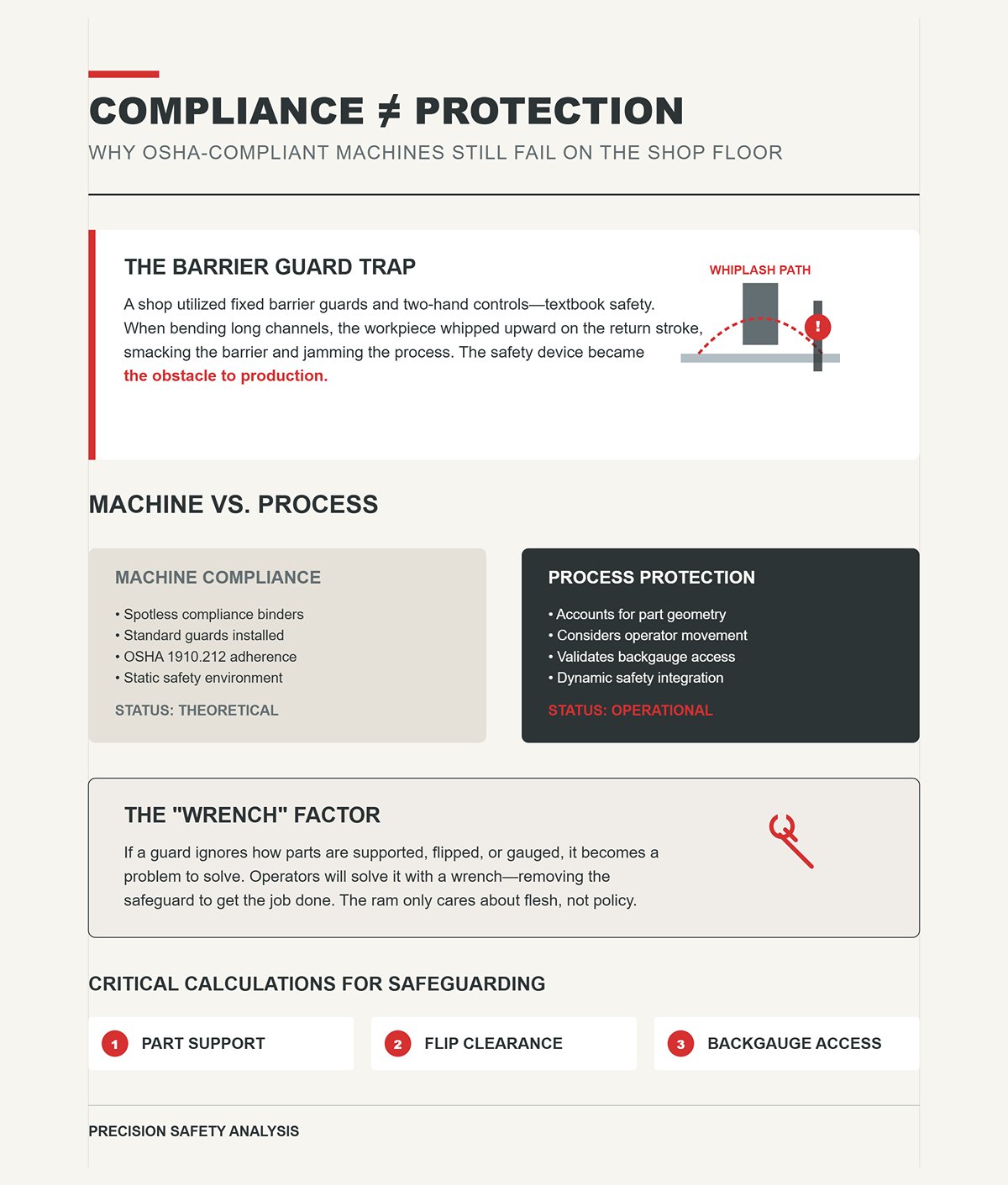
I’ve seen brakes with spotless compliance binders and hands still inside the die space during cycling. One shop had fixed barrier guards and two-hand controls—textbook safe. Until they started bending long channels. The workpiece whipped upward on the return stroke, smacked the barrier, and jammed. Operators removed the guard “just for this job.” It never went back on.
The machine was compliant. The process wasn’t.
OSHA 1910.212 doesn’t care how elegant your policy is. The ram only cares whether flesh is between punch and die. If your safeguarding strategy ignores how parts are actually supported, flipped, and backgauged, the guard becomes the problem to solve. And the operator will solve it with a wrench.
That’s why “compliant” and “protected” aren’t synonyms on a brake.
What are we really calculating when we set these systems up?
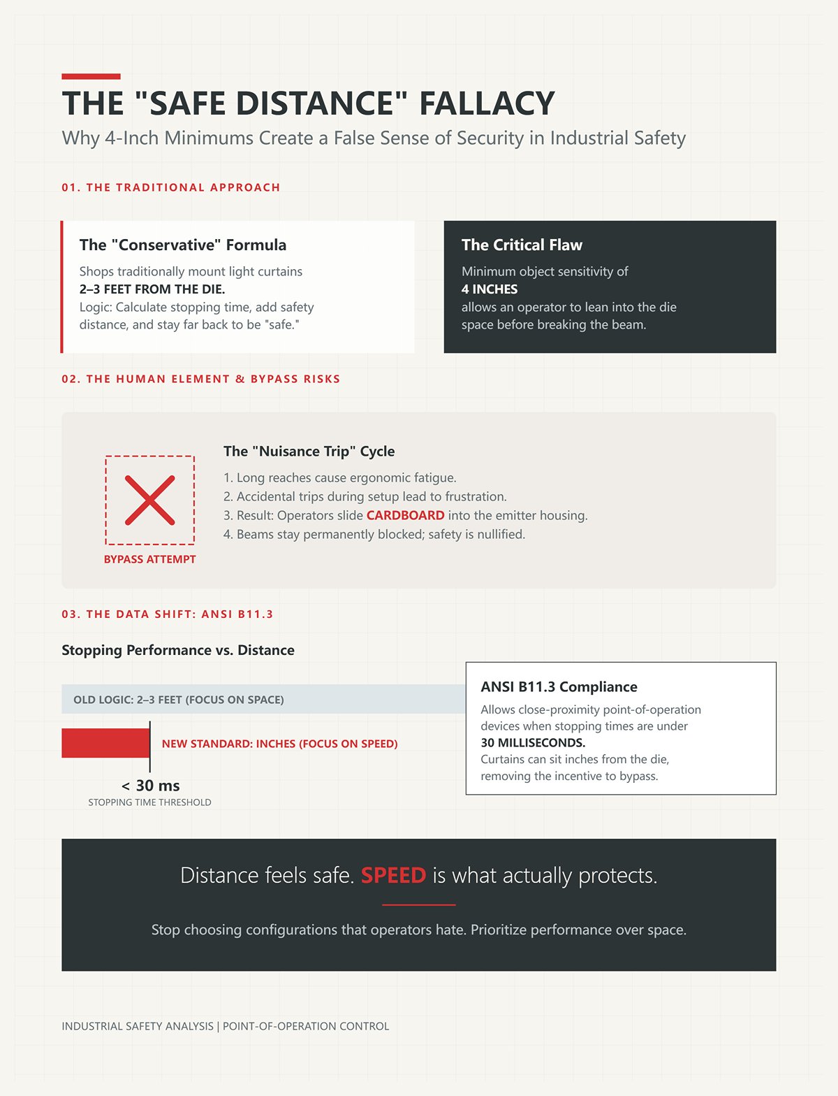
Most shops mount light curtains 2–3 feet from the die because that’s how they were taught: calculate stopping time, add safety distance, stay conservative. I’ve audited brakes where the minimum object sensitivity was 4 inches, set far enough back that an operator could easily lean into the die space before breaking the beam.
On paper, it satisfied the formula.
On the floor, it created a habit: step inside the curtain during setup, hold the part in place, then inch the ram. After a week of nuisance trips and long reaches, someone slides a piece of cardboard into the emitter housing so the beams stay blocked permanently.
Here’s what changed in recent years: ANSI B11.3 allows close-proximity point-of-operation devices when stopping times are under 30 milliseconds. That means curtains can sit inches from the die, not feet away. The old “safe distance” logic often ignores actual stopping performance and defaults to space instead of speed.
Distance feels safe. Speed is what actually protects.
So why do shops keep choosing the configuration that operators hate?
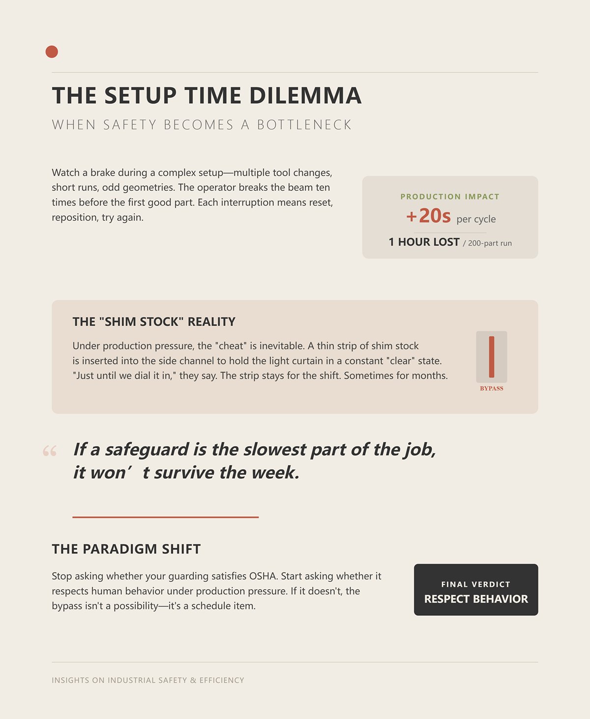
Watch a brake during a complex setup—multiple tool changes, short runs, odd geometries. The operator breaks the beam ten times before the first good part. Each interruption means reset, reposition, try again. If that adds even 20 seconds per cycle on a 200-part run, you’ve just burned over an hour.
Now put that operator on piece rate, or under a supervisor staring at the board.
I’ve seen the cheat play out the same way: during setup, someone inserts a thin strip of shim stock into the side channel to hold the light curtain in a constant “clear” state. “Just until we dial it in.” The strip stays for the shift. Sometimes for months.
Safety didn’t fail because the operator was reckless. It failed because it became the slowest part of the job.
And if a safeguard is the slowest part of the job, it won’t survive the week.
That’s the shift I need you to make: stop asking whether your press brake guarding satisfies OSHA, and start asking whether it respects human behavior under production pressure. If it doesn’t, the bypass isn’t a possibility.
It’s a schedule item.
A few winters back, I investigated a crush injury on a 12-foot hydraulic brake running deep box sections. The shop had installed a fixed barrier guard set back 2–3 feet from the die to satisfy calculated safety distance. On the third bend of a four-hit sequence, the operator had to support one flange while sighting the bend line on the other. The barrier blocked his body position, so he reached around it. The ram descended during an inch cycle. Three fingers flattened between punch and die.
The guard stayed bolted in place. His fingers did not.
That scene is what we’re really talking about when we ask why operators “sabotage” safeguards. Not laziness. Not stupidity. A physical mismatch between how a complex bend actually happens and how the safeguard assumes it happens. If the safe position and the productive position are different places, the operator will stand in the productive one.
So what actually happens at the point of operation that designers miss?
Watch a simple 90-degree bend in thin mild steel and you’ll think guarding is easy. Two hands on the blank, backgauge sets depth, ram cycles, part drops. Clean.
Now swap that for a 14-gauge stainless box, 36 inches long, four bends, tight inside radii. On bend two, one flange wants to tip downward from gravity. On bend three, the previously formed sides hit the punch holder unless the operator “floats” the part at a slight angle. On bend four, he’s inside the profile, fingertips within an inch of the die shoulders, because that’s the only way to keep the legs square.
The choreography changes every hit.
During that sequence, the operator’s hands are not parked in a textbook-safe zone. They slide, pivot, lift, and re-grip within fractions of an inch of the tooling. If you mount a light curtain 2–3 feet out because the stopping time formula said so on a slow mechanical brake, you’ve just forced him to lean through empty space before he can even touch the work. That reach becomes normal. Breaking the beam becomes constant. Reset becomes muscle memory.
And once reset becomes the slowest motion in the cycle, he will defeat it.
The most common cheat on fixed barriers with interlocked gates? A rare-earth magnet slapped onto the non-contact safety switch to fake a closed condition. I’ve pulled more than a few out of electrical cabinets. The operator doesn’t see himself as bypassing safety. He sees himself as removing a device that doesn’t understand the dance his hands have to perform.
Which raises a harder question: are some of the guards we call “safer” actually creating new blind spots?
On older friction-clutch mechanical brakes with long stopping times, you don’t have the luxury of close placement. Physics is physics. If the ram takes 200 milliseconds to stop, the calculated safe distance pushes the light curtain well away from the die. That’s why you see installations sitting 2–3 feet back.
Compliant. And ergonomically absurd for precision work.
I audited one plant where every complex setup required the operator to step inside the light curtain during inching because the curtain was too far out to allow proper part alignment. The “temporary” solution was a jumper wire across the safety relay during setup. They kept a pre-stripped piece of 14-gauge wire in the top drawer of the control cabinet. That’s not rebellion. That’s adaptation.
Now compare that to newer hydraulic brakes with monitored valves and stopping times under 30 milliseconds. ANSI B11.3 allows close-proximity devices in those cases. I’ve seen proximity systems that let an operator work within 4 mm of the danger zone at full approach speed, slowing automatically as the punch nears material. No long reach. No nuisance trips. No reason to cheat.
Same process. Different ergonomic math.
Best-in-class shops prove this isn’t fantasy. Facilities that integrate close-proximity guarding, automatic muting during safe portions of travel, and real stop-time measurement routinely post higher OEE and lower injury rates than shops running taped curtains and fixed rails. When the safeguard matches the hand motion, production goes up. When it fights it, production finds a way around it.
So if the technology exists to reduce friction, why do so many floors still train operators to defeat what’s installed?
Picture a brake cell with a whiteboard tracking daily output. Quota in red. Actual in black. It’s 2:30 p.m., and they’re behind.
The operator is running short batches—40 parts here, 60 there. Every setup breaks the light curtain ten, fifteen times while he dials in backgauge and tonnage. Each interruption costs maybe 15 seconds. On a 60-part run with multiple hits, that’s real time. An hour disappears across a shift.
No supervisor says, “Bypass the guard.” They don’t have to. The system says it.
I’ve watched a lead operator show a new hire how to defeat a poorly placed light curtain by sliding a thin strip of cardboard into the emitter housing so the lower beams stay made. “Only during setup,” he says. By second break, it’s still there. By Friday, it’s standard practice.
That’s training.
What are we really calculating when we set these systems up? Not just stopping distance. We’re calculating whether the fastest path to quota runs through the safeguard or around it. If going around it saves ten seconds a cycle, the floor will discover that before first break.
This is the friction point: when the ergonomic reality of the bend collides with the mechanical reality of the guard and the economic reality of the schedule. If those three aren’t engineered together, production weight will overpower the control—like a loaded truck with undersized brakes on a downhill grade.
So the question isn’t whether operators will adapt.
It’s whether we’re finally ready to design guarding that adapts first.
A 10 mm high‑tensile plate split mid‑bend on a hydraulic brake I reviewed after the fact. Brittle fracture. The stored spring‑back energy turned that half plate into a steel shovel moving faster than a man can blink. It cleared the front of the machine and hit the operator in the chest before anyone understood what happened. There was a light curtain installed. It was mounted at a calculated safe distance of 2–3 feet per ANSI B11 stop‑time math. Perfectly compliant.
It didn’t matter.
The beam was never broken because his hands weren’t the hazard. The workpiece was.
That’s the hole in single‑device thinking. If your only protection strategy is “don’t let hands enter the zone,” you’ve ignored tooling failures, material behavior, and gravity. What are we really calculating when we set these systems up? Not just stopping distance — we’re calculating how many different ways energy can reach flesh when the ram comes down.
Layering means this: no single defeated or outmatched device exposes the point of operation. Presence sensing handles hand intrusion. Physical barriers handle ejection and whip. Control logic forces operator engagement. Each covers the blind spots of the others.
If one layer fails — or gets cheated — the others still stand.
That’s what guarding looks like when it’s built around motion and physics instead of paperwork.
I investigated a mechanical power press amputation where the operator had “parked” a strip of shim stock in the lower light curtain channel so the bottom beams stayed made. The curtain sat 2–3 feet out because the measured stop time demanded it. To align small brackets, he had to lean inside the field constantly. Reset time slowed the cycle. So he defeated it the cleanest way possible: block the lower beams permanently and work above them.
They weren’t hiding it.
OSHA data shows nearly half of mechanical power press injuries end in amputation. That’s not trivia. That’s what happens when stopping time and safety distance push presence sensing far enough away that the operator must choose between reach and rhythm.
Now compare that to a modern hydraulic brake with verified 30 ms stop time and monitored valves. ANSI B11 allows close‑proximity presence sensing in those cases. I’ve seen systems that let operators work within 4 mm of the tooling during fast approach, automatically shifting to slow speed near mute points. No long reach. No nuisance break. No incentive to jam metal into a receiver channel.
Same concept — presence sensing.
Different ergonomic outcome.
The question isn’t “light curtain or laser PSD?” It’s this: does your bending profile require hand‑held part support within inches of the die? Long flanges that sag? Box parts that trap hands inside geometry? If yes, a far‑field curtain will create constant interruptions, and the exact cheat will be either a shim in the emitter, cardboard taped over lower beams, or a jumper wire across the safety relay during setup.
If your stopping time forces distance, and distance forces reach, and reach forces bypass — the device is wrong for the profile.
So when is a beam not enough?
| Topic | Details |
|---|---|
| Title | Presence Sensing Devices (PSDs) vs. Light Curtains: Which Actually Fits Your Bending Profile? |
| Real-World Incident | Operator bypassed a light curtain on a mechanical power press by placing shim stock in the lower channel so beams stayed made. Curtain was positioned 2–3 feet away due to required stopping distance. To align small brackets, the operator had to lean inside the field repeatedly, slowing cycle time and leading to deliberate defeat of the safeguard. |
| OSHA Data | Nearly half of mechanical power press injuries result in amputation, often linked to stopping time and safety distance issues that push presence sensing devices too far from the hazard point. |
| Root Problem | When stopping time requires increased safety distance, operators must choose between reach and productivity, increasing the likelihood of safeguard bypass. |
| Hydraulic Brake Comparison | Modern hydraulic press brakes with verified 30 ms stop time and monitored valves allow close-proximity presence sensing per ANSI B11. Operators can work within 4 mm of tooling during fast approach, with automatic shift to slow speed near mute points. |
| Ergonomic Difference | Both systems use presence sensing, but hydraulic systems allow close, uninterrupted work without long reach, nuisance trips, or incentive to bypass safeguards. |
| Key Question | Not “light curtain or laser PSD?” but whether the bending profile requires hand-held support close to the die. |
| High-Risk Applications | Long flanges that sag, box parts trapping hands, or operations requiring hands within inches of tooling create frequent interruptions with far-field curtains. |
| Common Bypass Methods | Shim in emitter, cardboard over lower beams, or jumper wire across safety relay during setup. |
| Core Principle | If stopping time forces distance, distance forces reach, and reach forces bypass — the safeguarding device is wrong for the bending profile. |
| Central Question | When is a beam not enough? |
A 12‑foot brake running heavy channel threw a formed leg upward when the punch cleared. The operator was hand‑holding near the die shoulders. The part whipped like a springboard and crushed three fingers against the punch holder. There was a light curtain. His hands were technically outside the field when the whip happened.
The hazard wasn’t entry. It was reaction.
Any time you’re bending thick plate, high‑strength material, narrow die openings, or parts with stored torsion, you have projectile or whip potential. That’s when a physical barrier — fixed or interlocked — becomes non‑negotiable. Not for compliance. For containment.
But here’s the trap Rockford and others have documented: fixed interlocked gates combined with two‑hand control often fail on press brakes because operators must hand‑support parts. If the barrier blocks that motion, they will defeat the interlock with a rare‑earth magnet on the coded switch or tape the actuator in place to fake a closed condition.
I’ve pulled magnets off more than one guard door.
So the barrier has to be placed where material can move but bodies cannot. Side shields for ejection paths. Rear guarding for backgauge zones. Adjustable front screens that block projectile vectors but leave hand access coordinated with presence sensing.
Barrier for flying steel. Presence sensing for wandering hands.
Different layers. Different jobs.
Which leaves one more weak link: the operator’s own initiation of motion.
Years ago, I saw a two‑hand control system defeated with a 3‑inch C‑clamp. The operator clamped one palm button down and ran the other with his free hand while steadying a narrow blank near the die. The anti‑tie‑down timing was old and sloppy. Cycle time mattered more than symmetry.
Two‑hand control isn’t about keeping hands busy. It’s about forcing conscious engagement before the ram moves. Modern controls require concurrent actuation within fractions of a second and release between strokes. Done right, they prevent “one‑hand‑and‑reach” behavior during single‑stroke operations.
But on a press brake running varied bend sequences, two‑hand control alone is usually impractical for production parts that require support. That’s why it must integrate with presence sensing and control logic — for example:
If you install two‑hand controls without integrating them into real cycle logic, the cheat will be simple: clamp, tape, or wedge one button and run the other.
Layered correctly, two‑hand controls enforce deliberate initiation when risk is highest — setup, adjustment, troubleshooting — while presence sensing manages dynamic hand motion during production bends.
Now step back.
Presence sensing protects space. Barriers contain energy. Two‑hand controls govern intent.
Remove any one, and a bypass or a failure can expose flesh to force. Combine them correctly, and defeating one layer still leaves protection standing.
That’s what a braking system on a loaded truck looks like: service brakes, engine braking, air systems, driver input — all engineered together so gravity and weight don’t decide the outcome.
The next problem isn’t choosing the layers.
It’s configuring their timing, muting, and control integration so production can’t quietly rewire them back into a single point of failure.
A few years back I audited a brake that “had all the right stuff” — laser presence sensing, programmable mute, foot pedal tied into a safety PLC. On paper it was textbook. On the floor, the mute window was set to stay open from 12 mm above the sheet all the way through 40 mm of travel because someone didn’t want nuisance trips on warped blanks.
Twelve millimeters of approach. Forty millimeters of blind travel.
At that point you haven’t installed protection. You’ve programmed the machine to ignore a hand.
That’s the line you have to hold when you configure these systems: every millisecond of muting and every millimeter of blanking must match the physics of the bend, not the impatience of the schedule. If the safe state slows production more than a bypass would, the operator will beat you with tape, magnets, or a jumper wire across the safety input.
So the job isn’t “turn on laser.” It’s this: make the protected cycle faster and smoother than the cheat.
How do you actually do that without choking throughput?
Stand at the side of a brake during fast approach. The punch drops at high speed until it gets near the work. That’s where presence sensing earns its keep — because hands are usually there, steadying material.
ANSI B11.3 ties safety distance to stopping time. If your verified stop time is 30 ms and your safety distance is calculated correctly, you can work close. I’ve seen systems allow guarding within 4 mm of the tooling during fast approach because the stopping performance supports it.
Now look at what happens when you program a mute window that opens at 15 mm above material to “make sure it doesn’t trip early.”
Fifteen millimeters at fast approach speed can be dozens of milliseconds of travel. If your stop time plus valve response is 30 ms, and the ram is moving, say, 100 mm per second in that phase (hypothetical but realistic for controlled approach), that’s 3 mm of travel during stopping. Fine — if the system is live.
But if you’ve muted it 15 mm early, you just created a 15 mm unprotected zone. The math no longer matters because the sensor is blind by design.
I investigated a partial amputation where the operator supported a narrow flange. The mute engaged too early due to a conservative CNC setting meant to accommodate bowed stock. His fingertips drifted forward as the punch transitioned from fast to slow. No trip. The window was still open.
He didn’t defeat the system.
We did, with bad configuration.
The rule is simple and brutal: the mute window must open no earlier than the minimum distance required to avoid false trips, and it must close the instant the non-hazardous phase ends. If your material variability forces you to widen that window, you don’t “tune it out.” You fix material handling or add support so hands don’t need to live in that zone.
Otherwise you’ve built a brake pedal that only works when the truck is already stopped.
If the mute window is one vulnerability, what about the times we tell the sensor to ignore space on purpose?
I walked up to a 10‑foot brake where the operator had taped off the lower beams so he could “float” small parts into the die without constant nuisance trips. He wasn’t hiding it. The tape was bright blue.
But here’s the part that bothered me: the CNC already had a programmable blank‑out tied to the backgauge position. It was set to ignore a rectangular zone in front of the die to accommodate box flanges.
The taped beams were just the final step. The system had already normalized ignoring that area.
Blanking has a legitimate use. Complex parts with side flanges or return legs will intrude into the sensing field. If you don’t blank those regions, you can’t run the part. Fair.
But blanking must be geometry‑specific and stroke‑specific. If your program says, “Ignore everything 0–50 mm above the die across the full width,” you’ve recreated the flaw of a fixed barrier that blocks good work and tempts bypass — except now it’s invisible and programmable.
And it’s not just the front zone. IRSST’s work on hydraulic brakes shows rear and side access points are real hazards during multi‑sided operations. If your front laser is carefully tuned but the side zone is unguarded, operators will pivot around the brake to support long parts from the flank. The path of least resistance becomes the unprotected path.
Safety that slows the front but leaves the side open doesn’t remove risk. It redistributes it.
So here’s the practical configuration rule: blank only the exact intrusion profile required for that bend, and tie it to tool and program memory with validation. If tool ID or backgauge reference is lost, the system should default to no blanking, not full blanking. Yes, that means nuisance trips during a fault.
That’s the point.
If recovery from a fault requires a supervisor code and a conscious reset, it’s still faster than an amputation report and a six‑week shutdown.
Which brings us to the most abused input on the machine.
I’ve seen a dual palm button plus foot pedal arrangement that required both hands down and the pedal depressed to initiate stroke. On paper, airtight.
On the floor, cycle time went to hell. Operators started wedging one palm button with a block of aluminum and running the other by hand while feathering the pedal. Anti‑tie‑down timing was tight — but a solid wedge doesn’t blink.
When you force three limbs to agree before every stroke on a production brake that needs constant hand repositioning, you create ergonomic drag. Drag creates workarounds.
The foot pedal should not be a third interlock layered on top of two‑hand control during production bending that requires hand support. That’s what presence sensing is for. The pedal’s job is intent — a deliberate initiation once the sensing system confirms hands are clear.
Here’s how it survives the floor:
Now the operator doesn’t have to fight the controls. He positions the part, the laser confirms safe space, and one natural foot motion starts the cycle. Faster than taping a beam. Faster than wedging a button.
If you make the protected cycle the smoothest path, most operators will take it. Not because they love OSHA.
Because they love rhythm.
And that rhythm is exactly what will erode your careful configuration over time if you don’t measure it.
I walked into a plant in April where we had commissioned a pristine press brake cell in January. Stopping time measured. Safe distance calculated. Laser aligned. By the time I came back, the ram overran its original stop by just enough to matter, the die set had changed twice, and the blanking window was still programmed for the first job. On paper, nothing had changed. In steel and hydraulics, everything had.
That’s the 90‑day decay.
OSHA lists machine guarding in its top ten citations every year. Yet there’s roughly one compliance officer for tens of thousands of workers. Most systems don’t fail because an inspector showed up. They fail because production pressure is heavier than the brake system you installed to control it.
Guarding isn’t a one‑time install. It’s a dynamic system, like the air brakes on a loaded truck. Pads wear. Linkages stretch. Drivers adapt. If you don’t measure and adjust, the stopping distance creeps past the safe line long before anyone notices. So the real question isn’t “Did we install it right?” It’s “Who is checking that it’s still right after 30,000 cycles and three tooling swaps?”
On a hydraulic brake, I’ve measured stopping time drift from 30 milliseconds at install to 42 milliseconds six months later. Doesn’t sound like much. Do the math.
Safe distance for presence sensing devices is based on stopping time plus a safety factor. ANSI formulas translate milliseconds into millimeters. If your original calculation put the laser at 100 mm from the hazard zone, that extra 12 milliseconds can push your required distance past 110 mm depending on approach speed assumptions. If the transmitter is still mounted at 100, you are now under‑spaced.
No one moved the guard.
The machine simply takes longer to stop because valves age, seals wear, and oil temperature changes response time. What are we really calculating when we set these systems up? We’re calculating a snapshot of physics on that day, with that fluid, with those components.
I investigated a crushed fingertip case where the presence sensing device was mounted correctly—based on a stopping time study done three years prior. The maintenance log showed brake work, but no follow‑up measurement. The operator didn’t defeat anything. The system drifted out of spec, and no one re‑ran the test.
If you aren’t performing periodic stopping time verification with a calibrated stop‑time meter—and adjusting safe distance when it changes—you’re driving a downhill load with brake pads you never inspect. So who owns that measurement in your shop: maintenance, engineering, or nobody?
A supervisor once told me they were “safe distance compliant” because this was “custom work.” I asked how many of that bracket they ran last month. He said 3,000. OSHA allows safe distance guarding without a physical barrier only for limited custom runs—more than one part, but no more than four hours per month of the same part. This wasn’t custom. It was production dressed up as job shop.
That’s not operator behavior. That’s classification creep.
Tooling swaps are another slow leak. New die height changes the pinch point elevation. Gooseneck punch replaces a straight punch, and suddenly the intrusion profile into the laser field changes. If your blanking zone was tied to the old geometry and nobody validates it, you either get nuisance trips—or worse, an oversized blanked area.
And here’s how the cheat happens when guarding doesn’t adapt: the operator will widen the programmable blank‑out zone in the CNC so the part clears without trips, then leave it that way for the next job. He won’t think of it as bypassing. He’ll call it “making it run.”
I’ve also seen the physical version. On a turret punch, a limit switch confirming the guard was closed was bypassed with a sliver of metal. The guard looked closed. The safety circuit thought it was closed. It wasn’t functional. Single‑point failure, invisible from ten feet away.
When OSHA cites these cases under 29 CFR 1910.212, they don’t care whether the guard was never installed or never updated. Same violation. Which raises the harder question: is your guarding modular and self‑checking enough to survive routine tooling changes without someone remembering a checklist?
Not a clipboard walk‑through. A functional test.
Start with stopping time measurement. Document the current value. Compare it to baseline. If it increased, recalculate required safe distance and verify the presence sensing device is mounted at or beyond that number. If your calculation says it now needs 115 mm and you’re at 100, you don’t argue with the math. You move hardware.
Next, validate every program‑specific blanking and muting window against the actual tool set installed. Physically load the tool ID. Confirm the CNC recognizes it. If tool ID is missing, the system should default to no blanking. Yes, that causes trips. That’s cheaper than blood.
Then test anti‑tie‑down and anti‑repeat on dual controls. Attempt the exact method an operator would use to cheat it—holding one palm button down with a block, riding the foot pedal, cycling rapidly. If the safety PLC doesn’t fault, you have a design problem, not a discipline problem.
Finally, review production classification. If a “custom” job has been running weekly for months, safe distance alone likely isn’t defensible. Engineering controls must match actual volume, not the story we tell about it.
OSHA requires periodic inspections but doesn’t define the interval. Monthly is practical. Ninety days is long enough for brake wear, software edits, and tooling drift to stack up into a gap wide enough for a fingertip.
Guarding that was faster than bypass in January can become slower by April if it’s tripping more, drifting out of tolerance, or mismatched to tooling. And when it becomes slower, the shop will correct it the only way it knows how.
The next question isn’t whether decay happens.
It’s whether your system is designed to detect its own drift before a human hand does.
I was called into a shop where a brand‑new laser guarding system had been installed six months earlier. On paper, it was top tier—tool recognition, programmable blanking, fast cycle speeds. On the floor, the stop‑time study hadn’t been re‑run after a hydraulic valve replacement. The required safety distance had crept past 100 mm, but the transmitter was still mounted at the original location. No alarms. No flashing lights. Just physics waiting its turn.
That’s the problem you’re actually solving.
Not “are we compliant,” but: what mechanisms force this system to expose its own drift before flesh does? If you don’t build in automatic detection or hard administrative triggers, 90‑day decay wins every time. So here’s the framework I use when a plant manager tells me, “If we had to fix this starting tomorrow, where do we begin?”
You don’t start with new hardware.
You start with stopping time ownership.
Someone—by name—must own quarterly stop‑time measurement with a calibrated meter. Not “maintenance as a department.” A person. Because safe distance isn’t a sticker; it’s a calculation tied to actual deceleration. If your brake drifts from 30 ms to 42 ms and no one recalculates, your presence sensing device is a decoration.
Second, you eliminate single‑point silent failures.
If the system allows tool changes without forcing tool ID confirmation, that’s a design flaw. If blanking zones can be widened without supervisor login or audit trail, that’s a design flaw. If the control doesn’t fault when stopping time exceeds the value used in its safe‑distance parameter, that’s a design flaw. Modern systems can lock cycle speed until a new stop‑time value is entered. That’s not fancy. That’s survival.
Third, you audit where OSHA violations actually cluster—point of operation exposure under 29 CFR 1910.212—and you assume your highest‑volume jobs are the most likely to drift out of spec. Not your custom one‑offs. Production work breeds normalization.
Why start there?
Because if drift isn’t mechanically or digitally visible, every other improvement rests on memory and goodwill.
I investigated a case where a shop installed fixed barrier guards with two‑hand controls—textbook compliant. The parts were long channels. They flexed. Operators had to support them near the die. So what happened? They removed the side panels and ran in “setup mode” all afternoon. They weren’t hiding it.
That’s what happens when compliance ignores ergonomics.
OSHA will accept two‑hand control if it keeps hands outside the hazard zone, typically requiring separation distance calculated from stopping time and hand speed constants. But on a press brake forming varied parts, hands belong near the workpiece. Forcing them away with a rigid barrier slows production. When output drops, the exact method an operator will use to cheat a poorly designed safeguard is predictable: he’ll switch to inch mode and ride the foot pedal so he can “feel” the bend while keeping one hand in the die space.
You don’t solve that with discipline.
You solve it by making the safe mode the fast mode. High‑quality laser or camera systems that allow full ram speed until a few millimeters above the material—provided stopping time supports that distance—align safety with throughput. If your validated stop time supports close‑proximity operation at 4 mm, operators don’t need to defeat anything to go fast. Safety becomes invisible because it isn’t fighting the task.
Now you have tension: tighter monitoring can feel like surveillance. Operators don’t trust systems that trip unpredictably. So every nuisance trip must be treated as a design bug, not an attitude problem. If the guard interrupts legitimate hand motion, the system loses credibility.
And once credibility goes, what happens six months in?
It does not look like zero citations.
It looks like stable OEE with no unexplained guard edits.
I’ve seen the split. Top‑performing plants running near 90% OEE with negligible injury rates, and bottom performers limping along in the mid‑70s with injury rates dozens of times higher. That correlation isn’t magic. It means their guarding systems support flow instead of fighting it.
Six months in, “good” means:
And here’s the non‑obvious part.
You don’t measure guarding health by counting injuries. You measure it by counting how often the system tried to save you from yourself—faults, recalculations, blocked edits—and whether those events decreased because the process improved, not because someone turned sensitivity down.
That’s the lens shift.
Press brake guarding isn’t a static barrier between steel and skin. It’s a control loop. Inputs drift—hydraulics, tooling, software edits, production pressure. A healthy system detects that drift, forces recalculation, and resists quiet expansion of risk. An unhealthy one relies on memory and good intentions.
So the question to carry forward isn’t “Are we compliant today?”
It’s this: if your brake slowed down by 10 milliseconds tonight, who—or what—would know before the first shift clocks in?


