

It often starts subtly—a flange that’s supposed to run perfectly straight shows a slight ripple, just enough to make an inspector hesitate. By day’s end, reject bins are overflowing and every department has a theory: worn tooling, operator mistakes, or subpar material. But in most shops, the true issue isn’t dull dies or careless hands—it’s ram parallelism under load. This hidden shift in geometry transforms flawless bends at rest into defects once force is applied. Until that is understood, accusations will keep flying every time production turns into scrap.
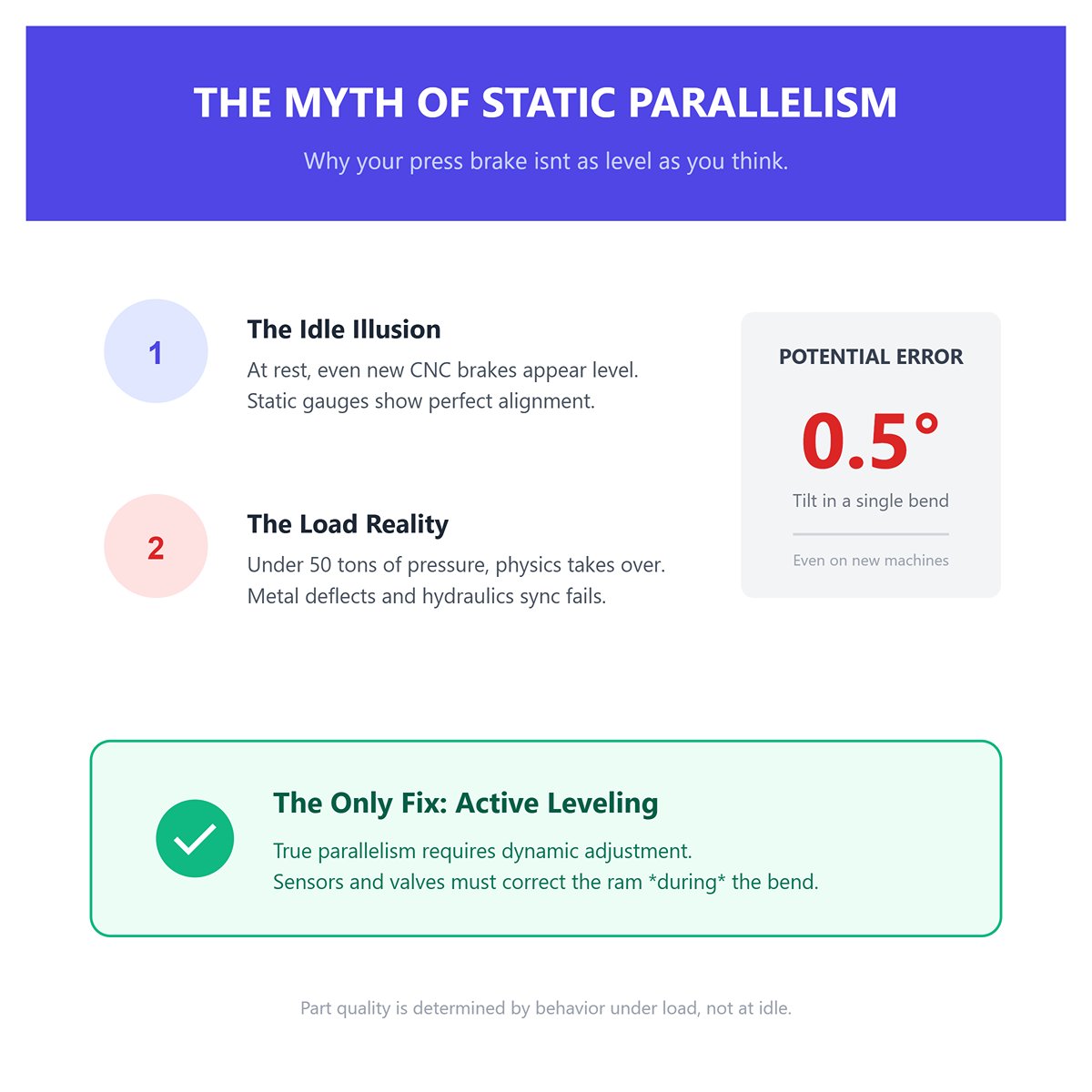
In press brake terms, “parallel” is about behavior under load—not no-load readings. At rest, even the newest CNC brake will show the ram within a few hundredths of a millimeter of level with the bed. But once 50 tons crash into steel, especially off-center, physics instantly takes over. Uneven resistance collides with hydraulic drive, sending one end of the ram down faster than the other. In a single bend, tilt can top 0.5°, even on brand-new machines fresh from the factory.
Static gauges, shims, and flashlight inspections only reveal part of the picture. When the press is loaded, metal deflects, hydraulics respond out of sync, and tiny clearances in guides suddenly matter. Without active leveling—where sensors constantly watch each corner of the ram and valves adjust during the bend—true parallelism exists only when the machine is idle, not during the tonnage surges that determine part quality.
The “canoe effect” happens when both ends of a flange come out sharp, but the center dips downward like the hull of a boat. Operators often suspect worn tooling, yet a simple test can pinpoint the real cause. Secure a one-meter mild steel bar, position the punch dead center, and run at full tonnage. If the bend angle in the middle differs by more than 0.5° compared to the ends, your ram is tilting—bowing in the middle as one side meets resistance sooner than the other.
In most fabrication shops, roughly 73% of ram tilt stems from uneven loading during the bend—not from worn tooling. When a cluster of punches on one side engages the material first, that side experiences resistance sooner, briefly slowing its descent. The other side, with less material contact, continues downward, introducing a subtle twist. Over thousands of bends, this repeated imbalance stresses the structure, shortens die life, and gradually erodes quality consistency. Advanced active leveling systems tackle the problem head-on, sensing and compensating for corner position differences within milliseconds. By making micro-adjustments in real time, they can counteract the canoe effect mid-bend, no matter where the workpiece is positioned.

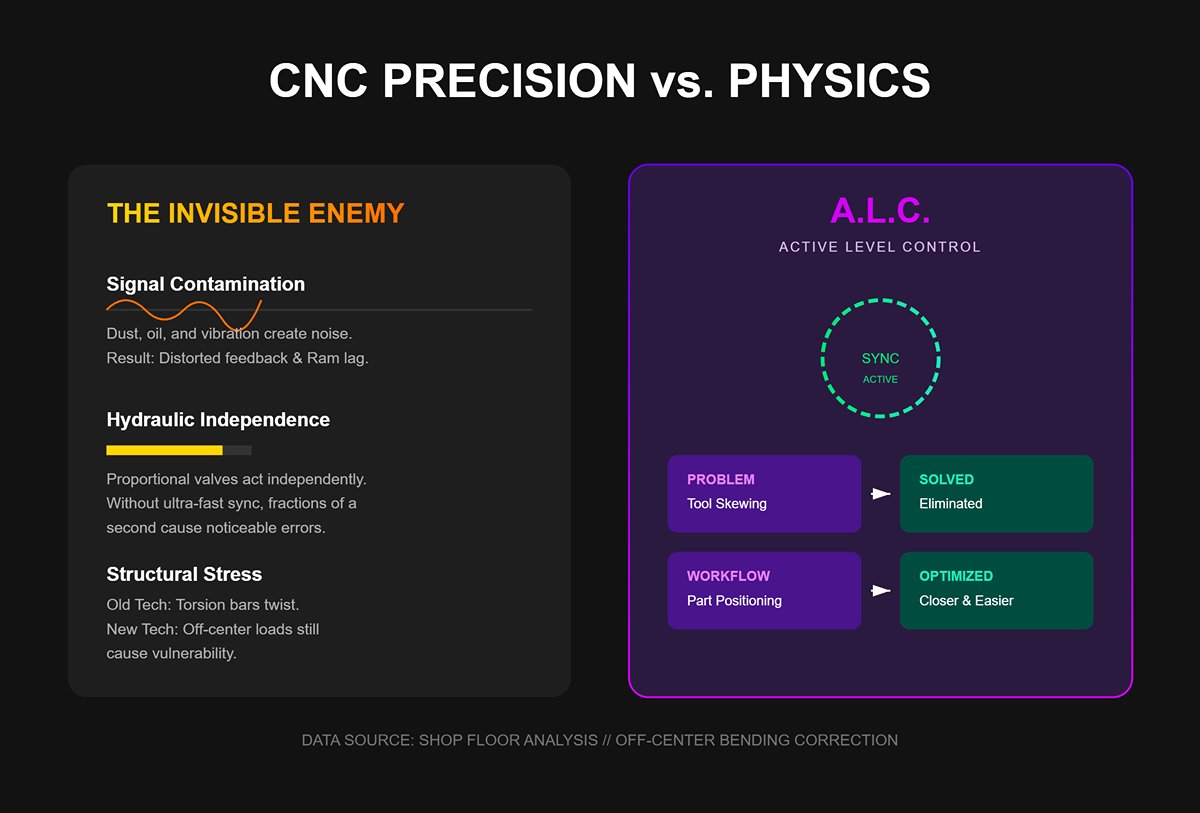
Even cutting-edge synchro-hydraulic CNC press brakes—equipped with dual linear scales (Y1/Y2) and self-centering capabilities—are still vulnerable to tilt. One reason is that encoder accuracy depends on pristine signal integrity. Contamination from dust, oil mist, or the subtle impact of vibration can distort signals, slightly slowing feedback and allowing one side of the ram to move ahead of the other. Hydraulic systems introduce their own delays as proportional valves operate independently; without an ultra-fast synchronization loop sampling thousands of times per second, those fractions of a second can generate noticeable bend inaccuracies under heavy loads.
Older machines make the issue more obvious, with torsion bars—intended to maintain parallelism—literally twisting under the strain of thick material. Yet even modern equipment becomes susceptible when bending off-center unless it’s equipped with smart compensation. Active Level Control (ALC), for example, instantly adjusts valve positions when staggered punches or unevenly placed parts cause imbalance. One shop running small dies across a wide bed found that this correction completely eliminated tool skewing, extended die service life, and allowed operators to position parts closer for easier handling—demonstrating that the laws of physics remain constant, and demand continuous management alongside advanced electronics.
Parallelism isn’t maintained by sensors and software alone. Worn or dry gibs—the sliding guides that keep the ram aligned—are responsible for nearly 40% of subtle tilt cases. Under full load, friction in a damaged or unlubricated gib can shift the ram just enough to cause cumulative errors over time. If the machine is even slightly out of level, the problem intensifies. Simple mechanical maintenance, such as re-setting eccentric nuts to restore uniform clearance, can cut scrap rates dramatically, often within a single shift.
Shimming is a common go-to for diagnosing parallelism issues and can accurately reveal micro-tilts when the machine is idle. However, under actual working loads, it often falls short. Paper compresses inconsistently when forming thicker materials, masking the true cause of deviation. While a flashlight can help you spot bed-to-ram gaps before bending begins, performing a controlled three-point air bend under full load offers a far more reliable assessment. This method captures deflection without subjecting tooling to unnecessary wear.
The key takeaway: parallelism matters most at the critical moment—when steel, tooling, and full tonnage come together. If the geometry at that instant is compromised, you’ll see warped parts, rising scrap rates, and an endless circle of blame. To break this cycle, define “parallel” in terms of loaded performance, verify tilt with controlled testing, and respect the physical realities of both new and well-worn brakes. That’s how you stop scrap from creeping higher—and put an end to the finger-pointing.
Even without high-end measurement tools, you can quickly determine whether a press brake’s ram is aligned across its length. With the machine powered down and all tooling removed, lower the ram until it’s just above the bed. Shine a bright flashlight along the contact line between the ram and the bed, starting from one end. Any irregularities in the shadow or visible gaps signal uneven contact. For best results, work in a dimly lit environment—this makes subtle light variations easier to detect.
If you have basic shop tools, you can turn this into a more exact measurement using a magnetic-base dial indicator with 0.01 mm precision. Zero the indicator beneath one end of the ram, then move it carefully toward the opposite end in small increments. A deviation beyond ±0.01 mm per meter suggests the ram is no longer parallel, which will likely produce uneven bending forces. To confirm, many operators slide a strip of white paper or thin aluminum foil between punch and die—an even mark along the full length is the sign of correct alignment.
This step’s value lies in its speed and clarity—it sets a baseline before you adjust crowning or cylinder synchronization. If this initial line check shows misalignment, no amount of crowning will deliver uniform bends.
Parallelism problems aren’t always about glaring misalignment—often, they stem from minuscule tilts that only reveal themselves when the ram reaches bottom dead center under full load. The shim paper test is designed to pinpoint these. Place narrow strips of uniform-thickness paper (or, for greater precision, feeler gauges) between the punch and die at three locations: left, center, and right. Slowly cycle the ram down to bottom dead center, then note which strip grips first and how firmly. For example, if the right-hand strip pulls away with less resistance, that side is fractionally higher and delivering reduced forming pressure.
Paper is ideal for this test because it offers clear tactile feedback without damaging the tooling, and the uniform drag makes variations easy to detect. In pronounced tilt situations, one side may release the paper cleanly while the other crimps it sharply—a clear sign that the hydraulic cylinders aren’t synchronizing when under load.
This method exposes subtle tilts capable of producing angle variations of a degree or more—particularly problematic with thin stock, where the margin for forming pressure is very tight. Results like these point directly to issues with cylinder calibration or bed shimming, neither of which can be fixed by simply adjusting offsets.
Bed deflection and ram misalignment can cause similar bending errors, yet they require different corrective actions. The 3-point air bend test helps distinguish between them. Fit a clean, straight punch and die suitable for a mild steel sample, then air bend a long workpiece. Immediately measure the resulting bend angle at three points: the left end, the center, and the right end.
If both ends show identical angles but the center is more open (less bend), the cause is bed deflection—your bed is bowing under load, and crowning or bed support adjustments will be needed. If instead one end is consistently tighter than the other, the problem is a parallelism error in the ram’s travel. A difference greater than 1° between ends is a serious warning in most production settings; running without correcting it invites escalating scrap rates and rework.
Because this test applies real forming forces, it reveals the press brake’s true performance under working conditions—sidestepping the deceptive comfort of unloaded measurements. It also shows whether modern CNC crowning compensation is actually delivering the angles reported by the controller, or if the machine’s feedback loop is drifting out of spec.
When operators spot inconsistencies in bend angles, their first instinct is often to tweak crowning settings or insert shims. Yet, the smarter—and often overlooked—approach is to begin with three focused diagnostics in succession, before touching either mechanical or software controls. Whether you’re working with a classic 1980s mechanical press brake or a state-of-the-art CNC model featuring Y1/Y2 cylinder control, these quick tests can pinpoint the real culprit far more effectively than making blind adjustments.
A simple flashlight line check reveals major misalignment in moments; the shim-paper test detects subtle tilts under load; and the three-point air bend distinguishes between overall deflection and true tilt. Together, these methods deliver a complete mechanical diagnosis, empowering you to tune hydraulics, crowning, or tooling with precision and confidence—no guessing required. This disciplined process not only shortens setup times but also cuts waste by ensuring every correction targets the genuine source of error.
In modern press brakes, the Y1 and Y2 axes—each representing one end of the ram—are continuously monitored by ultra-precise linear encoders, often glass scales mounted vertically inside protective casings. These encoders feed the CNC controller a stream of live positional data thousands of times per second, enabling it to keep the ram perfectly parallel during forming. However, airborne contaminants such as oil mist, fine grinding dust, and other particulates can settle as a light film across the optical strip. Once fouled, the encoder may misread the light pulses from its sensor, subtly corrupting the position signals it sends to the controller.
The hazard is easy to miss but can be costly: the CNC might register both ends as level when, in reality, one side is 0.02 mm lower. On parts exceeding two meters in length, that minor tilt shows up as a visibly uneven bend angle. Surveys indicate that contamination is responsible for about 70% of stubborn parallelism issues. Just one dusty production shift can throw a press brake out of tolerance—one manufacturer saw $8,000 in scrap before tracing the problem back to dirty encoders.
The solution can seem counterintuitive. Because modern CNC systems adjust in real time at extremely high speeds, operators often believe that contamination can’t overpower the machine’s ability to self-correct. In practice, dirt or residue can weaken the encoder’s optical signal enough to obscure true ram movement—effectively breaking the feedback loop. A simple diagnostic: move the ram to top dead center, compare the live position readings for Y1 and Y2, and look for any difference greater than 0.015 mm. If you see this, clean the encoder’s optical scales using lint-free wipes and isopropyl alcohol, then perform a complete homing cycle to establish a new zero point. Those ten minutes of maintenance can take bend angle variation from over a degree down to nearly zero.
Press brakes don’t all control Y1 and Y2 in the same way. Torsion bar machines use a solid mechanical shaft to keep the ram ends aligned. The bar twists when load is offset, sharing the force along its length. Push the load too far—for instance, by exceeding the machine’s tons-per-inch limit on one end—and the bar can be permanently distorted, causing every future bend to be slightly off-level. Over time, wear in the torsion bar’s eccentric or gib interface, especially beyond 0.008 inches of clearance, will make the problem worse after tens of thousands of cycles.
Synchro-hydraulic models swap the mechanical linkage for two independent hydraulic cylinders, each controlled by proportional valves. While each side operates independently, constant encoder signals keep them in step. These machines can actively correct ram tilt as it happens—until one cylinder begins falling behind. That lag can be caused by pressure imbalances, internal oil leakage, or air pockets compressing unevenly under load. When this happens, the resulting issue shows up as subtle but consistent changes to the bend angle pattern.
Pinpointing which type of system you’re dealing with is crucial, as the fixes differ. For torsion bar setups, lasting correction may require physical work—such as adjusting gibs with shims, machining the bar to restore precision, or replacing the linkage outright. Synchro-hydraulic troubleshooting, on the other hand, often involves isolating cylinders for testing, or fine-tuning valve settings according to factory specifications. A quick field check: perform an air bend at each end of the machine. If the left produces noticeably shorter legs than the right, hydraulic synchronization is likely the culprit.
| Feature | Torsion Bar System | Synchro-Hydraulic System |
|---|---|---|
| Control Method | Uses a solid mechanical shaft to keep ram ends aligned; bar twists to share force along its length. | Uses two independent hydraulic cylinders controlled by proportional valves and synchronized via encoder signals. |
| Response to Load Offset | Shares force mechanically; excessive offset can permanently distort the bar. | Actively corrects ram tilt until one cylinder lags due to various issues. |
| Common Issues | Permanent distortion from exceeding tons-per-inch limit; wear in eccentric/gib beyond 0.008″ clearance. | Cylinder lag from pressure imbalances, internal oil leakage, or air pockets. |
| Long-Term Effects | Distortion causes every future bend to be slightly off-level; wear worsens with tens of thousands of cycles. | Lag leads to subtle but consistent changes in bend angle pattern. |
| Typical Fixes | Adjust gibs with shims, machine the bar, or replace linkage. | Isolate cylinders for testing; fine-tune valve settings per factory specs. |
| Quick Field Check | Not specified. | Air bend at each end—shorter legs on one side indicates hydraulic synchronization issue. |
In synchro-hydraulic setups, repeated off-center bending creates uneven pressure between cylinders. Over time, one cylinder ends up working harder—say, at 3,000 psi compared to the other’s 2,500 psi—and its internal seals wear out more quickly. Once a seal begins to fail, hydraulic oil can bypass inside the cylinder, letting the ram drift when the machine is powered down overnight. The result is a visible sag on one side, and you’ll start seeing inconsistent angles along the workpiece well before the seal completely gives out.
By the second or third year of use, uneven seal wear becomes fairly common—field data shows that about 60% of affected presses experience noticeable drift. Off-center loading speeds this up by concentrating stress on one side, and worn gibs make matters worse, leading to what operators call “canoe effect” bends—long, concave or convex shapes in thick material. One shop traced unstable 5 mm steel flanges to just 0.006 inches of drift and cut downtime costs sharply by replacing the seals and bleeding the hydraulics, bringing cylinder pressures back into balance.
Watch for early hydraulic warning signs: a pause when shifting from rapid descent to slow bending, or a faint vibration as the ram returns. These can be subtle indicators of imbalance. Placing support blocks under the ram after shutdown can hold any visible drift in place, helping you catch the issue before it grows into a serious production problem.
Whether the cause is optical, mechanical, or hydraulic, most parallelism problems boil down to one fact: Y1 and Y2 must move in perfect sync. Under load, that means staying within 0.01 mm; anything beyond that risks introducing tilt, uneven angles, and higher scrap rates. A study of 200 workshops showed that simply re-synchronizing the Y-axis drives reduced scrap by 25% within a single day.
The “ghost” isn’t usually a warped frame—despite popular belief, frame distortion is responsible for only a small fraction of cases. More often, it’s a feedback failure. If one side sends inaccurate readings, responds sluggishly, or floats in worn guides, the CNC’s closed-loop control loses precision. Running live diagnostics and performing immediate maintenance keeps the system reliable.
| Symptom | Likely Y1/Y2 Cause | 5‑Minute Remedy |
|---|---|---|
| Left side bends shorter | Dirty Y1 encoder | Clean lens, reset reference |
| Right side delay/tilt | Y2 cylinder leak | Check for drift when powered off, bleed air |
| Both sides wavy on thick plate | Gib clearance over 0.008″ | Re-shim guide rails |
| Hesitation at slowdown | Valve synchronization issue | Run parallelism test |
Bottom line: pinpoint the feedback fault, fix it quickly, and bring the Y-axis back into precise sync. Do that, and the elusive “ghost” distorting your bends vanishes—along with a substantial chunk of your scrap output.
A press brake ram can measure perfectly parallel to the bed when idle, yet still yield noticeably arched components under working load. This stems from unavoidable deflection—the flexing apart of the ram and bed under force—which becomes most apparent in machines with beds longer than three meters. When bending thick plate or broad sections, the center of the bed, lacking end support, separates more than the edges, producing the familiar “canoe effect.”
In real-world terms, this shows up as excessive bend in the middle of a workpiece while the ends remain under-bent, a pattern often mistaken for ram tilt or Y-axis mismatch. Knowing the difference is essential: if deflection is the true cause, adjusting for parallelism in a stationary state will not correct forming accuracy. A shop may record a flawless 0.00° end-to-end in static tests, yet still produce parts with a half-degree gap between center and ends once the press is engaged.
True ram tilt presents differently: one side of the brake consistently hits a steeper or shallower angle during the bending cycle. This lateral variation often comes from unsynchronized Y1/Y2 cylinder motion, worn gibs, or a hydraulic leak affecting one end of the ram. You can spot tilt by checking bend angles at matching positions on each end and noting persistent imbalance.
Bed deflection, on the other hand, is a vertical bending of the machine’s length. Crowning systems—whether mechanical wedges or hydraulic setups—are designed to counteract this by slightly arching the bed upward before the stroke. Advanced hydraulic crowning uses independently controlled cylinders to make on-the-fly adjustments, offsetting mid-span sag of 0.1° to 0.5° during long, heavy-duty bends.
The core diagnostic step is to apply a controlled load at the center of the machine using a short test bar, then repeat the process at each end. If the center produces bends that exceed those at the ends by more than roughly 0.5°, the crowning system isn’t providing adequate compensation. Trying to “square” the ram without resolving crowning issues wastes effort and can accelerate wear in other components. On the other hand, if one side consistently produces shallower bends regardless of where the load is applied, suspect a tilt problem and inspect the gibs, cylinder synchronization, and valve responsiveness.
Relying solely on a midpoint check for ram parallelism may be a convenient shortcut, but it misses two of the most revealing signs of trouble: a gradual taper along the machine’s length, and temporary tilt during changes in stroke speed. Wear in the gibs or drifting Y-axis synchronization usually appears most clearly at the outer stations rather than in the middle.
Operators who concentrate only on the central area may overlook overnight ram drift caused by internal seal bypass—when hydraulic fluid slips past worn piston seals. This can show up as uneven or sluggish ram return, slight shuddering when the stroke reverses, and small but measurable bend variations toward one end after idle periods. If the ram drops by more than 0.02 mm during shutdown, the issue is tilt rather than crowning.
Field evidence offers a warning: gib clearances wider than 0.15 mm twice the risk of tooling fractures due to concentrated loading. In these cases, adjusting crowning only conceals the underlying issue; the uneven load distribution continues to wear out tooling and create irregular bends. The only trustworthy method for distinguishing between tilt and deflection is to measure from end to end under actual forming loads. On CNC machines, frequent Y-axis homing helps realign encoders and restore synchronization precision; for mechanical presses, make balanced eccentric nut adjustments in very small increments.
Don’t assume that perfect alignment at rest ensures high-quality results when under load. Instead of beginning with a static parallelism check, place a representative test piece in the brake and make bends at the center and each end, recording the angles immediately. If the variation grows toward the middle under identical conditions, you’re dealing with deflection; if the difference stays consistent in one direction along the bed, the problem is tilt.
Reordering the test sequence in this way greatly reduces the likelihood of misdiagnosis. Field data from Accurl indicate that shops implementing a load-first diagnostic approach cut adjustment time in half and minimize scrap on long-channel projects by pinpointing crowning problems early on. Where possible, enable dynamic crowning compensation within the CNC control, and check gib clearances along with Y-axis synchronization before making any changes to wedges or shims. These measures ensure that “parallelism” reflects the press brake’s performance under the only conditions that truly matter—actual forming load.
It’s common for operators to mistake ram tilt on a CNC press brake for a hydraulic or mechanical failure, when in reality it’s often caused by a far simpler problem: logic drift. Interruptions in power supply, contamination on optical scales, or even ambient vibrations can cause the Y1 and Y2 axis encoders to fall out of sync. This deviation—sometimes as little as 0.02 mm—can produce a tapered bend that looks identical to a genuine mechanical tilt.
Running a forced homing cycle recalibrates the machine’s internal axis references, bringing both sides back into precise alignment without making any physical adjustments. To do this, move the ram to top dead center (TDC) and enter service mode—on most Cybelec and Delem controllers, select “Reference All Axes.” Complete the re-referencing, then clean the linear scales with a lint-free cloth and isopropyl alcohol to remove dust or grease that may block the optical sensors. Many shops report that roughly 70% of tilt issues on newer press brakes disappear after this process, with scrap rates dropping immediately and no mechanical intervention required.
If homing restores accuracy but tilt returns within a few days, inspect cylinder synchronization in diagnostic mode. A time lag of more than 50 ms between cylinders often signals trapped air; bleeding the hydraulic system before running high-tonnage jobs will prevent these repeat, false-tilt incidents.
In older mechanical press brakes, ram alignment is managed not by servo-controlled axes but by manually adjustable hard stops—eccentric nuts positioned at each end of the crankshaft. Adjusting the eccentric allows fine-tuning of the ram’s bottom dead center relative to the bed, correcting parallelism problems caused by worn gibs or uneven frame distortion.
Begin by loosening the locknut and rotating the eccentric in fine steps—typically 0.002 to 0.005 in per side. Use a dead-blow hammer to prevent shock-loading the shafts, and verify each change via dial indicators mounted at both ends of the ram. Follow the guiding principle: “small, frequent, symmetrical” adjustments. Matching movements on both sides prevents you from swapping one type of twist for another. One fabricator successfully eliminated severe canoe-shaped bends in 5 mm mild steel simply by re-squaring a ram with a 0.15 mm gib gap, without making any other modifications.
Avoid the temptation to overcorrect. Excessive adjustments can push the gibs beyond their design tolerance, creating extra clearance that accelerates wear and significantly increases the risk of a catastrophic guide fracture.
Every gib—whether fitted with bronze wear strips or rolling bearings—has a maximum allowable clearance. Once exceeded, the ram stops gliding smoothly, and bending impact loads concentrate on single points. Field data indicate that when ram-to-gib clearance surpasses 0.008 in (0.20 mm) for mid-length machines, fractures often occur within just a few hundred normal-tonnage cycles.
A practical upper limit for adjustment is a total taper of 0.006 in across the ram—roughly 0.003 in per side. Beyond this, any improvement in parallelism is outweighed by mechanical risk. The permissible limits are slightly higher for longer rams, but they remain finite:
| Ram Length | Max Gib Clearance | Taper Limit Before Gib Failure Risk |
|---|---|---|
| <3 m | 0.006 in (0.15 mm) | 0.003 in per side |
| 3–6 m | 0.008 in (0.20 mm) | 0.004 in per side |
| >6 m | 0.010 in (0.25 mm) | 0.005 in per side |
To measure these values, use feeler gauges at top dead center. On hydraulic brakes, support the ram with blocks if internal seals are likely to bleed down overnight. Ignoring clearance limits can be costly—gib fractures on mid-capacity brakes can lead to more than $5,000 in rebuild expenses plus weeks of lost production.
Many parallelism corrections fail not because the adjustments were ineffective, but because the actual problem wasn’t mechanical in the first place. On modern CNC machines, minor sensor drift causing axis desynchronization is responsible for over half of reported tilt issues. Operators often jump straight to shims, wedges, or hard-stop changes, inadvertently introducing wear that didn’t exist before.
Initiating a forced homing cycle tackles the most common root cause with minimal risk. If, after re-referencing and applying full working load, the tilt still persists, only then should you proceed to mechanical adjustments—and strictly within the taper tolerances outlined above. Following this step-by-step method avoids turning a minor issue into a costly failure, preserves gib integrity, and can replace an expensive service visit with a quick reset. In press brake work, precision compounds over time; safeguarding that precision begins with correctly matching the reset method to the specific fault.
Inserting shims beneath a tilted ram is often promoted as a fast fix when bend angles begin to drift—but under operational loads, it’s inherently unreliable. On a hydraulic press brake, even a slight ram tilt shifts tonnage distribution unevenly between the cylinders. If one cylinder already suffers internal leakage—a common occurrence past 5,000 operating hours—the minor height offset intensifies under pressure. Operators will often slide in a sliver of shim stock, typically ranging from 0.005″ to 0.020″, at the die seat or gib to “level” the ram. Under full tonnage, that thin insert yields instantly, turning the intended correction into a new source of tilt.
Loss of hydraulic synchronization is most acute during the shift from rapid approach to forming speed. At this point, the dynamic load on the shimmed side can surge 20–30% above normal, crushing the shim and causing a mid-cycle change in bend angle—often about 0.5° across the workpiece. On longer parts, particularly three-meter sections, that variance can climb to 1–2°, enough to send precision components straight to the reject bin. One recorded case saw a shop shimming a 150‑ton Amada increase its scrap rate by 15% within a week; inspection revealed dead-bottom gap fluctuations ranging from 0.02 mm to 0.18 mm in just one stroke.
The risk is amplified by deceptive idle checks. Air pockets in hydraulic lines can make a shimmed arrangement feel stable during slow jog testing, concealing the problem until production speeds crush the shim and distort bends. By then, the underlying hydraulic or synchronization fault remains uncorrected, and workpiece geometry damage is already in progress.
Placing a shim on just one side of the ram doesn’t merely shift its position—it acts like a lever against the machine frame. This lever effect creates point loading, where force is concentrated in a narrow section rather than distributed evenly along the bed. In real-world use, it’s common to see up to 60% of the tonnage concentrated within just 12–18 inches, surpassing the yield strength of gib steel (about 150 ksi) by roughly 40%. The result: one side of the ram effectively “floats,” while the other side’s guideways are forced to absorb excessive torque.
When gib clearance exceeds 0.006″ (0.15 mm), some degree of float and rebound is already possible. Adding an off-center shim transforms that minor clearance into a significant stress amplifier. Seal bypass in the slower cylinder deprives one end of the ram of adequate pressure, leaving the opposite, overloaded end wedged in its guides. This imbalance generates torsional forces that initiate microfractures in tooling—especially around punch shoulders. In documented cases, cracks penetrated 2–3 mm deep after only 200 bending operations, despite the machines showing no other mechanical defects.
The problem intensifies in synchro-hydraulic press brakes where valve response delays reach about 50 ms. For example, on a 4-meter Durma, shimming the right side led to guideway binding, which snapped a $2,500 punch radius overnight. Even very thin shims—less than 0.010″—can gouge into the bed rails, leaving scored depressions. These indentations capture metal debris, dramatically accelerating abrasive rail wear by four to five times compared to the gradual drift caused by normal hydraulic variance.
Using shims to correct a tilted ram puts the frame under a constant imbalance it was never engineered to bear indefinitely. Over prolonged use, one side deflects as much as 1.5 times more than the other. This imbalance leaves a residual bow in the ram—typically 0.5–1 mm for every ton above its rated capacity—and once the beam’s yield limit is exceeded, the deformation becomes permanent. Restoring proper geometry then demands expensive remachining or, in severe cases, complete ram replacement.
Bed rails take the hit just as hard. When extra tonnage is concentrated on the shimmed side, localized wear can deepen by as much as 0.003″ per month in high-demand setups. Machines that should run five years before rail re-machining can burn through that margin in as little as 18 months, racking up repair costs anywhere from $15,000 to $30,000. The hydraulic seals on the overworked side also fail nearly twice as often, often spilling a quart or two of fluid weekly. That constant loss causes subtle ram drift—around 0.02 mm per shift even while idle—quietly eroding angle consistency before the next job ever begins.
Attempting to sidestep the issue is a costly illusion: some operators prop blocks under the ram overnight to “hold” alignment, but that only conceals the underlying damage. After shimming, assemblies often require eccentric nut resynchronization, yet nearly half of these presses suffer torsion bar fatigue within a year—a breakdown that can run $8,000 once lost production is tallied. From a purely financial perspective, re-homing encoders and bleeding hydraulic lines before resorting to shims isn’t just safer—it’s the smarter investment.
Most repair manuals treat shimming as a harmless stopgap until professional servicing is available. In practice, it’s more like introducing deliberate mechanical stress disguised as a maintenance shortcut. What presents itself as a quick leveling fix in fact wedges apart the press brake’s design tolerances with every ram cycle. Once cumulative distortion settles in, the deterioration speeds up—tooling failures multiply, wear surfaces degrade more rapidly, and control adjustments simply hide the physical breakdown. The real path forward after spotting ram tilt is to correct synchronization and hydraulic feed problems directly. Shimming a tilted ram doesn’t buy you time—it sells off future precision at a steep cost.
Every misaligned bend you’ve been chasing starts sooner than you realize—well before metal meets the tooling. It begins the moment parallelism starts to drift silently, hidden in extra gib clearance, timing lag, or an unseen seal bypass. By Friday evening, that imperceptible shift is already setting the size of Monday’s scrap pile.
Parallelism isn’t just a calibration option—it’s a physical condition you either confirm or lose. The key isn’t an on-the-fly tweak mid-production; it’s securing precision before the next cycle has the chance to shake it loose.
Step 1: Reset Your View and Your Encoders. Move both Y1 and Y2 axes to top dead center, then zero the encoder scales. Any deviation beyond 0.02 mm is a defect worth addressing right now—not after the weekend. If the sensor optics are dirty, clean them with isopropyl alcohol before drift turns into measurable angular error.
Step 2: Check Your Clearances. Use a flashlight to inspect each gib rail. If clearance exceeds 0.008″, the ram can shift under load. That subtle movement is tilt in slow motion, often translating into 20–30% more scrap on longer workpieces. Shim or resurface before the next production run.
Step 3: Hold, Measure, Decide. Apply a 50% tonnage hold at the left end, right end, and center for 30 seconds. Place a straightedge across the punch tips—if one side lowers more than 0.5°, you’re dealing with a synchronization fault. Letting it go until Monday will guarantee uneven angles across the sheet.
Step 4: Let the System Breathe. Run the hydraulics through five complete strokes. Listen—not for loud noises, but for consistent rhythm. A jerky return signals trapped air or uneven pressure, both of which will cause angle drift precisely when the machine transitions from fast approach to slow forming.
Shops using CNC machines with live tilt monitoring have a clear advantage—before wrapping up, enable auto-correction in the setup menu. Modern control systems can adjust proportional valves thousands of times per second, reducing heavy-stock errors by up to 90% without the need for operator action.
Ignore overload alerts and you’re not just bending metal—you’re permanently distorting the ram. Exceeding the tons-per-inch limit by 20% crowns the bed and turns your budget into a $10k-plus rebuild bill. Follow air-bending limits; use center-loading only when the job truly calls for it.
One fabricator cut angle variation from 1.2° down to 0.1° in just one afternoon—not through exhaustive maintenance, but by pinpointing cylinder lag during the slowdown phase, tweaking a single valve, and locking in stability before the weekend. That’s the sweet spot: fix issues before downtime so Monday starts perfectly on spec.
Five minutes spent on Friday calibration is your insurance against guesswork. Because when Monday rolls around, the goal isn’t to find tilt—it’s to be stacking finished parts.


