

I watched a 10-foot length of 1/4″ A36 go from a comfortable 139 tons to a screaming 300 tons just by swapping a 3-inch V-die for a 1.5-inch one. Same material. Same thickness. Same operator. The only thing that changed was die opening.
That swing alone is 115%.
And you’re still trusting a pocket formula that pretends one constant fits all.
Most shops keep some version of this on the wall:
P = 0.012 × t² × Fy / W
Where t is thickness, Fy is material strength, and W is die opening.
Looks clean. Looks universal. It isn’t.
That 0.012 constant was born in a world of 60,000 psi mild steel, air bending, and the old 8× thickness die rule. Change one variable—switch to stainless at 90,000 psi tensile, or aluminum at half that—and the multiplier hiding inside Fy quietly shifts your tonnage by 50% in either direction. Stainless doesn’t “act like steel but harder.” It multiplies force demand. Aluminum doesn’t forgive bad math. It just wrinkles differently.
Now stack that with unit sloppiness. I’ve seen shops mix short tons (2,000 lb) with metric tonnes (2,204 lb) and N/mm² without converting. That alone can skew force 8–10% before you even touch material differences. You think the formula failed. It didn’t. You fed it garbage.
So where exactly does that 0.012 come from, and why does it behave like loaded dice?
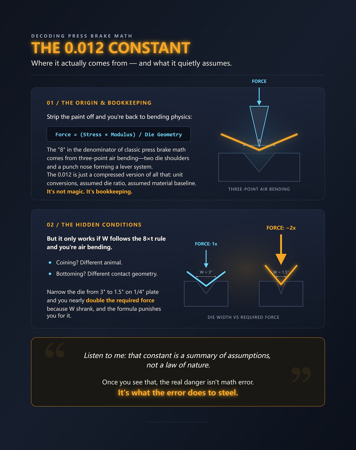
Strip the paint off and you’re back to bending physics: force equals bending stress times section modulus, divided by die geometry. The “8” in the denominator of classic press brake math comes from three-point air bending—two die shoulders and a punch nose forming a lever system.
The 0.012 is just a compressed version of all that: unit conversions, assumed die ratio, assumed material baseline, assumed air bend. It’s not magic. It’s bookkeeping.
But it only works if W follows the 8×t rule and you’re air bending. Coining? Different animal. Bottoming? Different contact geometry. Narrow the die from 3″ to 1.5″ on 1/4″ plate and you nearly double the required force because W shrank, and the formula punishes you for it.
Listen to me: that constant is a summary of assumptions, not a law of nature.
Once you see that, the real danger isn’t math error. It’s what the error does to steel.
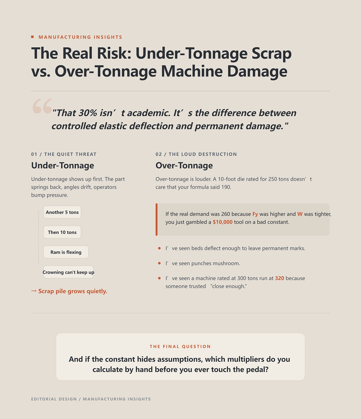
Under-tonnage shows up first. The part springs back, angles drift, operators bump pressure. Another 5 tons. Then 10. Now the ram is flexing and your crowning can’t keep up. Scrap pile grows quietly.
Over-tonnage is louder.
A 10-foot die rated for 250 tons doesn’t care that your formula said 190. If the real demand was 260 because Fy was higher and W was tighter, you just gambled a $10,000 tool on a bad constant. I’ve seen beds deflect enough to leave permanent marks. I’ve seen punches mushroom. I’ve seen a machine rated at 300 tons run at 320 because someone trusted “close enough.”
That 30% isn’t academic. It’s the difference between controlled elastic deflection and permanent damage.
And if the constant hides assumptions, the next question is simple: which multipliers do you calculate by hand before you ever touch the pedal?
I watched a 90‑ton air bend turn into a 260‑plus‑ton bottoming job without changing the part print.
Same 1/4″ A36. Same 8×t V‑die. Same punch radius. The only thing that changed was how deep the operator drove the ram. First pass: clean air bend at 90°, pressure peaked around 92 tons across 10 feet. Second pass: he chased springback by burying the punch until the legs contacted the die faces. The gauge climbed past 240 before I told him to get his foot off it.
That swing didn’t come from thickness. It didn’t come from tensile strength. It came from bending method.
You’re asking which multipliers you calculate by hand before committing to a tonnage number. Here they are: material tensile strength factor, die opening ratio, and bending method coefficient. The last one is the one most shops pretend doesn’t exist. They treat air bending, bottoming, and coining like they’re the same physics with different pedal pressure.
They’re not.
Listen to me: changing bending method is not “fine-tuning.” It rewrites the force distribution inside the V‑die, and that’s how a safe setup becomes a $10,000 die repair.
So what actually changes inside that V?
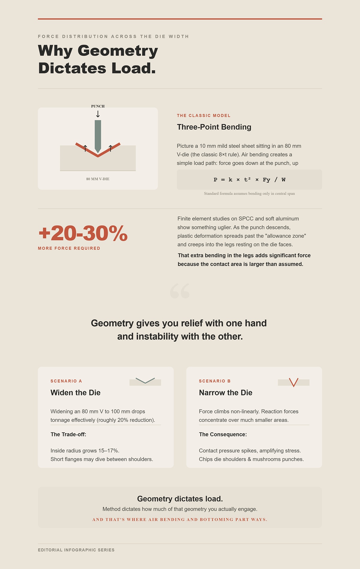
Picture a 10 mm mild steel sheet sitting in an 80 mm V‑die. Classic 8×t rule. You air bend it. The punch contacts at the center. The sheet touches the die at two shoulders. Three-point bending. The load path is simple: down at the punch, up at two shoulders, bending moment in the middle.
The standard formula P = k × t² × Fy / W pretends the sheet only bends in that central span.
Finite element studies on SPCC and soft aluminum show something uglier. As the punch descends, plastic deformation spreads past the “allowance zone” and creeps into the legs resting on the die faces. That extra bending in the legs can add 20–30% more force than the clean textbook model predicts. Not because the math is wrong, but because the contact area is larger than assumed.
Now widen that 80 mm V to 100 mm for the same 10 mm sheet. Shops do this to drop tonnage. And it works — roughly a 20% reduction in required force. But the inside radius grows 15–17%, and if the flange length is shorter than the die span, the part dives between the shoulders. Geometry gives you relief with one hand and instability with the other.
Narrow the die instead and the force doesn’t just climb linearly as W shrinks. Contact pressure spikes because the reaction forces concentrate over smaller areas. Stress is force divided by area. Shrink the area and you amplify stress. That’s how you chip die shoulders and mushroom punch noses while the tonnage gauge still looks “within range.”
Geometry dictates load. Method dictates how much of that geometry you actually engage.
And that’s where air bending and bottoming part ways.
Air bending stops before the sheet fully seats into the V. The punch sets the angle by depth, not by forcing the material to conform to the die angle. Springback is expected. Force rises smoothly, peaks, and you’re done.
Bottoming keeps going.
In bottoming, the sheet is driven until its legs contact the die faces firmly. You are no longer just creating a bending moment in mid-span. You are forcing the entire inside surface to match the die angle. Contact area increases. Friction increases. Plastic strain increases in the legs.
On the same die, same material, same thickness, bottoming commonly requires 2–3× the tonnage of air bending. Not because someone changed the formula, but because the boundary conditions changed. The sheet is no longer a beam on three points. It becomes a wedge being pressed into a cavity.
Take that earlier 90‑ton air bend. Multiply by 2.5 and you’re at 225 tons. Add 20% because the actual tensile strength of your “mild” steel batch runs higher than book value, and now you’re brushing 270 tons. Your brake is rated at 250 across that length. Your die is stamped 240 max.
You just turned a comfortable job into a red‑zone load case by pushing 6 mm deeper.
And here’s the part operators forget: in P = k × t² × Fy / W they remember thickness. They argue about Fy. They completely ignore that W only governs force the way the formula predicts under air bending assumptions. Switch method, and the effective multiplier on the whole equation changes.
But bottoming still isn’t the ceiling.
I’ve seen a young operator try to “clean up” a radius by cranking pressure until the inside corner looked sharp.
That wasn’t bending anymore. That was coining.
Coining drives the punch tip into the material with enough force to exceed yield through the full thickness at the bend line. You’re not just forming curvature. You are plastically compressing the inside fibers and ironing the radius to match the punch nose.
The force requirement jumps again — often 5× air bending tonnage for the same thickness. Why? Because now the required stress approaches the material’s compressive strength across a contact area defined by the punch tip radius, not the die span. Tiny area. Massive pressure.
Stress = Force / Area.
Cut the contact area to a narrow punch tip and the force required to reach yield skyrockets. The machine doesn’t care whether you call it “just a little more pressure.” It only knows you’re asking a 300‑ton frame to behave like a forging press.
That’s how beds take a permanent set. That’s how punches crack at the tang. That’s how you scrap a hardened die set worth $10,000 because the tonnage chart on the wall didn’t have a column labeled “operator ego.”
So before you ever step on the pedal, you calculate:
Because once you understand how force spreads — or concentrates — inside the V‑die, the formula stops being a magic constant and becomes a controlled calculation.
And if the method can triple your tonnage without changing the print, how exactly do you rebuild the calculation step by step so the next 90‑ton job stays 90 tons?
A 10‑gauge sheet, 10 feet long, sitting on the bed. The chart on the wall says 8.4 tons per foot in air bending with a 1.125″ V. That’s 84 tons. Clean. Comfortable.
Now the operator swaps to bottoming to “tighten the angle,” and the load quietly climbs past 200 tons. Same material. Same thickness. Same die set. Only the method changed.
You don’t fix that with a better chart. You fix it with a calculation that forces you to account for every multiplier — units, UTS, die opening, and bending method — in the right order. This is how you keep a 90‑ton plan from becoming a 270‑ton repair bill.
Let’s build it the way you’d build a die set: square, aligned, and verified at every face.
I once watched a junior engineer punch numbers into F = (k × L × t²) / V
Thickness in millimeters. Die width in inches. Length in feet. The brake groaned like it was being asked to cold forge a crankshaft.
25.4 millimeters in an inch. Miss that conversion and you don’t get a 5% error. You get a 25.4× distortion baked into the geometry term. And because thickness is squared, the mistake compounds inside t² before it ever reaches the denominator.
Listen to me: pick one system — all inches and tons, or all millimeters and kilonewtons — and convert everything before you touch the formula.
If you’re working in metric, the common air-bend form is: P = 650 × t² × L / V
Where:
That 650 constant quietly assumes mild steel around 450 N/mm² tensile strength and air bending conditions. It is not universal. It is conditional.
Get the units wrong and you won’t know whether your 20% safety margin just became a 200% overload. And if the foundation is crooked, what happens when we start adjusting for real material strength?
Pull a mill cert on “mild steel” and you’ll see tensile strengths ranging from 400 to over 550 N/mm² depending on grade and heat. The standard constant assumes about 450 N/mm².
That’s a 22% swing hiding inside a word: steel.
The force scales directly with tensile strength. If your sheet’s UTS is 540 N/mm² and your baseline constant assumed 450, your correction factor is:
Actual force = Calculated force × ( UTS_actual / UTS_baseline ) = F_calc × (540 / 450) = F_calc × 1.2
That 84‑ton air bend just became 101 tons. No die change. No method change. Just honest material data.
Switch materials and the swing gets uglier. Aluminum might need roughly half the force of mild steel. Austenitic stainless can push 1.5× or more depending on grade. Same thickness. Same die. A 3× range across common shop materials. And this variability doesn’t stop at bending—your cutting process has to manage the same spread in strength and reflectivity. High-power, CNC-controlled systems like the laser cutting machines from CN-HAWE are built to handle mixed-material production environments, helping maintain edge quality, speed, and process stability even as material grades change.
This is why the “universal” formula is a myth. The equation is stable. The inputs are not.
So the corrected air-bend force becomes:
P_air = 650 × t² × L / V × ( UTS_actual / 450 )
Now we’ve adjusted geometry and material. But the die opening itself is still pretending to follow the 8× rule. What happens when it doesn’t?
Take 1/4″ plate. The 8×t rule suggests a 2″ V‑die. That’s what the baseline constant expects in air bending.
Given that CN-HAWE’s product portfolio is 100% CNC-based and covers high-end scenarios in laser cutting, bending, grooving, shearing, for teams evaluating practical options here, V Grooving Machine is a relevant next step.
Drop to a 1.5″ V because you want a tighter inside radius.
The formula punishes you for it. Force is inversely proportional to V. Reduce V by 25%, and tonnage climbs by roughly 33%.
Same material. Same length. But V shrank, and the denominator doesn’t forgive you.
And that’s only under air bending assumptions.
Force a narrow die and then bottom the part? Now you stack multipliers:
You’re no longer bending a beam across a span. You’re driving a wedge into a cavity.
So your working formula becomes layered:
P_total = P_air × ( UTS_actual / 450 ) × ( V_baseline / V_actual ) × M_method
Where M_method might be:
Ignore the die width term and you can exceed die shoulder load limits even while the brake gauge says you’re “under capacity.” I’ve seen hardened dies fracture under what the operator swore was a safe 180‑ton reading — because the real contact stress, amplified by a narrow V, pushed the tooling past its design load.
Which leads to the last question you should ask before you ever hit the pedal.
Press brakes are rated two ways: total tonnage and tonnage per foot. Operators remember the first. Frames fail because of the second. That’s why equipment selection matters as much as the math: a fully CNC-controlled system engineered for bending accuracy and load consistency—such as those in the CN-HAWE press brake lineup—helps ensure the machine’s structural capacity, control system, and application range are aligned with real-world tonnage-per-foot demands, not just the nameplate maximum.
Suppose your corrected calculation gives 120 tons over a 4‑foot bend. That’s 30 tons per foot.
If your brake is rated 150 tons total but only 25 tons per foot at full length, you’re overstressing the bed and ram locally even though the nameplate says “150.”
That’s how machines take a permanent set. Not in one dramatic explosion — but in slow deflection that ruins parallelism and costs $18,000 in regrinding and shimming before anyone admits what happened.
Listen to me: divide your final P_total by bend length and compare it to the manufacturer’s tonnage‑per‑foot rating, not just the big number painted on the side.
If the math says you’re within 10% of the limit, you’re not “fine.” You’re living inside the 20% uncertainty that comes from material variance, leg deformation, and friction changes mid‑bend.
Because even a perfect calculation lives in the real world — and the real world has ways of adding force you didn’t plan for.
So once the numbers are honest, what are the hidden shop-floor variables that can still spike tonnage halfway through the stroke?
You did the math. Units clean. UTS corrected. Die width honest. Method multiplier accounted for. The number says 80 tons and your brake is good for 100.
And then the ram slows halfway down like it just hit a knot in the wood.
That’s the moment most operators blame the machine. They shouldn’t. The formula didn’t lie; it assumed the material behaved like a uniform bar in a textbook. Real sheet doesn’t. Real tooling doesn’t. Real bends evolve as the punch descends, and some of the ugliest load spikes don’t show up until steel is already flowing.
This is where the “universal” formula earns its 30% error margin.
Rolled sheet is not isotropic — meaning its strength isn’t the same in every direction — even though the formula treats it that way.
When steel comes off the mill, the grains elongate along the rolling direction. Bend parallel to that grain and the metal yields one way. Bend across it and you’re asking those stretched crystals to shear differently, and the yield strength you thought you knew quietly climbs. Same material. Different orientation.
I’ve seen a hypothetical 80‑ton air bend on 3/8″ plate climb toward 100 tons just by rotating the blank 90 degrees. No die change. No thickness change. The only variable that moved was grain_direction, and the equation has no slot for it.
Force still scales with tensile strength, so in practice you’re sneaking in a hidden multiplier:
P_actual = P_calc × ( UTS_effective / UTS_baseline )
If bending across the grain pushes effective tensile strength 20–40% higher for that batch, your tidy correction from the mill cert just got undercut by orientation. And you won’t see it on the control screen until the ram is already under load.
That’s how a brake rated at 100 tons per foot starts flirting with frame deflection — and how a $78,500 ram rebuild enters the conversation because nobody marked an arrow on the blank.
So if grain can quietly move the strength target, what happens when we deliberately change the way stress concentrates at the punch tip?
Everybody thinks a sharper punch makes bending easier because it “cuts in” cleaner.
Backward.
When your punch radius drops below 1× thickness, you stop distributing strain through a generous arc and start forcing it into a tighter plastic hinge — a localized zone where the metal must stretch more aggressively. That concentration drives tonnage up, often 20–30% beyond what the V‑die prediction suggested, because the geometry term assumes a certain relationship between inside radius and die opening.
The base air-bend relationship still looks like:
P = 650 × t² × L / V
But that constant quietly assumes a punch radius that forms naturally from the 8×t rule in air bending. Go sharper and you’ve effectively changed the deformation model without changing the math. The constant should grow, but it doesn’t — not unless you force it to.
Listen to me: if you spec a punch radius under 1×t, treat it like a method change, not a cosmetic tweak.
I watched a crew swap to a tight-radius punch to “clean up” a cosmetic corner on 1/4″ plate. The plan said 90 tons. The actual peak brushed 115. Nothing broke that day, but the die shoulders showed brinelling a week later — tiny dents that turn into cracks that turn into a $9,600 tooling order you didn’t budget for.
And that spike happens before we even talk about what the material does after you release the load.
High-strength alloys don’t just bend. They remember.
Springback is elastic recovery after you remove force. With 304 stainless or other high-UTS materials, you might need 10–15% more angle during the stroke so that when it relaxes, it lands at 90 degrees. That means you are intentionally pushing past the calculated plastic point.
Which means you are intentionally increasing force.
Your working reality becomes:
P_overbend = P_air × ( UTS_actual / 450 ) × M_springback
Where M_springback might be 1.10–1.15 for some stainless batches — and higher if the sheet is work-hardened. That multiplier is dynamic, not printed on a chart, because springback changes with radius, grain, and even prior forming history.
Here’s the part that trips up smart people: as you overbend, contact conditions change. The punch seats deeper, friction increases, and the load curve steepens near the bottom of stroke. The peak tonnage may occur after the angle you calculated for 90 degrees, not at it.
So the machine doesn’t stall at the predicted force. It stalls at the correction.
Now stack them in your head: bend across the grain, with a tight punch radius, on high-strength stainless, and then overbend to chase springback. Each factor is “only” 10–30%. Together they don’t add. They multiply.
That’s how a safe 80 tons drifts north of 100 without a single number in your original formula being technically wrong.
And if the math can be correct while the load is still wrong, what does that say about trusting constants instead of judgment?
You don’t fight hidden multipliers with a bigger chart. You fight them with a sequence.
Given that CN-HAWE’s product portfolio is 100% CNC-based and covers high-end scenarios in laser cutting, bending, grooving, shearing, for teams evaluating practical options here, Panel Bender is a relevant next step.
Out here, the machine doesn’t care what the book said when it snaps a $10,000 die in half. It only responds to load. So your job isn’t to memorize a prettier constant — it’s to control when and how unknown variables enter the load curve. Think of tonnage like gambling in a shop-owned casino: the house edge lives in tensile strength, bending method, die width, grain, angle. If you don’t inspect the dice before you roll, you’re betting tooling on blind odds.
Given that CN-HAWE’s product portfolio is 100% CNC-based and covers high-end scenarios in laser cutting, bending, grooving, shearing, for teams evaluating practical options here, Laser Welding Machine is a relevant next step.
The framework is simple, and it’s manual on purpose:
In many shops, those controlled steps start before the press brake. Punching, notching, and shearing upstream can remove variables that otherwise sneak into your bend tests. An integrated ironworker setup—like CN-HAWE’s CNC-driven option—lets you standardize hole quality and edge condition so the bend you measure reflects the material, not prep noise. If you’re building a repeatable cell rather than a one-off workaround, a purpose-built ironworker machine can be the missing link between conservative calculations and reliable shop-floor results.
You’re not calculating a number. You’re interrogating a system.
Given that CN-HAWE’s product portfolio is 100% CNC-based and covers high-end scenarios in laser cutting, bending, grooving, shearing, if the next step is to speak with the team directly, Contact us fits naturally here.
Unknown steel is where apprentices get brave and dies get cracked.
The classic “test bend” is reckless because it assumes the baseline tensile strength — usually around 450 N/mm² — is close enough. But chromium-moly can demand 2.0× that baseline. Soft aluminum might be 0.5×. That’s a 4× spread hiding inside one innocent line on a chart.
So we redefine “test bend.”
Listen to me: a test bend is not about hitting 90 degrees — it’s about measuring force at partial penetration.
Set up air bending with an 8×t die opening. Same material. Keep the punch radius standard. Program the stroke to stop well short of bottom dead center — maybe 50% of the expected depth for a 90° bend. Watch the live tonnage reading.
Now you have data.
If your baseline prediction was:
P_calc = 650 × t² × L / V
And the machine shows 1.3× that load at half stroke, your effective relationship becomes:
P_actual ≈ P_calc × ( UTS_actual / UTS_baseline )
You solve backward for UTS_actual. Not perfectly. Close enough to know whether you’re dealing with mild steel or something that wants to fight.
That’s how you turn an unknown multiplier into a measured one — without gambling full tonnage on the first stroke.
And once you’ve extracted tensile strength, the next trap is assuming every bend in the part behaves the same.
Multi-bend parts are where small errors stack like bad shims.
For teams evaluating practical options here, Shearing Machine is a relevant next step.
First bend: air bend, 90°, open die. Fine. Second bend: flange gets tall, part contacts the die shoulder differently. Third bend: now you’re overbending to chase springback in stainless. Each step changes geometry and contact conditions. The chart only knew about the first one.
If your shop is handling parts that combine rolled sections with multiple press brake operations, the forming strategy needs to be coordinated from the start. Integrating a CNC-controlled rolling solution—such as a plate rolling machine from CN-HAWE—alongside your bending workflow helps maintain consistent radii, predictable material behavior, and tighter control over downstream tonnage requirements. When rolling and bending are engineered as one process instead of isolated steps, you reduce guesswork, protect tooling, and stabilize overall forming accuracy.
Here’s the part nobody tells you: tonnage compounds across sequence because each bend can alter effective die width, contact length, and required angle. The simplified relationship:
P = 650 × t² × L / V
assumes V stays what you think it is. But tall flanges and interference can effectively shrink V as contact shifts inward. And when V shrinks, force rises fast. You’ve seen it before — “5″ on 1/4″ plate and you nearly double the required force because V shrank, and the formula punishes you for it”.
So when do you trust the chart?
Single bend. Air bending. 8×t die. Standard radius. Known material. No interference. That’s the narrow box where the constant behaves.
Override the chart when:
Because bending method introduces its own multiplier:
P_method = P_air × M_method
Where M_method might be 1.3 for aggressive overbend, 2×–5× for bottoming, and far higher for coining. The universal formula never told you that — it assumed you were air bending all along.
If every bend introduces a potential multiplier, what’s the one habit that keeps you from drowning in them?
One practical answer is simple: standardize what you reference. Instead of relying on memory or generic charts, work from verified machine and tooling specifications that reflect your actual CNC press brake, control logic, and bending method. For detailed technical parameters, bending capacities, and configuration guidance, you can download the official CN-HAWE brochures and specification sheets here: Download the technical brochures and specifications. Having the exact machine data at hand makes it far easier to evaluate UTS_actual, V, and M_method before they turn into expensive surprises.
The non-obvious truth is this: tonnage safety is not about predicting the final number. It’s about controlling the largest multiplier before it controls you.
Apprentices memorize 650. Veterans scan for UTS_actual, V, and M_method before their hand touches the foot pedal.
When a job comes in, ask three questions:
That’s it. Three variables. Everything else is noise.
You don’t eliminate the 30% error margin by refining the constant. You shrink it by replacing assumed multipliers with observed ones. By the time you reach full stroke, there should be no mystery variable left in the stack.
And once you start seeing tonnage as a chain of multipliers instead of a single tidy equation, you stop asking, “What does the chart say?” and start asking, “Which variable is about to spike?”


