

You bend 1/4-inch plate with a 2-inch V-die. Textbook Rule of 8. The angle hits 90°, the flange measures clean, everybody’s happy.
Next job, same thickness. Different heat lot. Higher tensile. Same setup.
The ram groans. The angle comes up short. You bump tonnage. Now you’re flirting with max load and you don’t know why.
That gap right there—that confusion—is where expensive mistakes are born.
Every standard chart you’ve got in that drawer was built around mild steel at roughly 60,000 PSI tensile strength, air bent to 90°, using a “reasonable” V-opening. Controlled conditions. Clean assumptions.
That’s not your shop floor.
Air-bend tonnage isn’t magic. It’s math:
Tonnage per foot = (Material Tensile Strength × Thickness²) ÷ (8 × V-opening)
Double the tensile strength and you double the required tonnage. Keep the same V from the chart and you just tipped the first domino.
Modern precision tooling can hold absurd tolerances—down to tenths. On good machines, angle accuracy of ±0.5° is normal. But even a 0.06 mm table variation over 10 feet can shift angle by 0.17°. The chart assumes a flat world. Your brake doesn’t live in one.
Here is the trap, you think the chart is an answer key. It’s not. It’s a baseline built around mild steel behaving nicely.
Shop Floor Rule: Treat every tooling chart as a starting guess, not a guarantee.
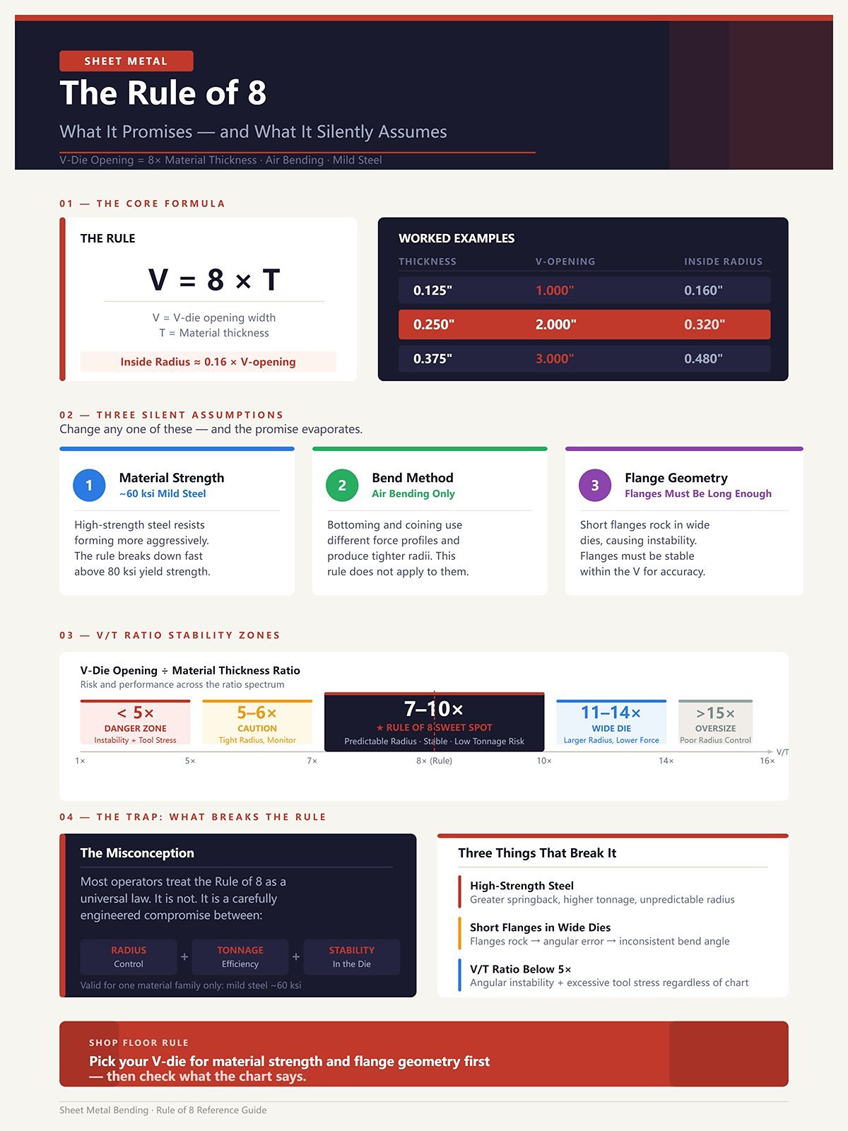
You’ve heard it since you were green: V-die opening equals 8× material thickness.
So 0.125″ material? 1″ V. 0.250″? 2″ V.
What that rule actually promises is a predictable inside radius in mild steel during air bending. Roughly:
Inside Radius ≈ 0.16 × V-opening
Run 1/4″ mild steel in a 2″ V and you’ll see about a 0.32″ inside radius. That’s the math it’s banking on.
But it silently assumes three things:
Change one variable and the promise evaporates.
High-strength steel resists forming. Short flanges rock in wide dies. Go under 5× thickness on V-opening and you risk angular instability and tool stress regardless of what the chart says.
Here is the trap, you think “Rule of 8” is a law. It’s a compromise between radius control, tonnage, and stability—for one material family.
Shop Floor Rule: Pick your V-die for material strength and flange geometry first—then check what the chart says.
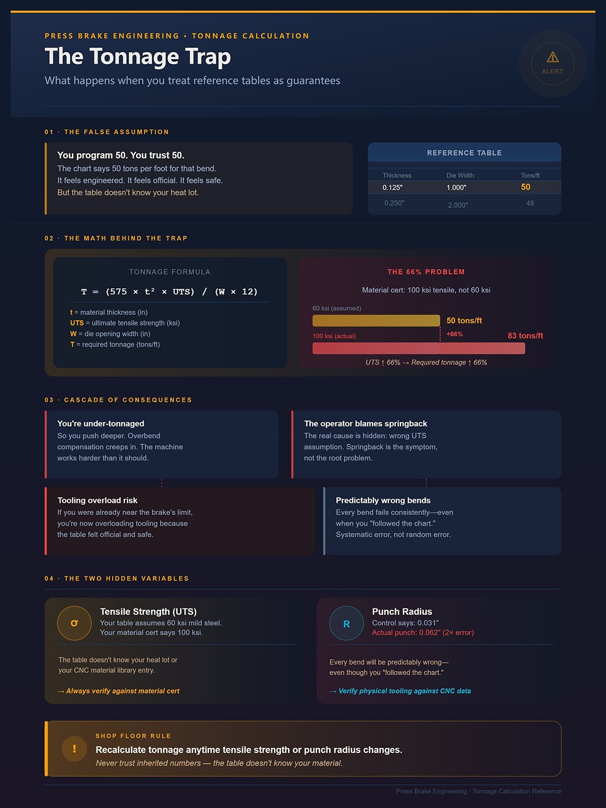
Let’s say the chart tells you 50 tons per foot for that bend.
You program 50. You trust 50.
But the material cert says 100 ksi tensile, not 60 ksi. Go back to the formula:
If tensile strength increases by 66%, required tonnage increases by 66%. That 50 tons per foot just became about 83.
You’re under-tonnaged. So you push deeper. Overbend compensation creeps in. The machine works harder than it should. The operator blames springback.
Or worse—you were already near the brake’s limit. Now you’re overloading tooling because the table felt official.
Here is the trap, the table feels engineered, so it feels safe. But it doesn’t know your heat lot, your punch radius, or your CNC material library entry.
Tonnage tables assume correct data input. If your control says the punch radius is 0.031″ and it’s actually 0.062″, every bend will be predictably wrong—even though you “followed the chart.”
Shop Floor Rule: Recalculate tonnage anytime tensile strength or punch radius changes—never trust inherited numbers.
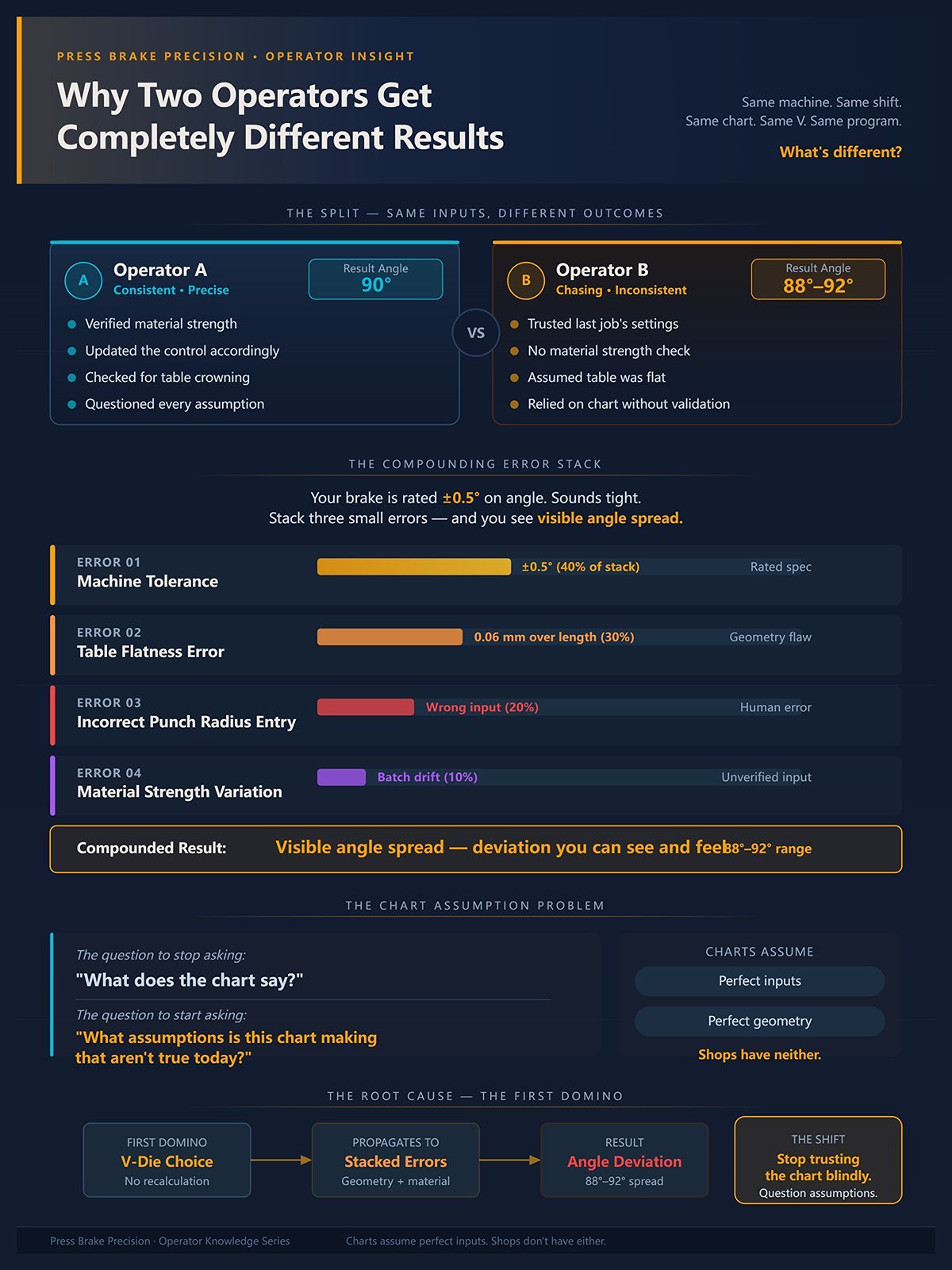
I’ve watched this happen on the same machine, same shift.
Operator A hits 90° clean. Operator B is chasing 88° to 92° all afternoon.
Same chart. Same V. Same program.
What’s different?
One verified material strength and updated the control. The other trusted the last job’s settings. One checked for table crowning. The other assumed flat.
Your brake might be rated ±0.5° on angle. Sounds tight. But stack a small table flatness error (0.06 mm over length), a slight material variation, and an incorrect punch radius entry—and you’ve compounded enough deviation to see visible angle spread.
Charts assume perfect inputs and perfect geometry.
Shops don’t have either.
And that’s the shift I need you to make: stop asking, “What does the chart say?” and start asking, “What assumptions is this chart making that aren’t true today?”
Because the first domino isn’t the angle.
It’s the V-die you chose without recalculating.
Last winter, we had a 1/4″ stainless bracket that “needed a tighter corner.” Operator swapped the 2″ V for a 1.5″ V. Same punch. Same program. First hit sounded different. By the third part, the brake was flirting with max tonnage and the angle still wasn’t consistent.
Nothing else changed.
That’s when it clicks: the V-die isn’t just a groove you drop material into. It’s the first domino. Tip it, and radius shifts, tonnage spikes, flange geometry changes, and tooling life shortens—all before you touch the depth setting.
You want a step-by-step process? Fine. It starts here:
Miss step two, and the rest is guesswork dressed up as experience.
Shop Floor Rule: The V-die choice is not a detail—it’s the decision everything else obeys.
You keep telling me, “Print calls for a 0.250 inside radius.”
No. The print calls for a result. The die determines how you get there.
In air bending, the inside radius is not driven by the punch tip the way beginners think. It’s mostly a function of the V-opening. The working relationship for mild steel at 90° is:
Inside Radius ≈ 0.16 × V-opening
Put 1/4″ mild steel in a 2″ V:0.16 × 2.0 = 0.32″ inside radius.
Not 0.25″. Not whatever the punch nose says on the box. About 0.32″.
Now swap to a 1.5″ V to “tighten it up”:0.16 × 1.5 = 0.24″.
You just changed the inside radius by 0.08″ by touching one variable.
Here is the trap, operators treat inside radius as an input and V-die as a supporting actor. In air bending, it’s the opposite. The die opening largely dictates the natural radius the material forms into. The punch only refines it within limits.
And once you change V, you don’t just change radius. Look at the tonnage formula:
Tonnage per foot = (Tensile Strength × Thickness²) ÷ (8 × V-opening)
Notice what’s in the denominator. V-opening. Shrink V, and tonnage goes up—linearly with V, but exponentially with thickness because of the T² term.
You wanted a tighter radius. You also just demanded more force.
Shop Floor Rule: In air bending, pick the V for the radius you can live with—then accept the tonnage that comes with it.
You’ve heard the Textbook Rule of 8 since day one: V-opening = 8 × material thickness.
That works—for mild steel, 90° air bends, and “normal” geometry.
Run 0.125″ material:8 × 0.125 = 1.0″ V.
Fine. Predictable. Stable.
But say the print demands a tighter inside radius than the 8× setup gives you. You drop to 6×:
6 × 0.125 = 0.75″ V.
Radius drops accordingly:0.16 × 0.75 = 0.12″ inside radius (approx).
Great. But now recalc tonnage.
If original tonnage at 1.0″ V was T, the new tonnage becomes:
T_new = T × (1.0 ÷ 0.75) ≈ 1.33T
That’s a 33% increase just from narrowing the die. No change in thickness. No change in material grade.
Now go the other direction. Heavy plate. 1/2″ mild steel.
Rule of 8 says:8 × 0.5 = 4″ V.
But thick plate often behaves better at 10× or 12× for stability and tool life.
12 × 0.5 = 6″ V.
You just widened the V by 50%. That reduces tonnage:
T_new = T × (4 ÷ 6) ≈ 0.67T
Less force. Bigger inside radius:0.16 × 6 = 0.96″ radius.
Here’s what the charts don’t explain: the multiplier shifts because you’re balancing three competing forces—
Go under 5× thickness on V-opening and you risk angular instability and tool stress regardless of what the chart says. The material has nowhere to flow cleanly. Tool shoulders take abuse. Angles get twitchy.
Here is the trap, you chase the print’s tight radius without recalculating tonnage and forget that thickness is squared in the formula. Double thickness, and required tonnage quadruples. That’s not linear pain. That’s exponential punishment.
You don’t “follow 8×.” You choose 6×, 8×, or 12× based on which compromise hurts you least—and you verify the math every time.
Shop Floor Rule: Abandon 8× the moment geometry, strength, or thickness demand it—then prove your new ratio won’t overload the brake.
Now let’s ruin your perfect setup.
Suppose your 0.125″ part has a 0.500″ flange. You want to run a 1.0″ V (8×). Sounds textbook.
But minimum flange length in air bending is roughly:
Minimum Flange ≈ (V-opening ÷ 2) + material thickness
For a 1.0″ V:(1.0 ÷ 2) + 0.125 = 0.625″
Your flange is 0.500″. It physically can’t sit stable in that die without tipping into the V.
So what do you do? Narrow the die to 0.75″:
(0.75 ÷ 2) + 0.125 = 0.500″
Now it just fits.
But remember what that did? It increased tonnage by roughly 33% and tightened the inside radius.
You didn’t change the print. The flange geometry forced a V-die change. The V-die change forced a tonnage recalculation. The tonnage recalculation may now exceed your machine’s safe working load.
That’s the cascade.
Here is the trap, you pick a V based on thickness and forget the flange has to physically bridge the die shoulders. The part doesn’t care what the chart recommends. It cares about geometry.
And if you ignore that geometry, you’ll see rocking parts, inconsistent angles, or crushed flanges—and you’ll blame springback when the real problem was support.
Shop Floor Rule: Before locking in a V-opening, prove the flange can physically sit in it—then rerun tonnage before you touch the pedal.**
You see where this is headed.
Once the V-die width shifts—even for a good reason—you owe the machine a fresh tonnage calculation and a hard look at capacity. Because the domino you tipped at setup is about to land on your brake’s load limit.
Last month an operator brought me a setup sheet: 1/4″ stainless, 10 feet long, 2″ V-die. Chart said 19.7 tons per foot for 1/4″ mild steel in a 2″ V. He ran the number straight across a 150-ton brake and figured he was safe.
Here is the trap, he verified total tonnage against the badge on the machine and never recalculated for material strength or per-foot loading.
The tonnage formula you should be running—every time—is:
Tons/ft = (Tensile Strength × Thickness²) ÷ (8 × V-opening)
The chart assumes 60,000 PSI mild steel. That stainless was closer to 90,000 PSI tensile. The scaling factor is simple:
Material Multiplier = New Tensile ÷ 60,000
So 90,000 ÷ 60,000 = 1.5×.
Take that 19.7 tons/ft baseline and multiply:
19.7 × 1.5 ≈ 29.6 tons per foot.
Across 10 feet, that’s 296 tons. On a 150-ton machine.
And even if you argue you’re not bending the full 10 feet at once, the machine frame doesn’t care about your optimism. It cares about load per foot and how evenly it’s distributed.
You verify safety in three passes:
Miss any one of those and you’re gambling with a six-figure asset.
Shop Floor Rule: Never trust chart tonnage until you’ve scaled it for real tensile strength and real bend length.
Every standard chart you’ve got is anchored to 60,000 PSI mild steel. That’s the quiet assumption baked into the numbers.
You don’t need a new chart for every alloy. You need a ratio.
Tons/ft_actual = Tons/ft_chart × (Tensile_actual ÷ 60,000)
That’s it. No guessing.
Stainless at 90,000 PSI? Multiply by 1.5. High-strength low-alloy at 100,000 PSI? 100,000 ÷ 60,000 ≈ 1.67×. 5052 aluminum around 38,000 PSI? 38,000 ÷ 60,000 ≈ 0.63×.
But even a 0.63 multiplier can trick you if you narrowed the V to fix a flange problem. Because tonnage is inversely proportional to V-opening:
T ∝ 1 ÷ V
Cut V from 2″ to 1.5″? 2 ÷ 1.5 ≈ 1.33× increase.
So imagine 1/4″ aluminum in a 1.5″ V. You reduced tonnage for material (0.63×) but increased it for die width (1.33×).
Net effect: 0.63 × 1.33 ≈ 0.84× mild steel baseline.
You think aluminum is always “easy.” It isn’t. It’s math.
Here is the trap, operators change material and die width in the same job and only adjust for one of them. The multipliers stack. Sometimes they cancel. Sometimes they double your load.
And none of that shows up on a generic tooling chart.
Shop Floor Rule: Scale the chart by tensile ratio first, then adjust for V-opening—never the other way around.
I’ve seen a 150-ton brake crack a lower die before it ever complained about frame capacity.
Why? Because the die had a 20 tons-per-foot rating, and the job demanded 28.
A common 150-ton × 10′ brake has a distributed rating of about 15 tons/ft if evenly loaded. Some heavier frames get near 25 tons/ft. But that’s machine structure. Your tooling might be rated lower.
Here’s how you check it:
Whichever number is lower is your real ceiling.
Here is the trap, guys look at “150 tons” and forget that bending 3 feet in the center at 45 tons total is 15 tons/ft locally. Shift that to 2 feet and you’re at 22.5 tons/ft in that zone. Same total tonnage. Higher localized stress.
Frames twist. Dies mushroom. Punch shoulders chip.
The badge on the machine is not permission. It’s a limit under ideal distribution.
Shop Floor Rule: Your allowable tons per foot is the smallest number among machine rating, tooling rating, and your calculated load—respect the weakest link.
Charts assume a 90° air bend. That matters.
When you bend to 30° or 45°—an acute pre-bend before closing—the force increases because the material contacts more of the punch and die shoulders. You are no longer in clean, three-point air bending. You’re drifting toward bottoming behavior.
Force increases aren’t trivial. Depending on geometry, you can see 20–50% above the 90° chart value before bottoming.
The math logic is simple even if the exact factor varies:
T_actual ≈ T_90° × Angle_Factor
If your 90° calculation says 20 tons/ft and your acute angle factor is 1.3, you’re at 26 tons/ft before you ever flatten the bend.
Now stack that with a narrow die and stainless multiplier.
This is how operators end up saying, “The numbers said I was fine,” while standing next to a cracked punch tip.
Here is the trap, you verify tonnage at 90° on paper but run the peak load at 35° in reality. The machine feels the peak, not the final angle.
Go under 5× thickness on V-opening and you risk angular instability and tool stress regardless of what the chart says. Add acute angles to that, and you’ve built a stress concentrator.
You started this section asking how to verify you’re within safe working limits. The answer isn’t a single comparison. It’s layered math: material ratio, V-opening adjustment, per-foot distribution, and angle factor—all checked against both machine and tooling ratings.
And even if all that passes, there’s still one more weak point waiting to fail.
The punch.
That’s where the load concentrates next.
Last winter we split a punch tip on 3/16″ stainless. Not because the brake was overloaded. Not because the die was underrated. Because 42 tons of calculated load per foot funneled through a 0.031″ punch nose and nobody stopped to ask what that does to contact stress.
Here is the trap, you verify total tons and tons per foot, compare them to machine and die ratings, and assume the punch is fine because it’s “hardened tooling.” Load doesn’t care about hard. It cares about area.
Contact pressure scales with force divided by contact width. Shrink the punch nose radius and you shrink the contact patch. Same tonnage, higher stress at the tip. That’s how a brake rated safe on paper chips a $900 punch in one hit.
In air bending, your inside radius roughly follows the die: Inside Radius ≈ 0.16 × V-opening (for mild steel baseline). But the punch nose radius is what initiates that bend. If your die is 1.5″ V, predicted inside radius is about 0.24″. Run a 1/32″ (0.031″) punch tip into that and the initial contact zone is razor small until the sheet wraps. On high tensile material, that spike is violent.
You don’t just check tons per foot. You check where that tonnage concentrates.
And the chart never tells you that.
Shop Floor Rule: After calculating tons/ft, compare it against punch nose radius and material strength—small tip plus high tensile equals concentrated risk.
Picture a simple U-bracket: 2″ web, 1″ flanges, 14 ga. First bend goes fine. Second bend, you swing it up and the punch body—not the tip, the shoulder—crashes into the first flange at 62°.
The chart gave you V-opening and tonnage. It said nothing about punch body geometry.
Gooseneck punches exist for this reason. They’re relieved behind the tip so the previously formed flange has somewhere to go. But here is the trap, operators pick the right tip angle and forget the punch body width and relief depth.
Clearance isn’t a guess. Measure it.
If your flange height is H and your punch shoulder sits S behind the tip at the working depth, then you need: H ≥ S + material thickness + safety margin.
If S is 0.75″ and your flange is 0.70″, you will collide. Doesn’t matter what the chart promised.
And when you collide mid-stroke, the brake keeps pushing until tonnage spikes. That spike isn’t in your earlier math. It’s a geometric lock. Now your localized tons per foot jump, your punch sees a shock load, and your nice safe calculation evaporates.
This is why clearance outranks angle in multi-bend parts. Angle can be adjusted with depth in air bending. Physical interference cannot.
Shop Floor Rule: Before approving a punch, dry-cycle the geometry on paper—verify shoulder clearance against flange height or expect a collision spike.
A tooling chart predicts inside radius from die width. It does not tell you the minimum bend radius your material can survive.
Those are not the same number.
Take 304 stainless at around 90,000 PSI tensile. A common minimum inside bend radius guideline is about 1× material thickness for 90° air bends. Bend 0.125″ thick stainless tighter than 0.125″ inside radius and you risk cracking along the grain.
Now apply the die formula: Inside Radius ≈ 0.16 × V. If you chose a 0.5″ V to “tighten the radius,” you get 0.16 × 0.5 = 0.08″ inside radius.
0.08″ < 0.125″. You just forced the material below its minimum safe bend radius.
Here is the trap, you think changing the punch nose radius controls the finished inside radius in air bending. It doesn’t. The die controls it. The punch initiates the bend, but the die width determines the arc.
In bottom bending, different story. There the punch nose must match the die radius to imprint the material. But bottom bending demands 2–4× the tonnage of air bending. That multiplier stacks on everything we already calculated. Now your punch isn’t just shaping—it’s coining.
So you have two separate checks:
Miss either and you’ll see micro-fractures on the outside of the bend before the part leaves the brake.
Shop Floor Rule: Compare predicted inside radius (0.16 × V) to material minimum bend radius before you ever argue about punch tips.
You’ve been told to match angles: 90° punch with 90° die for a 90° bend. Clean and simple.
In air bending, that’s only half true.
The final bend angle is controlled by penetration depth into the die, not strictly by punch angle. An 88° punch in a 90° die can still produce a perfect 90° bend if you manage depth correctly. The sheet only contacts the punch tip and die shoulders during most of the stroke.
So is angle mismatch the villain?
Not automatically.
Here is the trap, the real danger isn’t small angle mismatch in air bending—it’s running out of clearance before you hit depth. If your punch angle is too open relative to your target, you may bottom out the punch shoulders against the material as you chase angle. That shifts you from three-point air bending toward bottoming behavior without planning for it.
And when that happens, tonnage spikes.
Remember earlier: T_actual ≈ T_90° × Angle_Factor.
As you approach acute angles, contact area increases and force rises—20–50% isn’t unusual before true bottoming. If your punch and die angles force early shoulder contact, you’ve effectively increased the Angle_Factor without updating your math.
Now stack that with high tensile and narrow V.
Dominoes fall fast.
Angle mismatch is not automatically wrong. Unplanned contact is.
You don’t verify punch safety by matching catalog angles. You verify it by confirming that, through the full stroke required for your target angle, contact stays where you expect it—tip and die shoulders only—and that the calculated peak tonnage remains under both tooling and punch stress limits.
Which brings us to the discipline you’ve been avoiding.
All these variables—material strength, V-opening, per-foot load, angle factor, punch clearance, minimum radius—must be checked in sequence, not by instinct. One domino at a time.
Shop Floor Rule: In air bending, manage depth—not just angle—and confirm no unintended shoulder contact before trusting your tonnage math.
You want the sequence. Not theory. Not “it depends.” The exact steps that keep your punch alive and your scrap bin empty.
Good.
Because punch safety isn’t a catalog number—it’s a chain of decisions. Tip the first domino wrong and the rest fall fast: radius shifts, tonnage spikes, flanges collide, shoulders touch, and the brake delivers a load you never calculated.
The chart is your starting tile. Not your answer.
Here is the trap, you open the chart before you define the metal.
Tooling charts assume mild steel around 60,000 PSI tensile. That’s the quiet assumption behind most baseline tonnage formulas. One common form:
P = (650 × S² × L) / V
Where:
P = force in tons
S = thickness (inches)
L = bend length (inches)
V = die opening (inches)
The 650 constant assumes mild steel in air bending.
Now swap to 90,000 PSI stainless. Your strength multiplier is:
Multiplier = 90,000 / 60,000 = 1.5
Every tonnage value must be multiplied by 1.5 before you do anything else.
If you’re bottoming instead of air bending, add another 2× to 4× depending on penetration. Air bending typically needs 20–30% less force than bottoming, even with the same geometry.
So your corrected tonnage becomes:
P_corrected = P_chart × Material Multiplier × Method Multiplier
You do this before picking a V-die, because that multiplier follows you into every later decision.
Define tensile. Define bend method. Write the multiplier at the top of your setup sheet.
Shop Floor Rule: No material multiplier written down, no chart opened.
Now that the metal has a personality, what V-opening actually makes sense?
The V-die is the first domino.
Textbook Rule of 8 says V ≈ 8 × thickness for mild steel air bends. It’s a baseline, not a commandment.
Because V controls three things at once:
Inside radius in air bending is roughly:
Inside Radius ≈ 0.16 × V
If your print demands a 0.125″ inside radius, then:
V = 0.125 / 0.16 = 0.78″
So you’re in the neighborhood of a 3/4″ V.
But that same V determines minimum flange length. A practical rule for air bending minimum flange is about:
Min Flange ≈ V / 2
Run a 1″ V? You need about 0.5″ flange just to seat properly. Try bending a 0.4″ flange in that die and the part will tip into the opening. Angle won’t repeat. Tonnage won’t distribute evenly.
Go under 5× thickness on V-opening and you risk angular instability and tool stress regardless of what the chart says.
Here is the trap: operators choose V by thickness rule and only later discover the flange is too short or the radius is too tight. Then they narrow the V to “make it work” without recalculating tonnage.
Narrower V means higher force because tonnage is inversely proportional to V:
P ∝ 1 / V
Cut V from 1″ to 0.5″? You just doubled baseline force before multipliers.
So you lock V based on radius and flange geometry first. Then you recalculate tonnage with your real multipliers. Not the other way around.
Shop Floor Rule: Choose V for radius and flange reality, then accept the tonnage consequence.
Once V is locked, the math gets serious.
Now we combine everything.
Start with the formula:
P = (650 × S² × L) / V
Then apply:
P_total = P × Material Multiplier × Method Multiplier
Then convert to tons per foot if needed:
Tons/ft = P_total / L (in feet)
Your machine has two limits: total tonnage and tonnage per foot. Your tooling also has a tons-per-foot rating. The lowest number in that chain is your ceiling.
But even a 0.031″ punch tip concentrates load brutally. Tons per foot is not evenly spread across the punch body—it’s focused along that tiny contact line. That’s where cracking starts.
Here is the trap, adding a casual 20% “safety margin” without checking machine or tool rating. I’ve seen operators calculate 40 tons/ft, add 25% “just to be safe,” and quietly push past a 50 tons/ft tooling rating.
Safety margins don’t override limits. They must sit inside them.
So your verification checklist looks like this:
If any answer is “close,” it’s not safe yet.
Shop Floor Rule: The lowest rated component decides what’s safe—not your optimism.
Math says it works. Geometry says it clears. Now you prove it in steel.
The first hit is not production. It’s a diagnostic.
You measure four things:
If predicted radius was 0.16 × V and you measure tighter than expected, you may be drifting toward bottoming. That means higher real tonnage than calculated.
If angle jumps rapidly near final depth, shoulders may be touching early. That’s unintended contact. That’s a spike waiting to happen.
If the flange rocks or sinks into the die, your V is too wide for the geometry—even if the chart approved it.
And if you see bright witness marks on punch shoulders instead of just the tip, stop. That’s geometry rewriting your tonnage math in real time.
This loop is simple:
Predict → Hit light → Measure → Compare → Adjust → Recalculate.
Not “predict and hope.”
You are not verifying the chart. You are verifying that the metal, the geometry, and the load all match your assumptions.
Because the only chart that matters is the one that matches the metal in your hands.
Shop Floor Rule: First hit is for proof, not parts—measure everything before committing the run.
| Step | Title | Key Content | Formulas | Shop Floor Rule |
|---|---|---|---|---|
| Step 1 | Define material behavior and multipliers before touching the chart | Tooling charts assume mild steel (~60,000 PSI tensile). Switching materials requires applying a strength multiplier. Bottoming requires 2×–4× more force than air bending. Define tensile strength and bend method before selecting tooling. | Baseline formula: P = (650 × S² × L) / V P = force (tons) S = thickness (in) L = bend length (in) V = die opening (in) Material Multiplier: Multiplier = Tensile / 60,000 Corrected tonnage: P_corrected = P_chart × Material Multiplier × Method Multiplier | No material multiplier written down, no chart opened. |
| Step 2 | Lock in the V-die based on radius targets and flange reality | V-die selection controls inside radius, tonnage, and minimum flange length. Rule of 8 (V ≈ 8 × thickness) is a baseline only. Narrowing V increases force. Always choose V based on radius and flange requirements first, then recalculate tonnage. | Inside radius (air bend): Inside Radius ≈ 0.16 × V Minimum flange: Min Flange ≈ V / 2 Tonnage relationship: P ∝ 1 / V | Choose V for radius and flange reality, then accept the tonnage consequence. |
| Step 3 | Verify total tonnage against machine and tool limits | Calculate total tonnage including multipliers. Check both total machine capacity and tons per foot limits. Tooling ratings and load concentration at punch tip are critical. Safety margins must remain within equipment limits. | Total tonnage: P_total = P × Material Multiplier × Method Multiplier Tons per foot: Tons/ft = P_total / L (ft) | The lowest rated component decides what’s safe—not your optimism. |
| Step 4 | The verification loop—what to measure on first test hit | First hit is diagnostic. Measure inside radius, bend angle at partial stroke, flange stability, and contact pattern. Watch for signs of bottoming or unintended contact. Follow a structured verification loop before production. | Verification loop: Predict → Hit light → Measure → Compare → Adjust → Recalculate | First hit is for proof, not parts—measure everything before committing the run. |


