

Last spring a kid ran a 10-foot strip of 11-gauge stainless—$312 worth of material—through a perfectly “safe” setup. Calculator said 74 tons. Our 135-ton press didn’t even grunt.
Both legs came out 1/8 inch short.
The machine was fine. The part was trash. That gap between “safe hit” and “correct part” is where most young operators live without knowing it.
You punch in thickness, tensile strength, die opening, bend length. The calculator spits out a clean number—green light. It feels like math has your back.
What it actually told you is this: if you push this much force into this much steel over this many inches, the frame won’t twist and the hydraulic system won’t overload. It answered a machine question.
Your customer isn’t buying machine safety. They’re buying two legs that measure 2.000 inches when the calipers close.
So what happens when those two questions drift apart?
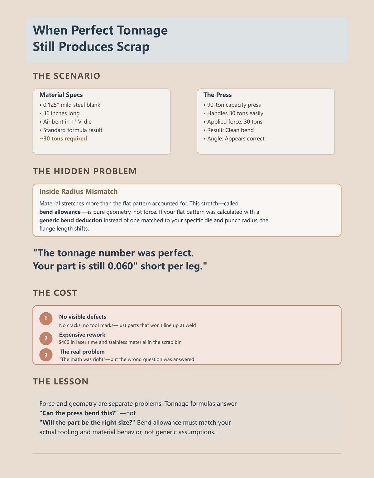
Picture a 0.125-inch mild steel blank, 36 inches long, air bent in a 1-inch V-die. The standard formula—material strength × thickness squared ÷ die opening, all multiplied by bend length—says you need roughly 30 tons. Your 90-ton press handles it easy.
You hit 30 tons. The bend forms clean. Angle looks right.
But the inside radius isn’t what your print assumed. The material stretches more than your flat pattern accounted for. That stretch—bend allowance—is geometry, not force. If your flat was calculated with a generic bend deduction instead of one matched to that 1-inch V-die and that punch radius, your flange length shifts.
The tonnage number was perfect.
Your part is still 0.060 short per leg.
Scrap Bin Warning: This is the kind of error that doesn’t look dramatic. No cracks. No tool marks. Just a stack of parts that won’t line up at weld, and $480 in laser time and stainless sitting in the red bin because “the math was right.”
So if the force was right, what question did we actually answer?
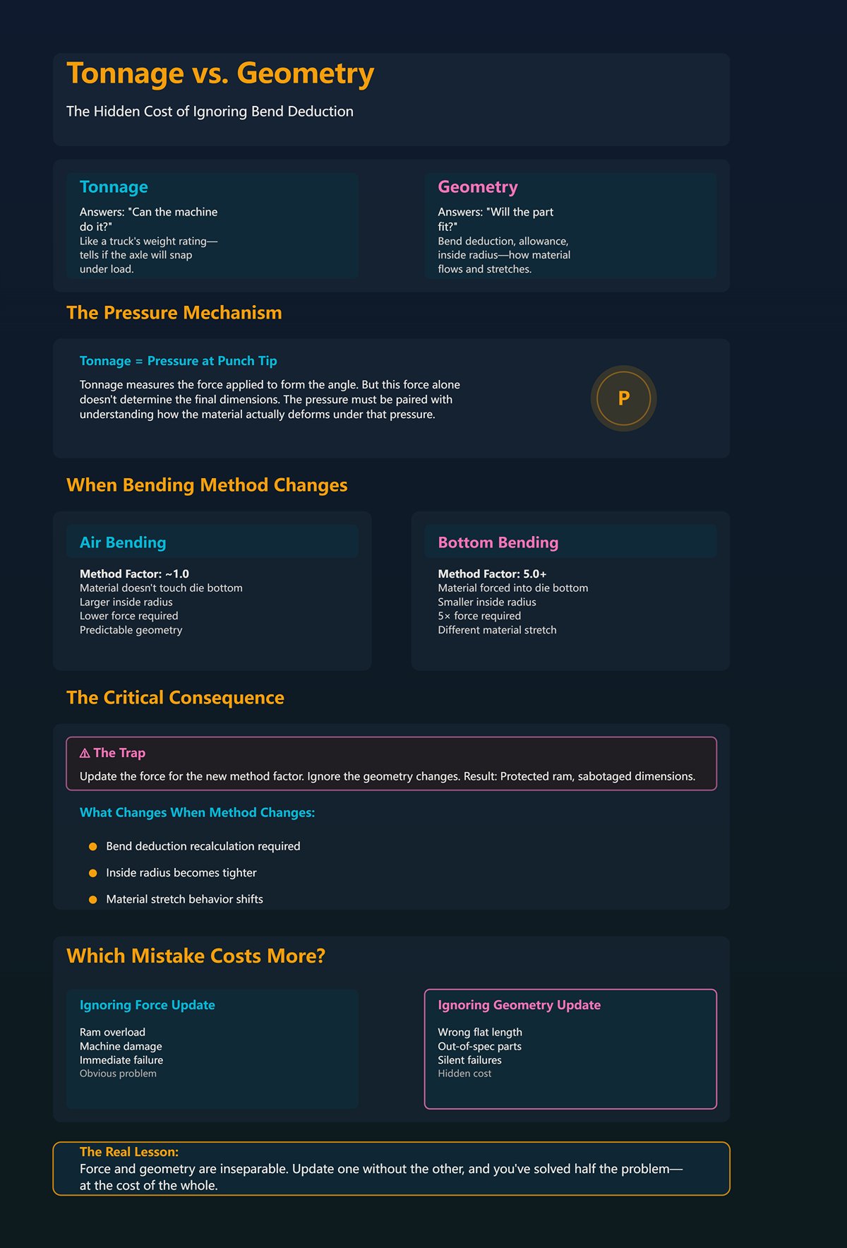
Think of tonnage as the weight rating on a truck. It tells you whether the axle will snap under load. It does not tell you whether the cargo will shift and crush itself before you reach the job site.
In bending terms, tonnage is about pressure at the punch tip. Geometry—bend deduction, bend allowance, inside radius—is about how the material flows and stretches as that pressure forms the angle.
Change from air bending (method factor around 1.0) to bottom bending (5.0 or more), and the required force can jump fivefold. The calculator adjusts tonnage for that method factor. Good. The press survives.
But your bend deduction changes too, because bottom bending forces the material tighter into the die. Smaller inside radius. Different material stretch. Different flat length required before you ever touch the pedal.
If you update the force and ignore the geometry, you protected the ram and sabotaged the dimensions.
Which mistake costs more in the long run?
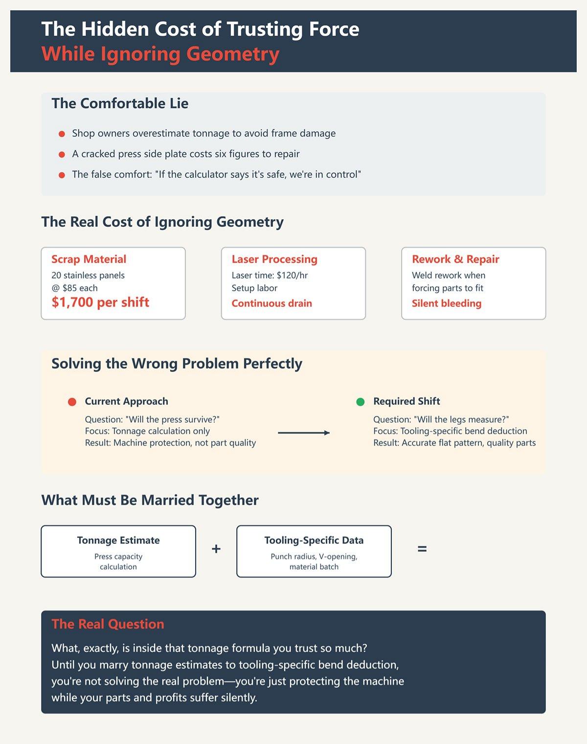
Some shop owners overestimate tonnage on purpose. They’d rather wear a machine a little faster than snap a frame. I understand that instinct. A cracked press side plate is a six-figure nightmare.
But scrapping twenty 4-foot stainless panels at $85 each is $1,700 gone in a shift. Add laser time at $120 an hour, setup labor, and the weld rework that follows when someone tries to “make it fit.” You’re bleeding cash quietly instead of dramatically.
The comfortable lie is this: if the calculator says the hit is safe, the job is under control.
It isn’t under control until the tonnage estimate is married to tooling-specific bend deduction—meaning the exact punch radius, exact V-opening, exact material batch are reflected in your flat pattern.
Until you make that shift—from “Will the press survive?” to “Will the legs measure?”—you’re solving the wrong problem perfectly.
And that raises the real question: what, exactly, is inside that tonnage formula you trust so much?
On most shop calculators, you type four things: material tensile strength, thickness, die opening, bend length. Hit enter. Out comes a tonnage number.
Under the hood, that “standard” air-bend formula is doing something simple: Force per foot = (material strength × thickness²) ÷ die opening, then multiplied by length. Thickness gets squared. Die opening sits in the denominator. Tensile strength scales the whole thing.
Now translate that into shop-floor actions.
That’s clean math. It protects the frame.
But look at what’s missing. There’s no punch radius in that equation. No neutral axis location. No springback term. No K-factor — that ratio that tells you how deep inside the thickness the metal actually stretches. The formula assumes a “typical” air bend where the inside radius forms as a predictable fraction of the V-opening, and the neutral axis behaves itself.
Assumes.
It’s like loading a truck based only on weight rating. The axle won’t snap. Good. But the formula never asked how the load is strapped down.
Scrap Bin Warning: When you treat that tonnage output like it also predicts inside radius, you’ll see parts that are consistently 0.040–0.090 short per flange. They look clean. Angles check. But the flat was built on a radius the formula never promised you.
So if die opening sits in the denominator, what actually happens to the metal when you change it?
I watched a foreman once swap a 1-inch V for a 1.5-inch V on 10-gauge mild steel because the press was getting close to its comfort zone. Calculator said the tonnage would drop by a third.
It did.
The ram felt lighter. The pump ran cooler. Everybody relaxed.
What changed physically? With a wider V-die, the sheet spans a longer gap before it yields. The punch has to travel deeper to achieve the same angle because the material is bending over a broader base. That increases the resulting inside radius — in air bending, inside radius is typically some fraction of the V-opening. Open the die wider, and the radius grows with it.
Now think in stretch, not force. The outside fibers of the bend have to travel farther around that larger radius. That changes how much material is pulled from the flanges into the bend zone. And the neutral axis — the imaginary layer inside the thickness that neither stretches nor compresses — shifts position as strain distribution changes.
You didn’t just “reduce tonnage.” You altered the geometry of stretch.
And your flat pattern? It was calculated with a bend deduction tied to the old die. That deduction assumed a smaller inside radius and a certain neutral axis position. With the wider die, more material stays in the legs and less is consumed in the arc — or vice versa, depending on thickness-to-radius ratio. Either way, it’s different.
The calculator celebrated because the press survived. The weld table cursed because the box grew 0.125 in width across four bends.
Scrap Bin Warning: This error shows up as assemblies that rock on a flat table. Diagonals don’t match. You’ll chase it with clamps and heat, not realizing the real mistake happened when someone widened the V without updating the bend deduction.
So if die width silently changes stretch, what happens when you change the entire bending method?
Air bending and bottoming can share the same material, thickness, and die opening — and demand completely different physics.
Air bending uses partial contact. The punch presses the sheet into the V, but the material never fully conforms to the die walls. Angle is controlled by punch depth. Springback is real and must be overbent. Tonnage is relatively low.
Bottoming forces the sheet to contact the die faces more completely. The material is driven closer to the die angle. Springback drops. Accuracy improves. Tonnage can jump five to thirty times higher than air bending for the same thickness.
The calculator usually handles this with a “method factor.” Multiply the air-bend tonnage by five or more for bottoming. Machine protected. Frame intact.
But here’s the part young operators miss: bottoming also forces a tighter, more die-controlled inside radius. You’re not letting the material choose a natural air-bend radius based on V-opening; you’re imposing one closer to the punch and die geometry. That changes how severely the outer fibers stretch and where the neutral axis settles.
If your flat pattern was built around an air-bend K-factor and you bottom the part to fix angle inconsistency on an older press, you just changed the material flow without telling your bend deduction.
The calculator doesn’t care. It answered the force question you asked.
Scrap Bin Warning: This mistake shows up as parts that hit angle dead-on but miss flange length every time — consistent error, batch after batch. You’ll blame the backgauge before you admit the bending method changed the stretch.
And even if you lock down die width and method, there’s one variable the formula treats like a polite suggestion.
Take two sheets labeled “A36 mild steel.” One tests at 58 ksi tensile. The next heat comes in at 72 ksi. Both legally sold as the same grade.
Plug 60 ksi into the calculator and you’ll get a comfortable tonnage number. But that higher-strength sheet resists yielding longer. The punch travels deeper before the bend forms to the same angle. Deeper penetration in air bending usually means a slightly smaller effective inside radius and different springback behavior.
Same die. Same stroke setting. Different stretch.
Higher tensile strength also shifts the neutral axis toward the inside of the bend because the material can sustain higher stress before yielding. That alters the proportion of thickness in tension versus compression. Bend allowance changes — not dramatically in every case, but enough that across multiple bends, you stack error.
The formula scales force linearly with tensile strength. It does not scale geometry with the same sensitivity.
Last spring a kid ran a 10-foot strip of 11-gauge stainless—$312 worth of material—through a perfectly “safe” setup. Calculator said 74 tons. The press had capacity to spare. But the stainless batch was stiffer than the last run. Same program. Same die. The flanges walked short.
The machine answered the force demand. The metal answered with different stretch.
Scrap Bin Warning: Watch for first-article parts that measure fine on angle but require a 0.020–0.030 backgauge tweak per flange compared to last batch. If you “correct” that without updating the bend deduction tied to tensile strength, you’re baking instability into every future run.
Now you see the pattern. Thickness squared. Die opening divided. Tensile strength multiplied. Method factor applied. All of it built to keep iron from breaking.
But every one of those inputs also nudges how the metal stretches, where the neutral axis sits, and how much flat length disappears into the bend.
So the real question isn’t whether the calculator is wrong.
It’s whether you’re going to let a force equation dictate a geometry problem.
You’re standing at the brake with a part print that calls for two 2.000-inch flanges and a 4.000-inch web in 0.250-inch A36. You check the tonnage chart: over a 2-inch V-die it wants 19.7 tons per foot — 197 tons over 10 feet. Your 150-ton press won’t like that. So you bump to a 3-inch die. Now you’re at roughly 139 tons. Machine safe. Green light.
But the print’s flat pattern was built assuming the smaller die’s inside radius.
That’s the moment most shops miss. The die you chose to protect the press just changed the bend allowance — the length of material consumed in the arc — and your calculator never told you that happened. If the tonnage formula only answers “Will I overload the machine?”, then what answers “Will my flanges land on size?”
I watched a foreman swap a 1.5-inch V for a 2-inch V on 0.125 stainless because the original setup felt “heavy.” The tonnage dropped. The press stopped groaning. Everyone relaxed.
The parts grew.
In air bending, inside radius isn’t a number from the print — it’s a function of die opening and material. A wider V-die generally produces a larger inside radius. Larger radius means the outer fibers stretch less severely per degree, and the neutral axis — the layer that doesn’t change length — shifts position within the thickness. Bend allowance changes because you physically changed how much metal is stretching versus compressing.
Your tonnage calculation passed because it only evaluates force: thickness squared, tensile strength multiplied, divided by die opening. It has no idea where the neutral axis moved. It doesn’t care how much arc length replaced straight leg.
So the machine survives while the flat pattern lies.
Scrap Bin Warning: This shows up as consistent flange growth — 0.030 long on every leg of a four-bend part. Angle is perfect. Backgauge is repeatable. Assemblies won’t square, and you’ll waste $180 in hardware before admitting the die swap altered bend deduction, not operator skill.
If die width changes geometry, then the next question is obvious: how are you choosing the K-factor that drives your bend allowance in the first place?
Most CAD systems default to a K-factor around 0.33. That’s a polite guess — it assumes the neutral axis sits roughly one-third of the way in from the inside surface during bending.
Now picture what actually happens on the floor. You run 0.187-inch 304 stainless in a 1.5-inch V-die with a sharp punch nose. Stainless has higher yield strength and more springback than mild steel. You overbend to compensate. The punch penetrates deeper before the angle sets. The material yields differently than A36.
That physical reality shifts the neutral axis.
K-factor isn’t a magic material constant. It’s a description of where the neutral axis ends up for that thickness, that die opening, that punch radius, that method. Change any one of those and you’ve moved it. If you selected a wider die to drop tonnage from 160 tons to 120 tons, you also influenced inside radius — which changes the strain distribution through thickness — which changes K.
So deriving K from a generic chart while choosing dies based on tonnage is like setting your backgauge off last year’s job because “it was close.”
The disciplined way is backward from the floor: run a test bend with the exact tooling, measure actual inside radius, measure flange lengths, calculate real bend allowance, then solve for K that matches reality. Now your flat pattern reflects your physical setup, not a software default.
You don’t guess the neutral axis. You let the metal show you where it went.
And once you accept that K depends on tooling, you start seeing the loop you’ve created between force and geometry.
Take that 1.5-inch V versus 2-inch V example. Narrower die means tighter inside radius in air bending. Tighter radius increases strain on the outer fibers. Higher strain demands more force to yield the material. That’s why the tonnage spikes when you close the die opening.
So you widen the die to protect the press. Force drops because the material isn’t being bent as tightly. But that same relaxation increases inside radius, which reduces bend allowance per degree.
Less force. Different radius. Different flat length.
It’s a closed loop:
Every time you solve the force problem, you’ve already touched the geometry problem.
And if you think material strength stays polite inside that loop, it doesn’t. A batch of 201 stainless can require dramatically different force than 304 for the same thickness. Higher yield pushes you deeper before forming, subtly tightening effective radius in air bending. The tonnage formula scales up linearly with tensile strength. The geometry response is not linear, because strain distribution through thickness shifts with yield behavior.
That’s why two coils stamped with the same thickness can demand different backgauge tweaks even when your calculator swears the tonnage is correct.
So when does this integration stop being a “nice to have” and start being the thing that decides whether you ship parts or excuses?
It happens the instant your calculated tonnage falls comfortably below machine capacity.
If your 150-ton brake only needs 110 tons for the job, force is no longer the constraint. Geometry is. From that point forward, the difference between a good part and a scrap part is measured in thousandths of bend allowance, not tons of pressure.
“Calculator said 74 tons.” I’ve heard that like it’s a badge of honor. Safe. Conservative. Approved.
But the inside radius isn’t what your print assumed.
Once you’re operating inside the machine’s safe envelope, obsessing over another 5 tons of margin does nothing for part accuracy. What matters is whether your bend deduction reflects the actual die, punch, material, and method sitting in the machine right now.
Scrap Bin Warning: The failure shows up as parts that assemble only after “massaging” — slots need filing, bolt holes fight alignment, welders pull joints together with clamps. You’ll blame tolerance stack-up. The real culprit is that your flat pattern was calculated with yesterday’s bend deduction and today’s tonnage-driven tooling.
So here’s the discipline: choose tooling to stay within machine and tooling ratings — in the correct units, with real tensile values — then immediately validate and lock bend allowance from that exact setup before releasing the flat pattern to production.
Force keeps the press alive.
Integrated bend deduction keeps the parts alive.
And if you want this to stop being tribal knowledge and start being repeatable, we need a workflow that ties those two steps together every single time.
Last month a shop owner called me over a “mystery growth” problem. 3/16-inch 304 stainless brackets. Print was right. Laser was dead on. Brake operator swore the setup was safe because the calculator said 118 tons on a 150-ton machine. Every flange came out long by .060.
The tonnage was fine.
The geometry wasn’t.
So here’s the workflow I make every shop follow. Not theory. A repeatable sequence that keeps the press alive and the parts honest. You start with force so you don’t break iron. You end with measured bend deduction so you don’t ship scrap. Miss either one and you’ll learn the lesson in dollars.
Let’s walk it.
Picture 1/4-inch A36 over a 2-inch V-die. The standard chart shows about 19.7 tons per foot. On a 10-foot bend, that’s 197 tons. Too much for a 150-ton brake. Open the die to 3 inches and you drop to roughly 139 tons over the same length. Now you’re inside capacity.
That’s what the calculator is for: guardrails.
But you don’t punch in thickness and walk away. Thickness in the formula isn’t an abstract “t.” It’s the actual micrometer reading off that coil. Because tonnage scales with the square of thickness. If your “.250 plate” measures .265, that’s not 6% more force. It’s closer to 12% more. That’s how you crack a lower die shoulder and swear the tooling was defective.
And length matters. Charts quote tons per foot. If you’re bending 36 inches, multiply by 3. I’ve seen operators glance at “15 tons per foot” and think the job needs 15 tons. Then they run a 4-foot flange and load 60 tons into a tool rated for 50.
The calculator is your first filter. Confirm:
Now you know whether the machine survives the setup.
But the moment you change that die opening to get under capacity, you’ve already changed the inside radius. And that means you’ve changed the flat pattern math whether you admit it or not.
So what did that die swap just do to your geometry?
In air bending, inside radius is not what the punch nose says. It’s roughly proportional to the V-die opening. Mild steel often lands around 16% of the die opening. Stainless runs tighter. Aluminum looser. That’s not folklore. That’s strain distribution through thickness responding to yield strength and die geometry.
Open that 1/4-inch A36 job from a 2-inch die to a 3-inch die to save tonnage, and your inside radius grows with it. If your print called for a .250 inside radius and your new die produces closer to .480, your bend allowance just moved.
Not by magic. By mechanics.
Larger die:
So before you approve that “safe” tonnage number, you check: does this die produce an inside radius compatible with the print?
If the print is tight and cosmetic, you may not have the luxury of widening the die just to save force. Or you redesign the flat pattern intentionally around the new radius. What you do not do is pretend the radius stayed the same.
And here’s the trap most calculators won’t warn you about: tooling ratings are unit-sensitive. A tool stamped 81 tons per foot (short ton) is not the same as 81 metric tons per meter. Acute punches concentrate force outward and reduce safe limits. If you don’t reconcile units and geometry, your “safe” setup can still overstress the tooling shoulders.
Force first. Then radius reality check.
Now that you’ve locked the die based on both capacity and radius, the real money decision is sitting in front of you.
What flat length are you going to cut?
This is where shops either act like professionals or gamblers.
Once die width is fixed, you estimate inside radius based on material and opening. From that radius, thickness, and bend angle, you calculate bend allowance. From bend allowance, you derive bend deduction — the amount you subtract from total flange lengths to get flat.
Those aren’t variables on a screen. They’re physical consequences of:
If your die change increased inside radius from .250 to .480, your bend allowance per 90 degrees might shrink by roughly .050 to .080 depending on thickness and material. On a two-bend part, that’s .100 to .160 difference in flat.
On stainless, that’s the difference between drop-in fit and fighting a weld fixture with a dead blow.
And you do this before you cut production blanks. Not after the first pallet is sheared.
Last spring a kid ran a 10-foot strip of 11-gauge stainless—$312 worth of material—through a perfectly “safe” setup. Tonnage was fine. Machine was happy. Every part was .090 long across two flanges because the flat was programmed off a generic K-factor. They scrapped the strip, blamed springback, and adjusted the backgauge.
Backgauge didn’t cause it.
The flat did.
Scrap Bin Warning: This error shows up as consistent dimensional drift across every part in the batch — all long or all short by the same amount. Operators start “walking” the backgauge to compensate. Now you’ve buried a math mistake inside a setup tweak, and the next job inherits the chaos.
You’ve calculated the deduction. You’ve cut one blank.
Do you trust the math — or do you make the metal prove it?
One blank. Exact production tooling. Exact bend length. No shortcuts.
Bend it.
Measure:
Now compare measured flange sum to flat minus theoretical bend deduction. If you’re off .015, adjust deduction. If you’re off .060, something in your radius assumption was wrong — or your material batch is behaving differently than the book.
This is where you solve for real K-factor from reality, not software default. You let the part tell you where the neutral axis went.
It takes ten minutes.
It saves hours.
When the numbers align — when calculated bend deduction matches measured outcome — you lock the flat pattern and release production. Now your tonnage is safe, your radius is intentional, and your geometry is proven under load.
That’s a verified setup.
But even with this workflow, material variability, grain direction, and batch-to-batch tensile shifts can still nudge results. And that’s where the limits of any calculator-driven model start showing themselves.
| Step | Title | Key Actions | Critical Calculations / Checks | Risks if Ignored | Key Outcome |
|---|---|---|---|---|---|
| Step 1 | Establish Safe Baseline Tonnage | Use brake press calculator before setup | Confirm actual thickness (micrometer reading), tensile strength (if known), bend length, die opening; multiply tons per foot by actual bend length; remember tonnage scales with thickness² | Overloading machine or tooling; cracked die shoulders; unit confusion (short ton vs metric); exceeding tool rating | Machine and tooling operate within safe capacity |
| Step 2 | Cross-Check Die Width vs Target Inside Radius | Verify die opening supports required inside radius | Inside radius ≈ proportional to V-die opening (e.g., ~16% for mild steel); larger die → larger radius → neutral axis shift → reduced bend allowance per degree | Incorrect bend allowance; dimensional errors; cosmetic or fit failures; overstressed tooling due to geometry mismatch | Die selection aligns both with capacity limits and print requirements |
| Step 3 | Calculate Bend Deduction Before Cutting | Determine flat length from real geometry | Estimate inside radius from die + material; calculate bend allowance from radius, thickness, angle; derive bend deduction; adjust for material behavior and springback | Consistent dimensional drift (all parts long/short); scrap material; masking math errors with backgauge adjustments | Accurate flat pattern before production cutting |
| Step 4 | Run Controlled Test Bend | Validate calculations with one production blank | Measure actual inside radius, flange lengths, final angle; compare measured results to theoretical bend deduction; adjust K-factor if needed | Batch-wide errors; incorrect K-factor assumptions; production scrap | Verified setup: safe tonnage, correct radius, proven geometry under load |
You ran the test bend. You measured. You adjusted the bend deduction until the flange lengths landed dead on.
Now a new skid of steel shows up from a different heat number.
Do you rerun everything — or do you trust yesterday’s numbers?
Here’s the line you need burned into your head: the calculator and your first calibration prove what that specific sheet did under that specific load. They do not prove what the next batch will do. Steel isn’t a PDF. It’s a chemical recipe poured hot and cooled at a rate you don’t control.
The calculator is the guardrail. Calibration is steering. But the road still curves.
And curves don’t care what number your calculator printed.
Springback is just elastic recovery. You shove the punch down, the material yields past its yield strength, then when you release pressure, the elastic portion of the strain snaps back and opens the angle.
Simple in theory.
But the amount it snaps back depends on actual yield strength in that sheet — not the “mild steel” button you clicked. If one batch yields at 42 ksi and the next at 50 ksi, the stronger batch springs back more. Same die. Same punch. Same programmed depth. Different angle.
That means different effective inside radius. And that means your bend allowance shifts even if you never touch the setup.
But the inside radius isn’t what your print assumed.
Picture what that means physically. You are commanding the ram to stop at a certain depth — that’s your variable in the real world. Depth equals penetration into the V-die. Penetration controls how tightly the material wraps. If the material fights harder, it relaxes more when you let off. The neutral axis — that imaginary layer that doesn’t stretch or compress — migrates differently through thickness.
You didn’t change math.
The metal did.
Scrap Bin Warning: Springback drift shows up as angles that measure 89 degrees one week and 87.5 the next with the same program. Operators start bumping ram depth by .010 here, .015 there, chasing angle. Now your bend deduction is off, and flange lengths creep long or short by .030 across a 4-flange box. It fits yesterday’s fixture. Today it rocks.
So what happens when the variability isn’t just strength — but structure?
Roll a sheet at the mill and you stretch its grain like pulling taffy. Bend parallel to that grain, and it behaves stiffer. Bend across it, and it yields easier.
Same thickness. Same alloy. Different response.
A calculator collapses all that into one input: “Material = A36” or “Material = 304 stainless.” That’s a category. Reality is batch-to-batch, coil-to-coil, sometimes sheet-to-sheet.
I’ve seen two lifts of 10-gauge hot-rolled — same supplier, same spec — differ enough that one needed .020 more ram depth to hit 90 degrees in the same 1.5-inch V-die. That .020 doesn’t just fix angle. It changes wrap. It nudges inside radius. It shifts bend allowance by a few thousandths per bend.
On a single bracket, who cares.
On a 12-bend enclosure, you just stacked error twelve times.
Last spring a kid ran a 10-foot strip of 11-gauge stainless—$312 worth of material—through a perfectly “safe” setup. Tonnage was fine. Machine was happy. But the new batch had higher yield, springback opened the angles a hair more, and every return flange grew just enough that the final assembly was .080 wide. They forced it into a weld jig. It bowed like a banana after cooling.
They blamed the welder.
The grain didn’t care about their blame.
Here’s the shop-floor translation: grain direction is a physical orientation you can see on the sheet edge. Batch variation is a different stress-strain curve hiding inside what looks identical. Neither variable exists inside your calculator unless you measure and adjust.
And if the material can drift, what about the tools doing the bending?
Your V-die shoulders are not immortal. Every bend is concentrated pressure along two lines of contact. Over time, those shoulders peen — microscopic deformation that slightly widens the effective opening.
Wider opening means larger inside radius.
Larger radius means smaller bend allowance per degree.
You won’t see it on day one. You’ll see it when parts start trending .015 short across the flange and nobody changed the program.
Now add crowning — the deliberate upward bow in the bed to counteract deflection under load. If crowning is mis-set, the center of a long bend sees different penetration than the ends. That’s not theory. That’s ram depth physically varying along length.
Different penetration equals different angle.
Different angle across the same part equals twist, oil-canning, assembly fights.
No calculator knows how worn your die is. No formula knows if the bed is perfectly crowned for today’s tonnage per foot. “Calculator said 74 tons” tells you nothing about whether that force is distributed evenly across 8 feet or concentrated slightly heavier in the center because of deflection.
That’s why this is the boundary line.
On one side: formulas, categories, estimates. On the other: measured angle, measured radius, measured flange — and a habit of checking them again when material, tooling, or length changes.
You don’t control variability by trusting better software.
You control it by building a feedback loop tight enough that the metal never surprises you twice.
You’ve verified the setup. Test bend is good. Angle hits 90. Flange measures dead on.
Then the next lift of material shows up.
Same spec on the tag. Same thickness on the mic. But angles start opening half a degree more, and your second flange is drifting .020 long. Now you’re staring at a “correct” program that’s slowly turning good blanks into rework.
So how do you control batch-to-batch variation once the theory is proven?
You stop acting like someone who inputs numbers and start acting like someone who owns the system.
A calculator user asks, “What’s the tonnage?” A process owner asks, “What changed in the system?”
Force, tooling, grain direction, actual yield strength, bed deflection, even where along the frame you’re applying load — they’re not separate topics. They’re one mechanical event happening under 60, 100, sometimes 200 tons of pressure. When one variable drifts, geometry drifts. If you don’t have a way to catch and correct that drift, the calculator becomes a false sense of security.
The non-obvious part? Machine precision is usually not the problem. Modern brakes hold angle within about half a degree when everything else is stable. Positioning repeatability is tighter than most operators measure. The instability lives in the material and tooling ecosystem around the ram.
Ownership starts there.
When you punch numbers into a calculator, you’re doing one thing: checking whether the truck is too heavy for the bridge.
That’s it.
“Calculator said 74 tons.” Good. The machine won’t overload. But that number says nothing about whether you’re applying those 74 tons across 4 feet or 10, whether you’re inside 60% of frame width, or whether your die manufacturer rated that tool in short tons per foot at 30 degrees instead of 90.
I’ve seen two dies both stamped “80 ton/ft” that meant completely different things because the suppliers used different rating methods. One assumed a shallow bend. The other assumed bottoming. Same stamp. Different reality. If you don’t decode that before you ever open the calculator, you’re building math on sand.
And then there’s the quiet tradeoff nobody talks about online: open the V-die to reduce tonnage, and yes, the force drops — but the inside radius grows. Bigger radius shifts your neutral axis. Neutral axis shift changes bend deduction. Your flat pattern just moved.
Machine safer. Part wrong.
That’s why the calculator is a guardrail. It keeps you out of catastrophic overload. It does not steer the truck full of $1,200 stainless sheets to the dock undamaged.
Scrap Bin Warning: This error shows up as parts that pass angle inspection but miss flange length by .030 to .060 after a die swap “for safety.” The machine log looks perfect. The parts don’t fit the weld fixture. You start blaming laser accuracy. The real culprit is geometry drift you never recalculated.
So if the calculator only guards the cliff edge, how do you actually steer?
You control variability by assuming it will happen.
New batch of steel? You don’t trust the last run’s bend deduction. You cut a test coupon from this batch, in this grain direction, in this die, at this length. You measure three things: angle after springback, inside radius if you can gauge it, and flange length.
Now translate that back into math. If the flange is .018 long, that means your bend deduction is light by .018. That’s not theory — that’s metal telling you where your neutral axis actually sat under load.
Change the number in your flat pattern table for this job, this material, this tooling. Tag it by heat or supplier if you can. Now the next part reflects reality, not hope.
This is the feedback loop: Estimate → Test bend → Measure → Adjust bend deduction → Lock program.
And you repeat it whenever a variable changes: die width, material batch, bend length that pushes you closer to frame limits.
Last spring a kid ran a 10-foot strip of 11-gauge stainless—$312 worth of material—through a perfectly “safe” setup. Tonnage was fine. Machine was happy. What he didn’t do was re-test when the new pallet came in. Yield was higher. Springback increased. Flanges crept long. By the time someone checked assembly width, three blanks were bent.
That wasn’t a calculator failure.
That was a missing feedback loop.
Scrap Bin Warning: Batch variation errors show up as slow angle creep — 90.0, then 89.6, then 89.2 — and operators bumping ram depth in .005 or .010 increments without updating bend deduction. The angle gets corrected. The flat pattern doesn’t. Multi-bend parts start stacking error until the last flange forces the box open.
Now you’re adjusting depth to chase angle. But what protects the machine while you’re doing that?
Here’s the mental shift.
Stop treating machine safety and part accuracy as two separate goals. They are the same control problem viewed from different sides.
Force per foot is not just a capacity number. It’s a distribution problem. If you run full tonnage over less than 60% of the side-frame distance, you risk frame damage regardless of what the calculator said. That’s geometry of the machine itself. So part length and bend location become structural variables, not just layout details.
When a new batch needs more penetration to hit angle, that means higher forming force at the bottom of stroke. More penetration equals tighter wrap. Tighter wrap shifts radius. Radius shift changes bend deduction. And increased force per foot might nudge you closer to tooling or frame limits.
One adjustment moves all the others.
A process owner doesn’t just dial deeper. He asks:
That’s steering the truck while watching both the load straps and the weight rating.
The non-obvious takeaway — the one you carry forward — is this:
You don’t control variability by eliminating it. You control it by shortening the time between drift and correction.
If your loop from “material changed” to “flat pattern updated” is one test bend long, variability costs you one coupon. If that loop is ten parts long, variability costs you $312 strips and warped assemblies.
The calculator keeps you out of the ditch.
Process ownership gets the cargo to the customer.
And once you start seeing every bend as a live interaction between force, geometry, tooling rating, and batch behavior, you stop asking, “What number do I enter?”
You start asking, “What is the metal telling me right now?”


