

A 10-foot brake, 3/8-inch plate, new operator. He loads a program he built off a “similar model” manual he found online. First cycle, the backgauge fingers don’t clear the V-die. They shear clean off like cheap bolts.
He swears the numbers matched.
They did. Just not his machine.
The manual he used wasn’t wrong. It was precise—for a different serial number.
Press brakes that share a brand and paint color can carry different cylinders, different stroke limits, different controller revisions. One might have a 7-inch open height, another 8. One might allow 0.5-inch gauge retract on approach, another requires 1.2. On paper, those differences look small. On the floor, they’re measured in shattered tooling and twisted gauge rails.
Using a generic PDF isn’t like missing a page. It’s like servicing an aircraft with the wrong flight manual because the cockpit “looks about right.” The limits are where the danger lives. So where does that danger show up first?
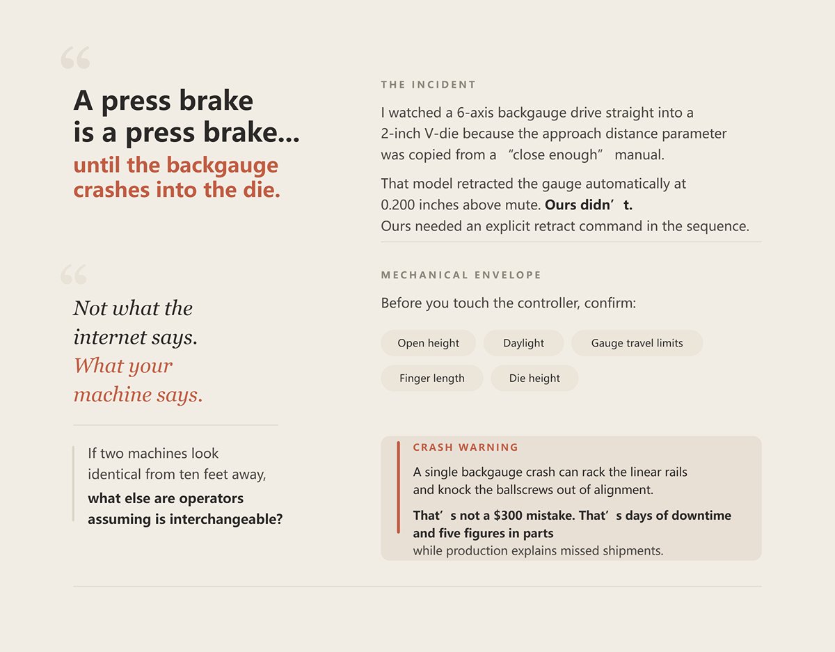
I watched a 6-axis backgauge drive straight into a 2-inch V-die because the approach distance parameter was copied from a “close enough” manual. That model retracted the gauge automatically at 0.200 inches above mute. Ours didn’t. Ours needed an explicit retract command in the sequence.
Before you touch the controller, you confirm the mechanical envelope: open height, daylight, gauge travel limits, finger length, die height. Not what the internet says. What your machine says.
Crash Warning: A single backgauge crash can rack the linear rails and knock the ballscrews out of alignment. That’s not a $300 mistake. That’s days of downtime and five figures in parts while production explains missed shipments.
If two machines look identical from ten feet away, what else are operators assuming is interchangeable?
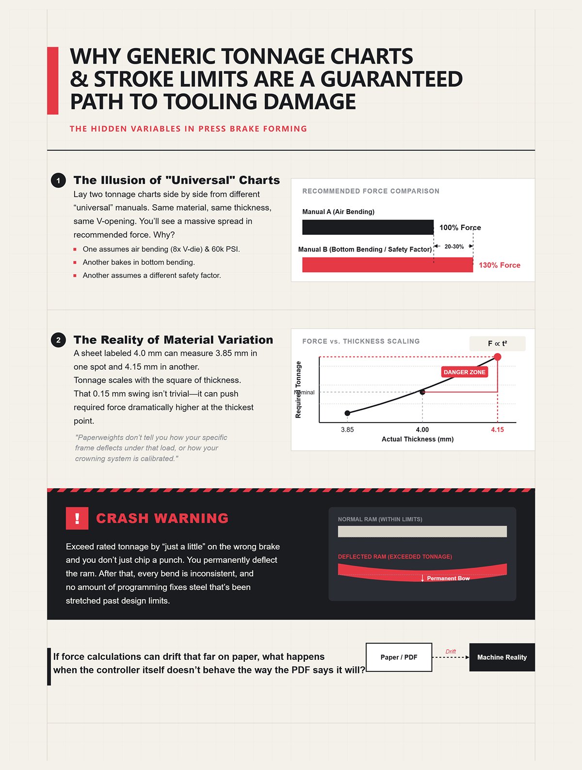
Lay two tonnage charts side by side from different “universal” manuals. Same material, same thickness, same V-opening. You’ll see 20–30% spread in recommended force. Why? One assumes air bending with an 8x V-die rule and 60,000 PSI mild steel. Another bakes in bottom bending. Another assumes a different safety factor.
Now add reality. A sheet labeled 4.0 mm can measure 3.85 in one spot and 4.15 in another. Tonnage scales with the square of thickness. That 0.15 mm swing isn’t trivial—it can push required force dramatically higher at the thickest point. The conservative move is to measure multiple points and use the maximum value. Generic charts will tell you that. Paperweights don’t tell you how your specific frame deflects under that load, or how your crowning system is calibrated.
Crash Warning: Exceed rated tonnage by “just a little” on the wrong brake and you don’t just chip a punch. You permanently deflect the ram. After that, every bend is inconsistent, and no amount of programming fixes steel that’s been stretched past design limits.
If force calculations can drift that far on paper, what happens when the controller itself doesn’t behave the way the PDF says it will?
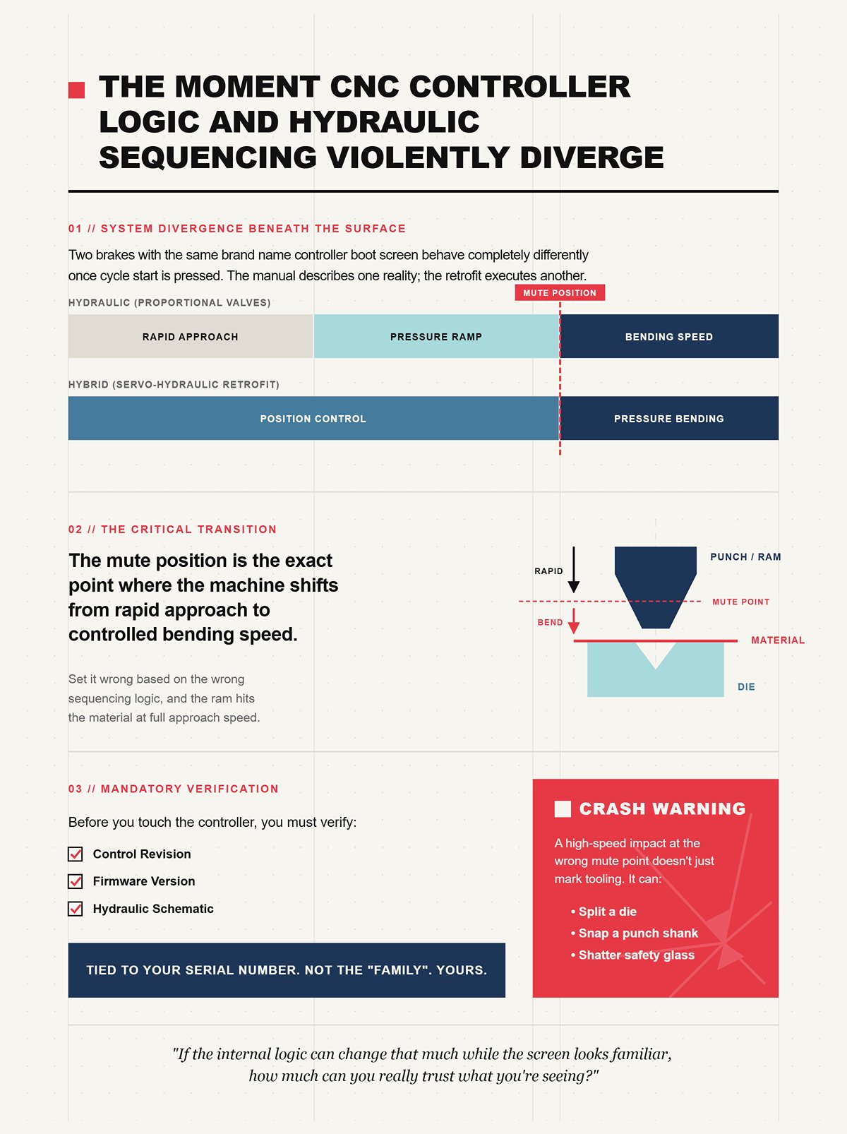
I’ve seen two brakes with the same brand name controller boot screen behave completely differently once cycle start is pressed. One was hydraulic with proportional valves. The other was a hybrid servo-hydraulic retrofit. The generic manual described a pressure ramp during approach. The retrofit used position control until mute, then switched to pressure.
That difference matters when you’re setting mute position—the point where the machine transitions from rapid approach to bending speed. Set it wrong based on the wrong sequencing logic, and the ram hits material at full approach speed.
Before you touch the controller, you verify the control revision, firmware, and hydraulic schematic tied to your serial number. Not the “family” of machines. Yours.
Crash Warning: A high-speed impact at the wrong mute point doesn’t just mark tooling. It can split a die or snap a punch shank. I’ve seen fragments hit the safety glass hard enough to spider it.
If the internal logic can change that much while the screen looks familiar, how much can you really trust what you’re seeing?
Operators trust what they recognize. Same soft keys. Same menu tree. Same parameter names.
But one revision might define bottom dead center from the encoder’s mechanical zero. Another defines it from a software offset after homing. The screen still says “BDC.” The number still changes when you jog. Underneath, the math that decides where the ram stops is different.
That’s how you end up with a program that ran safely on one machine burying a punch into a die on another—because the zero reference shifted by a millimeter and nobody realized the homing routine changed between revisions.
A generic press brake manual PDF doesn’t feel dangerous. It feels helpful. That’s the problem. It gives just enough truth to make you confident and just enough mismatch to make you wrong.
By the time most operators realize that, the crash has already happened.
You want to know how to prove the manual in your hand actually belongs to the iron in front of you.
Start with the nameplate bolted to the frame. Not the sales brochure. Not the sticker on the controller bezel. The stamped plate on the machine body that lists model, serial number, voltage, and year. That serial number is the machine’s fingerprint; everything else is a family resemblance.
If the serial on the frame doesn’t match the documentation, you are guessing.
And guessing is how backgauges get rebuilt.
Before you touch the controller, write down three things exactly as the machine states them: full model designation, serial number, and controller make and version from the boot screen. Then call the manufacturer or distributor and ask for documentation tied to that serial — not “that model,” not “that series,” that number. If they send a PDF, the first page should reference your serial or at least your production batch range. If it doesn’t, you push back.
Crash Warning: I’ve seen a shop assume a “same model” manual covered their machine, miss a 1-inch difference in open height spec, and drive a tall die set straight into the ram housing. They shear clean off like cheap bolts when you over-travel hardened steel against cast iron.
So which of those numbers actually dictates how you set the machine up?
The model number tells you the class of machine.
The serial number tells you the exact build.
The controller type tells you how it thinks.
That last one is where most people get blindsided. An NC brake might control only X (backgauge) and a single Y depth. A CNC brake might control Y1, Y2, X, R, Z1, Z2, plus crowning. Same paint. Completely different calibration logic. A generic “NC press brake” manual won’t explain how to synchronize dual Y axes with linear encoders because NC machines often use mechanical torsion bars for forced synchronization. Different architecture, different failure modes, different setup steps.
And it gets tighter. CNC machines with 13:1 or 15:1 cylinder ratios descend faster than older 6:1 or 8:1 designs. That changes approach speed, mute timing, and how much reaction time you have if something’s wrong. Those specs are not trivia. They decide whether your mute position is conservative or catastrophic.
Before you touch the controller, confirm: Is this nut-stop hydraulic or synchro hydraulic? Is synchronization mechanical or valve-controlled with encoder feedback? Those answers dictate which sections of the OEM documentation even apply to you.
Crash Warning: Calibrate Y1/Y2 parallelism using a CNC encoder procedure on a torsion-bar machine and you won’t “dial it in.” You’ll twist the bar out of spec and chase taper bends for months while scrap piles up.
If the model and controller can diverge that much, what happens when the machine isn’t even in its original configuration?
This is where paperweights really earn their nickname.
A machine can leave the factory as NC with mechanical synchronization, then get retrofitted ten years later with a CNC controller and proportional valves. The serial number on the frame doesn’t change. The soul of the machine does.
Now your “original OEM manual” explains mechanical stops and manual depth setting with a protractor, while the machine in front of you expects electronic homing and encoder zeroing. Or the reverse — a downgraded control on a frame designed for closed-loop feedback. The PDF isn’t just incomplete. It’s actively misleading.
Before you touch the controller, physically verify what’s installed: look for linear encoders on the ram sides, identify the valve block type, check whether there’s a torsion bar running across the back. Don’t assume. Inspect.
Crash Warning: I watched a shop trust the original CNC documentation on a brake that had been partially stripped back to mechanical sync after a valve failure. They attempted electronic Y-axis calibration on a system that no longer had active feedback. The result was a ram that bottomed unevenly and cracked a segmented die set on the first full-tonnage hit.
Used iron carries history. You have to read it in steel, not in PDFs.
So what do you do when the manufacturer won’t cooperate and the distributor shrugs?
Here’s how you stop getting brushed off.
You stop asking for “the manual.”
You request documentation tied to your serial number including: hydraulic schematic revision, electrical schematic revision, controller firmware compatibility list, and mechanical specification sheet listing cylinder ratio and rated open height. Specific documents with specific names. When you ask precisely, it signals you know what you’re talking about.
If they claim the generic manual covers your unit, ask them to confirm in writing that the cylinder ratio, synchronization method, and axis configuration for your serial match the PDF. Most won’t gamble on that unless it’s true.
Before you touch the controller, take photos of the nameplate, controller boot screen, valve block, and ram sides, and attach them to your request. You are removing their wiggle room. You are saying: this is the machine; send me the documents that describe this machine.
Crash Warning: Running a brake with mismatched firmware and parameter tables because “it’s close” can corrupt axis limits. When the backgauge overtravels and slams the end of its rails, you’re not arguing with tech support — you’re pricing new ballscrews.
Paperweights don’t tell you how your specific frame deflects under that load, or how your crowning system is calibrated. The exact OEM documentation does — if you force it into your hands.
Once you have it, the real work starts.
Because a correct PDF sitting unopened on a desktop is just another paperweight, and the next question is how to translate those serial-specific specs into a setup sequence that keeps steel bending instead of breaking.
You’ve got the right manual now — serial number matches the nameplate, controller firmware matches the boot screen, hydraulics match what’s bolted to the frame.
Good.
Now you stop treating it like reading material and start treating it like a checklist that stands between you and a bent ram.
I’ve watched operators download the correct OEM PDF and then set the machine the same way they “always do.” Oil looks fine. Gauges look fine. Jog it down, see what happens. That’s how you turn accurate documentation into another paperweight. The whole point of tying the manual to your serial number was to remove guessing. So the question becomes: how do you turn those specs into physical verification before steel ever meets tooling?
On one 175-ton machine we brought in, the plate on the reservoir called for ISO 46 hydraulic oil. The generic manual the previous shop had been using listed ISO 32. Close enough, they thought. It wasn’t.
ISO 32 flows thinner at operating temperature. On that machine — 15:1 cylinder ratio, fast approach — the valves were tuned for the viscosity curve of ISO 46. With 32 in the tank, the ram descended faster during approach and overshot the deceleration point. The mute timing didn’t change. The oil did. That’s how you get a die kiss you never programmed.
Before you touch the controller, open your serial-specific manual and confirm three things against the metal in front of you:
Then put a calibrated gauge on the test port and verify the relief setting matches the spec sheet. Don’t trust the panel display. “What your machine says” on the screen is software. Relief pressure is physics.
Crash Warning: Run a machine set for 3,000 psi at 3,300 because “it bends fine,” and you won’t see the damage immediately. You’ll stretch tie rods and over-stress seals until one morning the ram drops unevenly and twists a $6,000 segmented die set. They shear clean off like cheap bolts when side-loaded.
Oil viscosity affects valve response. Valve response affects ram control. Ram control determines whether your programmed depth is real or theoretical. So once hydraulics are verified, what keeps the ram from traveling farther than the steel can forgive?
I once measured a machine that showed identical Y1 and Y2 positions on the controller — dead even to three decimal places. On the part, we had a 0.5-degree taper across eight feet. The numbers agreed. The steel did not.
Here’s why.
Your serial-specific documentation lists:
Before you touch the controller, jog the ram down in setup mode and physically verify bottom dead center against the mechanical reference described in your manual. On a torsion-bar machine, that may mean confirming stop bolt contact. On a closed-loop system, it means confirming encoder zero after a proper homing cycle — the exact one your controller requires, not the one you remember from another brand.
Then you map usable stroke. Not just “it goes down 8 inches.” You confirm where tooling height plus material thickness places the bend relative to maximum rated stroke and daylight. If your manual lists 18 inches open height and you install a tall die stack that consumes 17.5, you have no forgiveness for deflection or mis-set mute.
And don’t ignore geometry. Parallelism is not a single-point check. Measure ram-to-bed distance at center and near both ends at a light contact position. If your documentation specifies a tolerance — many do in the 0.05–0.10 mm range across the length — you verify it before production tonnage. A controller reading of Y = 0.000 means nothing if one side is mechanically lagging.
Crash Warning: Set stroke depth by “sneaking up on it” with a tall die and no confirmed bottom reference, and the first full-tonnage hit can drive the punch shoulder into the die radius. You won’t chip it. You’ll crater it.
So your Y depth is real. Your limits are known. The ram stops where the manual says it should. Now the part still has to land in the same place every cycle, which brings us to the backgauge.
A shop called me about a consistent 2 mm flange error. Same program. Same material. Same operator. They had zeroed the backgauge per the controller’s generic homing routine. X-axis read 0.000 at the reference plate.
Problem was mechanical, not digital.
On that machine, each stop finger could be micro-adjusted with a screw. One finger was 2 mm out of alignment even though the carriage was square. The controller zeroed the carriage, not the fingers. The manual tied to that serial number described individual finger calibration. The generic controller book did not.
Before you touch the controller, confirm whether your machine uses:
Each architecture has a different zeroing sequence. On some systems, you must lock the backgauge STOP circuit before making rear mechanical adjustments. On others, homing must occur with the ram fully up to avoid collision with tall tooling. Your serial-specific documentation spells that out because interlocks differ by build.
And if you’re running a manual backgauge — still common for small batches — OEM pin configuration matters. Some are designed to be pushed into position; others are retained differently. Pull the wrong style under load and the part shifts mid-cycle. The machine didn’t “lose zero.” You misunderstood the hardware.
Crash Warning: Trust electronic zero alone on a machine with adjustable stop fingers and you’ll chase dimensional errors until someone overcompensates by deepening the bend. That’s when the punch bottoms in the die and you hear the crack.
The backgauge defines part location. The ram defines bend angle. The tooling defines how force transfers between them. Which is where most expensive mistakes hide.
I’ve seen a 12-foot European-style punch sitting proud by less than a millimeter because debris sat under the tang. Looked seated. Wasn’t.
Under load, that tiny gap closed violently. The punch shifted laterally and marked every part in the batch.
Your serial-specific manual will state the clamping style:
Before you touch the controller, clean the clamping surfaces and verify seating per the OEM procedure. European systems require full tang engagement across the length. American systems demand even bolt torque to prevent localized lift. If hydraulic clamping is used, confirm clamping pressure matches the spec — not just that the light is green.
Tool height matters too. Your open height and stroke mapping from Step 2 only protect you if the installed punch and die match the assumed heights in your setup sheet. A 1-inch taller die than programmed effectively erases 1 inch of daylight. That’s how tall die sets get driven into ram housings.
Crash Warning: Mix American and European tooling without proper adapters because “it fits,” and you’ll side-load the clamp. Under 100 tons, that misfit doesn’t bend — it ejects.
At this point, hydraulics are verified, Y limits are mapped, the backgauge is mechanically honest, and the tooling is truly seated — not assumed to be.
Now the machine is ready to bend.
And the next question isn’t about today’s setup. It’s about what happens after 10,000 cycles, when wear, heat, and drift start nudging those same verified numbers out of spec.
| Step | Title | Key Checks & Actions | Critical Specifications to Verify | Crash Warning / Risk |
|---|---|---|---|---|
| Step 1 | Verifying hydraulic oil type, level, and pressure specs before startup | Confirm oil type per serial-specific manual; check reservoir capacity and sight-glass range; verify system pressure with calibrated gauge at test port | Exact ISO oil grade (e.g., ISO 46 vs ISO 32); reservoir capacity and proper level range; maximum relief pressure; working forming pressure | Incorrect oil viscosity alters valve response and ram speed, causing overshoot and die damage; excessive pressure (e.g., 3,300 psi vs 3,000 psi) can stretch tie rods, overstress seals, and cause uneven ram drop leading to tooling failure |
| Step 2 | Mapping Y-axis limits and setting stroke depth | Verify bottom dead center against mechanical reference; perform proper homing cycle; measure ram-to-bed parallelism at multiple points; map usable stroke considering tooling height and material thickness | Maximum open height; maximum stroke; mechanical stop or encoder zero reference; synchronization method (torsion bar or closed-loop); parallelism tolerance (e.g., 0.05–0.10 mm) | Incorrect stroke mapping or parallelism can drive punch shoulder into die radius, causing cratering or severe tooling damage |
| Step 3 | Controller-specific backgauge reference and zeroing | Identify backgauge architecture (X, R, Z1/Z2, or manual); verify individual stop finger alignment; follow serial-specific zeroing sequence; ensure proper mechanical adjustments before homing | Axis configuration; finger calibration method; STOP circuit requirements; homing position requirements (e.g., ram fully up) | Misaligned stop fingers or improper zeroing leads to dimensional errors; overcompensation by deepening bend can cause punch bottoming and cracking |
| Step 4 | Tooling seating procedures (European vs. American clamping) | Clean clamping surfaces; verify full seating per OEM method; confirm clamp pressure or bolt torque; ensure tooling height matches setup assumptions | Clamping style (European/Promecam, American, hydraulic/mechanical crowning); clamping pressure; bolt torque; punch and die height | Improperly seated or mismatched tooling can shift under load, mark parts, side-load clamps, or eject tooling under high tonnage |
Ten thousand cycles into a production run, the parts still look “pretty good.” Angle is drifting half a degree. Flanges vary a millimeter across a 10-foot blank. The operator tweaks depth another 0.2 mm and keeps going.
That’s how drift sneaks in — not with a bang, but with a nudge.
You verified everything on day one. Y limits were real. Backgauge was mechanically honest. Tooling was seated. Now heat has thinned the oil, seals have worn in, and the frame has flexed under load thousands of times. The baseline you established is only as good as your plan to protect it. And that plan lives in the documentation tied to your serial number — not in a generic PDF that makes nice paperweights.
Because maintenance isn’t about checking boxes. It’s about preventing calibrated truth from quietly decaying into expensive fiction.
I walked into a shop running a 175-ton brake on ISO 46 oil because the generic chart said “typically ISO VG 46.” The pump whined on cold mornings. Pressure lagged on rapid approach. They were changing oil every 2,500 hours like clockwork.
Problem was, that specific build left the factory spec’d for ISO 32 due to tighter valve clearances and a different ambient temperature range. Thicker oil on cold start means higher suction resistance at the pump inlet. Higher suction resistance means cavitation — microscopic vapor bubbles collapsing against metal surfaces. They shear clean off like cheap bolts. You don’t see it immediately. You hear it as a faint growl.
Now add “standard” 500-hour hydraulic checks. On some machines, 500 hours is fine. On others with smaller reservoirs and higher duty cycles, oil temperature spikes faster, oxidation accelerates, and varnish forms on servo valves. A generic interval assumes average load, average environment, average duty cycle. Your pump doesn’t live in average.
Crash Warning: Run the wrong viscosity for your specific valve block and ignore the OEM’s shorter filter interval, and you won’t just lose pressure stability — you’ll score the pump housing. That’s a five-figure repair and weeks of downtime because someone trusted “typically.”
So when the manual says 2,000–3,000 hours, that range is not permission. It’s a boundary. Your serial-specific service notes tell you where inside that boundary your machine survives.
And hydraulics are only half the story. What about the metal sliding on metal every cycle?
On one model we ran, there were eight grease points along the ram gib system — two of them tucked behind removable covers near the left upright. Miss those, and the ram wore unevenly on that side. Took about six months before anyone noticed the left flange angles were consistently off on long parts.
The generic manual said, “Lubricate ram guides weekly.” Helpful. Where, exactly?
Model-specific documentation shows you the actual map: gib screws, backgauge linear rails, crowning screws in the bed. Some designs have mechanical crowning bars with exposed adjustment screws that need inspection and lubrication. Others are hydraulic and sealed. If you grease a sealed system because you saw it in another manual, you contaminate it. If you skip exposed screws because your PDF doesn’t mention them, they corrode and bind.
Before you touch the controller, you should know where friction is designed to exist and where it isn’t. That’s not universal. That’s engineered per frame.
I’ve seen backgauge rails wiped daily on one machine because fine stainless dust would score the linear bearings. Another model had protective bellows and didn’t require that frequency. Same brand. Different build.
Crash Warning: Ignore a hidden lubrication point on a long-bed machine and the ram starts tracking out of parallel under load. Keep compensating with Y-depth, and one day you’ll side-load a punch hard enough to chip it across three stations.
And that brings us to the quiet killer of accuracy — parallelism drift.
A refurbished press brake can perform nearly like new — I’ve seen hydraulic leakage variance under a couple percent when properly rebuilt. The iron is stable if you respect it.
But stability doesn’t mean self-correcting.
I had a machine showing a consistent 0.7-degree difference between left and right ends on a 3-meter bend. Operator kept adjusting depth globally. That just moved the problem around. The controller said both Y1 and Y2 were synchronized. What your machine says is not the same as what the steel does.
The factory calibration guide for that serial number specified checking ram-to-bed distance at three positions with a dial indicator at light contact, tolerance 0.05 mm across length. It also detailed the mechanical adjustment sequence — which side to correct first to avoid chasing error across the stroke.
A generic controller manual will tell you how to zero encoders. It will not tell you the mechanical bias built into that frame, or the torque spec for the gib adjustment bolts after correction. Paperweights don’t tell you how your specific frame deflects under that load, or how your crowning system is calibrated.
Crash Warning: Skip the mechanical parallelism check and rely on electronic sync alone, and you’ll deepen one side to fix angle. Under full tonnage, that uneven load twists the ram. Twist it enough times and you’re not recalibrating — you’re replacing.
So what happens when you don’t even have the right service chart in front of you?
I once watched a young operator dismiss a faint foam line in the hydraulic sight glass. “Fluid level’s fine,” he said. Level was fine. Condition wasn’t.
Foaming can mean air ingress — loose suction fittings, degraded seals. On a model with a top-mounted return line, that foam tells you something different than on a bottom-return design. Without the service chart, you don’t know whether that pattern is normal turbulence or a warning.
Oil darkening? On one machine, slight amber shift was expected at 1,000 hours due to higher operating temps. On another with a larger reservoir and cooler, darkening that early meant overheating. Same symptom. Different implication.
Modern CNC brakes will flash maintenance reminders on the control. Filter hours. Pump runtime. Temperature thresholds. That’s not decoration. That’s embedded OEM knowledge talking back to you. If your generic PDF says “inspect annually” but the control flags a pressure filter differential alarm at 1,200 hours, you follow the machine.
Before you touch the controller, look at the metal and the oil. Listen to the pump on cold start. Watch for delayed pressure build. Check for asymmetrical cylinder rod sheen — one polished more than the other can hint at load imbalance.
Crash Warning: Ignore rising oil temperature because the generic schedule says you’re “not due yet,” and you’ll cook seals. Once a cylinder starts bypassing internally, angle consistency disappears and you won’t know why until parts are scrap.
Documentation sets the baseline. Your senses confirm the trend. But there’s a point where reading signs isn’t enough — where drift, alarms, or mechanical correction cross into territory that only the builder can resolve.
And that’s where the manual stops being guidance and becomes a boundary.
You want a clean line. A point where you stop wrenching and pick up the phone.
Here it is: the moment you move from verifying condition to changing behavior.
Lubrication, alignment checks, filter swaps — that’s condition management. You’re preserving what the factory engineered. But the second you consider altering proportional valve bias, servo gain, pressure limits, or hidden system parameters, you’re rewriting how the machine thinks and reacts under load. That’s not maintenance. That’s surgery.
I’ve seen the most expensive crashes start with, “It’s just a small parameter tweak.”
Even with the exact OEM manual for your serial number, there are sections that exist to define boundaries, not to invite experimentation. Some procedures assume factory gauges, proprietary software access levels, or calibration rigs you don’t have. The manual tells you the sequence. It does not give you the feel of a seasoned field tech who knows how that specific frame behaves when it’s warm, or how that generation of valve sticks when corrosion starts in the spool bore.
The non-obvious part? The correct manual doesn’t make you qualified. It tells you where the cliff edge is.
So where is that edge, exactly?
A proportional valve meters hydraulic flow based on command signal. In a press brake, that means it governs how pressure builds and balances between cylinders. Change its bias or gain, and you change how force arrives at the tooling.
On paper, adjusting it can look like a tidy fix for parallelism drift or pressure imbalance. The spec might list a target voltage or current range at a given pressure. Looks measurable. Looks manageable.
But proportional valves fail in ways that masquerade as other problems. Corrosion in the spool. Debris partially blocking an orifice. Air trapped in the hydraulic circuit creating compressibility you can’t see. You can follow the manual exactly, hit the electrical targets, and still have a mechanical restriction inside the valve body.
So you compensate.
You bump the setting to “correct” the lag. Pressure rises unevenly. The slow side catches up — until full tonnage, when the blocked side suddenly frees and spikes.
Crash Warning: Guess at proportional valve compensation and you can drive one cylinder ahead under load, twist the ram, and chip a segmented punch across multiple stations. They shear clean off like cheap bolts.
Here’s the hard limit: if the adjustment involves altering factory-set proportional valve parameters beyond documented inspection tolerances — stop. If the fix requires interpreting behavior under dynamic load rather than static measurement — stop. That’s when you call the manufacturer or a certified hydraulic tech with the right test equipment.
Because the question isn’t “Can I turn this screw?” It’s “Do I know what else changed that I can’t see?”
And that leads straight into controller parameters.
Before you touch the controller, you document everything. Not the big obvious numbers. Everything.
Y1/Y2 gains. Pressure setpoints. Crowning offsets. Acceleration ramps. Any hidden service-level parameters your access allows. You create a snapshot — photos, exports, handwritten logs if you have to.
Why?
Because hardware degrades silently. Clogged hydraulic passages can reduce effective pressure over time. Air in the system can create a bounce that feels like overshoot. A proportional valve only fully reacts past a certain pressure threshold — meaning light test bends won’t even trigger the condition you’re chasing.
If you change controller gains to “smooth out” motion without knowing whether the root cause is electrical tuning or hydraulic restriction, you’re building correction on top of decay.
Crash Warning: Adjust servo gain to mask a sticky valve, and the next panic-depth correction at full tonnage can overshoot bottom dead center hard enough to drive a tall die into the ram housing.
Baseline documentation does one critical thing: it tells you whether the machine changed, or you did.
But here’s the line most shops miss — if restoring parameters to documented OEM baseline does not return the machine to stable, repeatable behavior, you are no longer dealing with tuning. You are dealing with component failure or structural shift. That’s not a PDF problem. That’s a manufacturer problem.
So how do you keep from reaching that edge blindly?
Most operators treat the manual like a fire extinguisher. Break glass when something smells hot.
That’s backward.
Your serial-specific manual should live beside the machine as a working log. Not just lubrication intervals, but recorded oil temperature trends. Pressure readings at known tonnage. Parallelism checks at defined intervals. Notes after any unrelated repair — pump replacement, seal change, even moving the machine.
Because here’s what paperweights don’t tell you how your specific frame deflects under that load, or how your crowning system is calibrated — but your own historical data will.
Hydraulic systems age. Orifices clog gradually. Seals harden. A baseline taken today may not behave the same in six months under identical settings. If you log trend data, you see drift early. If you don’t, the first sign is scrap or a bang.
And here’s the non-obvious threshold: when your logged trends show deviation beyond OEM tolerance, and restoring documented specs does not stabilize the curve, you close the PDF.
Not because you failed.
Because you’ve reached the design boundary of what in-house maintenance can safely influence.
That’s the one thing I want you to carry forward: the manual is a map of the machine’s intended behavior, not a license to redefine it. The moment you step from preserving factory intent into altering system dynamics under load, you’re no longer maintaining — you’re engineering.
And unless you built the aircraft, you don’t rewrite the flight manual midair.


