

The program ran clean. No red collision highlights. Nice smooth animation of the ram coming down, flange clearing the tooling, backgauge fingers sliding out of the way like choreography.
First part on the real brake? The return flange kissed the backgauge housing and stalled the cycle halfway down.
Nothing was “wrong” in the software. That’s the problem.
Most shops buy simulation to see the bend before they cut steel. Fair. A moving 3D model feels like control. But motion on a screen isn’t the same thing as motion constrained by 60 tons of steel, servo lag, worn tooling, and a backgauge that’s been nudged out of square three times this year.
An arcade flight game looks like flying. A certified simulator models every control surface, weight shift, and stall behavior. One entertains. The other trains pilots who expect consequences.
Press brake software is no different.
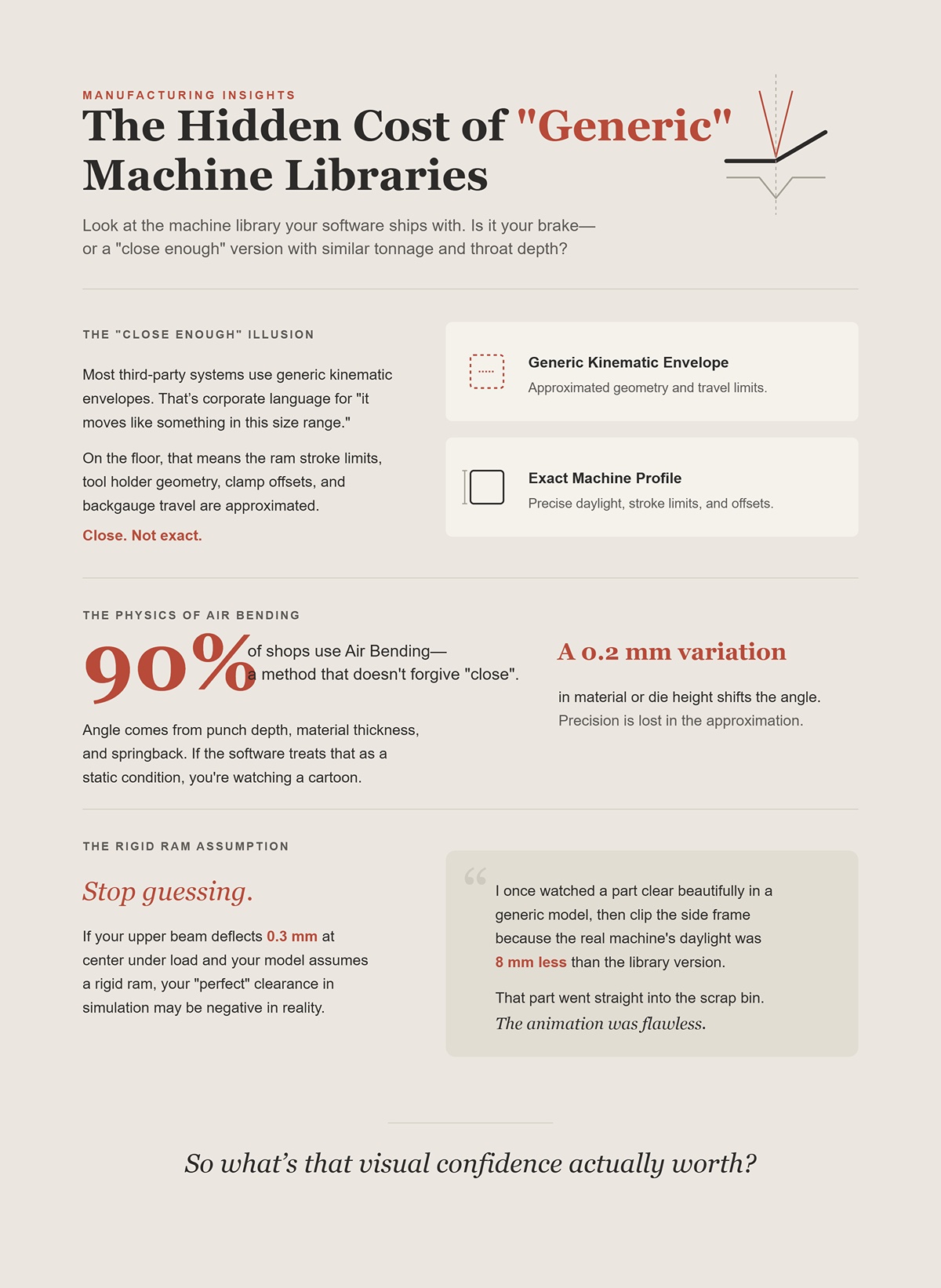
Look at the machine library your software ships with. Is it your brake—or a “close enough” version with similar tonnage and throat depth?
Most third-party systems use generic kinematic envelopes. That’s corporate language for “it moves like something in this size range.” On the floor, that means the ram stroke limits, tool holder geometry, clamp offsets, and backgauge travel are approximated. Close. Not exact.
Air bending—the method 90% of shops use—doesn’t forgive “close.” Angle comes from punch depth, material thickness, and springback. A 0.2 mm variation in material or die height shifts the angle. If the software treats that as a static, ideal condition, you’re watching a cartoon version of your process.
Stop guessing. If your upper beam deflects 0.3 mm at center under load and your model assumes a rigid ram, your “perfect” clearance in simulation may be negative in reality.
I once watched a part clear beautifully in a generic model, then clip the side frame because the real machine’s daylight was 8 mm less than the library version. That part went straight into the scrap bin. The animation was flawless.
So what’s that visual confidence actually worth?
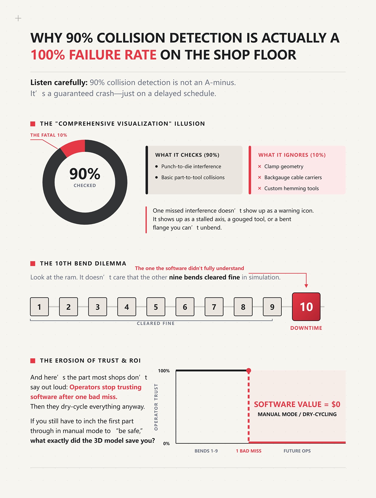
Listen carefully: 90% collision detection is not an A-minus. It’s a guaranteed crash—just on a delayed schedule.
If your software checks punch-to-die interference and basic part-to-tool collisions but ignores clamp geometry, backgauge cable carriers, or custom hemming tools, you’re running partial protection. Corporate brochures call this “comprehensive visualization.” On the floor, it means “we didn’t model that piece.”
One missed interference doesn’t show up as a warning icon. It shows up as a stalled axis, a gouged tool, or a bent flange you can’t unbend.
Look at the ram. It doesn’t care that the other nine bends cleared fine in simulation. The tenth bend—the one the software didn’t fully understand—decides your downtime.
And here’s the part most shops don’t say out loud: operators stop trusting software after one bad miss. Then they dry-cycle everything anyway. If you still have to inch the first part through in manual mode to “be safe,” what exactly did the 3D model save you?
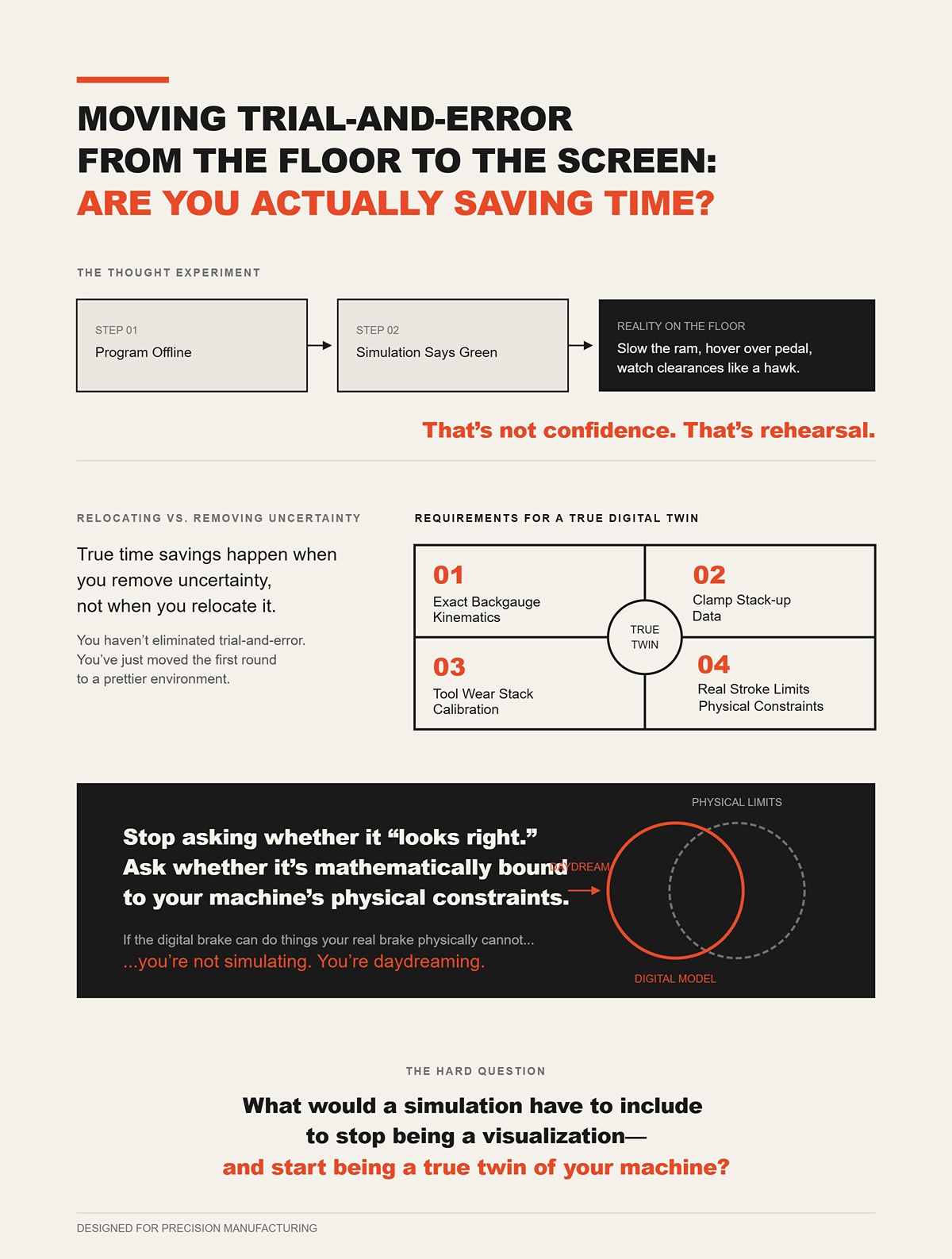
Run the thought experiment. You program offline. The simulation says green light. On the floor, you still slow the ram, hover over the foot pedal, and watch clearances like a hawk.
That’s not confidence. That’s rehearsal.
True time savings happen when you remove uncertainty, not when you relocate it. If your model doesn’t replicate your exact backgauge kinematics, clamp stack-up, tool wear stack, and real stroke limits, you haven’t eliminated trial-and-error. You’ve just moved the first round to a prettier environment.
Stop asking whether it “looks right.” Ask whether it’s mathematically bound to your machine’s physical constraints.
Because if the digital brake can do things your real brake physically cannot, you’re not simulating. You’re daydreaming.
And that raises the harder question: what would a simulation have to include to stop being a visualization—and start being a true twin of your machine?
Picture a 3‑meter panel, 6 mm mild steel, four bends in. The screen shows daylight to spare, clean rotation, no red highlights. On the floor, the fifth bend stalls because the upper clamp body—never modeled—occupies the same space your return flange now wants. The program ran clean. The brake did not.
That’s the gap we’re closing here.
If a digital twin is going to earn that name, it has to replicate every physical constraint that can stop motion: real tool geometry, real backgauge travel, real deflection under load, real stroke limits. Not “similar.” Not “machine class.” Your machine. A twin that ignores your stroke ceiling and deflection curve isn’t a twin — it’s a distant cousin who’s never set foot in your shop.
And once you accept that, the question stops being “does it look right?” and becomes “what exactly must be modeled so it physically cannot lie to me?”
Start with the tooling cabinet, not the CAD file.
I’ve seen shops proudly import a perfect DXF, only to discover their simulation used a “standard 88-degree punch” that existed nowhere in their rack. The real punch had a relieved shoulder. The clamp stack added 42 mm of height. The holders had asymmetric ears. None of that lived in the model.
Stop guessing. If your tool library doesn’t include exact punch tip radius, shoulder profile, holder body, clamp type, and total stack height, you are not simulating a brake—you’re animating a bend concept.
Here’s the mechanism: collision detection engines work on geometry. If the geometry is simplified—say the punch is modeled as an infinitely thin wedge—then the software can only detect interference against that fiction. Even sophisticated systems using bounding hierarchies (that’s programmer talk for “fast 3D hit-testing”) still miss manufacturability problems when the underlying tool shapes are wrong. A non-planar profile might look feasible in a generic 3D viewer yet be impossible on a press brake because the holder body blocks rotation long before the punch tip does.
And tooling wear matters. I’ve measured dies 0.15 mm different in height across stations after years of service. Angle drift followed the taller shoulder. If your library assumes every die is factory-fresh and perfectly matched, the model is already lying about penetration depth and angle.
Years ago I trusted a “close enough” tool model on a rush job. First part down, the real clamp ear tagged the return leg. Tiny mark. Customer saw it. That entire batch fed the scrap bin because the cosmetic spec was tight.
So when a vendor says “integrated tool management,” translate it to shop-floor terms: are you modeling the exact steel bolted to my ram today—including its warts—or just a catalog drawing?
Look at the backgauge carriage, not just the fingers.
Most simulations map X and R travel limits and call it done. That’s like modeling a truck by its wheelbase and ignoring the cab. On the floor, the housing, linear rails, cable carriers, and even bolt heads define your real envelope.
Stop assuming the gauge is a point in space. It’s a moving assembly with width, height, and depth.
The expensive misses happen during part rotation. The software checks the flange against the finger tip but ignores the carriage body 80 mm behind it. The bend clears in the animation. In reality, the flange sweeps a wide arc and smacks the carriage side plate halfway through rotation.
Mechanically, this is simple geometry: rotation radius equals flange length plus material thickness plus any offset from the bend line. If that radius exceeds the clearance to the nearest solid mass—finger bracket, housing, frame—you collide. If the model only includes the finger tip, it cannot detect that sweep.
I once watched a 1.5-meter channel rotate beautifully on screen. On the brake, the second leg caught the cable track that feeds the Y2 axis. Not even the gauge itself—the cable track. The repair cost more than the software seat.
Corporate brochures call this “backgauge interference detection.” On the floor, that should mean: every solid body behind the fingers is mapped in 3D and constrained to its true axis travel. Anything less is partial vision.
And if your shop runs mixed fleets, here’s the uncomfortable truth: inference systems that monitor electrical load and axis motion can tell you uptime trends without modeling any of this geometry. That’s fine for maintenance dashboards. But they cannot tell you whether a 600 mm return flange will clear the R-axis housing on machine #3. Different jobs. Different physics.
So when someone claims “machine-agnostic compatibility,” ask yourself: do I want a fleet report—or do I want to know if this part will physically rotate?
Clamp a 3-meter, 4 mm stainless sheet and run 70% of machine tonnage. Watch the ram and bed under load. You won’t see it with your eye, but measure center penetration versus ends and you’ll find variation. I’ve recorded around 0.3 mm center deflection on older hydraulics under heavy load.
If the model treats the ram and bed as perfectly rigid beams, every simulated bend along that length assumes uniform penetration. That’s fantasy.
Stop pretending steel doesn’t flex.
Crowning systems—manual wedges or CNC-controlled—exist because the machine bends in the middle under load. If your simulation doesn’t include your machine’s deflection curve and the behavior of its crowning system, it can predict clearance and still miss angle uniformity across the part.
The mechanism is straightforward: angle in air bending is a function of punch depth relative to die opening. If center deflection reduces effective penetration by even 0.1–0.2 mm, angle opens up. On long parts, that compounds over multiple bends, and your final geometry walks.
Servo-electric machines add another layer. Their ball-screw drives can repeat ram position within microns because there’s no hydraulic oil “breathing” with temperature. But that precision only matters if the simulation reflects servo-specific motion profiles and limits. Modeling every brake as a generic hydraulic slider ignores how acceleration, deceleration, and stroke control differ between platforms.
If the software treats that as a static, ideal condition, you’re watching a cartoon version of your process.
I’ve chased a long-part angle issue for half a shift before realizing the model had zero deflection logic. The part bowed just enough that the final flange wouldn’t sit flat in assembly. We re-bent. It cracked. Another batch leaning against the wall.
So ask: does the simulation know how your specific frame bends—and how your crowning corrects it—or is it assuming a machine that exists only in a brochure?
Look at the ram stroke chart in your manual.
Every brake has hard limits: maximum daylight, minimum shut height, Y-axis stroke ceiling, safe approach speeds, deceleration zones. Yet many software libraries define motion as “ram moves down until contact,” full stop.
Stop accepting “similar tonnage” as machine identity.
On one install I reviewed, the digital model allowed 15 mm more open height than the real brake. In simulation, a tall box cleared easily during rotation. On the floor, the part hit the side frame because the real daylight was tighter and the ram couldn’t retract high enough to give rotation space.
That’s pure kinematics: if the maximum Z retraction is less than the part’s required rotation envelope, the move is physically impossible. A generic model that extends stroke beyond reality creates motions your brake cannot execute.
Hydraulic machines add variability. Oil temperature changes effective positioning during long runs. Servo machines don’t drift the same way but have different torque and speed characteristics near stroke limits. If 73% of shops still run legacy hydraulics, then a “one-ram-fits-all” model erases the very behavior most shops live with daily.
Years back, I trusted a generic stroke limit during a deep box program. Simulation said retract, rotate, continue. Real machine hit its upper limit and stopped mid-cycle. The operator forced a workaround. The punch kissed the die shoulder. Tooling crash. Expensive lesson in what “close enough” means at 80 tons.
A true digital twin constrains motion exactly the way your brake does—same stroke ceiling, same shut height, same decel behavior, same axis limits. If the virtual ram can travel where your physical ram cannot, you are not simulating production. You are rehearsing a move your machine will refuse to perform. That level of fidelity starts with the machine itself, which is why evaluating the actual platform—such as a CNC-based solution from CN-HAWE’s press brake systems—is inseparable from evaluating the software that models it.
And once you understand how high that bar really is, the next question isn’t theoretical anymore.
Which software actually clears it—and which ones are still selling arcade games with better graphics?
A few years back I stood behind a new 8‑axis brake running its own brand’s offline software. The program ran clean. No collisions on screen. Gauges moved like choreography. First part off the machine? Back flange tagged the R-axis housing because the shop had swapped to a shorter custom finger that wasn’t in the OEM library.
That’s the question in front of us now. Not who has prettier graphics. Not who has more marketing videos. Which platforms actually model your machine as it exists on your floor — and which ones assume the catalog version?
You’ve already seen how high the bar is: real stroke limits, real deflection curves, real axis envelopes. So when we compare OEM-native systems to third-party “machine-agnostic” tools, we’re really asking one thing: is this a certified flight simulator wired into your cockpit, or an arcade game that just looks like one?
Let’s separate the heavyweights.
Open a native file from an OEM suite and push it straight to the controller. No post. No translation. No middleman. The same company that wrote the control firmware wrote the offline simulator. That matters.
Because “zero-friction communication” in brochure language means this in shop terms: the NC code your controller executes is generated by the same logic tree that runs in simulation. Bend depth calculation, crowning compensation tables, deceleration zones near bottom dead center — they’re using the same math.
If your controller pauses 2 mm before theoretical depth to let its real-time angle correction system read load and adjust — the offline sim knows that behavior because it was designed around it. That’s not cosmetic. That’s kinematic alignment.
Now the trade-off.
Look at a Cincinnati retrofit from a few years back — new OEM control added to a veteran hydraulic frame. You get 3D simulation and networking, yes. But installation requires factory service, parameter migration, hardware integration. And once you’re in that ecosystem, you’re in. Tool libraries, machine models, updates — all native. All controlled.
Stop pretending that’s free flexibility.
Even in OEM environments, data friction shows up. I’ve seen bend allowance tables shift when CAD exports were interpreted differently by the controller module. DXF is “universal” in theory. In practice, K-factor assumptions still drift. If even native systems can stumble on geometry translation, the only reason they recover is because the controller and sim share the same internal language.
That shared language is the real asset. The lock-in is the price.
So what happens when the software doesn’t come from the same factory as the iron?
I once reviewed a third-party package running three different brake brands in one shop. On screen, it handled them all. Same interface. Same workflow. That’s the promise of agnostic tools: one brain for a mixed fleet.
In corporate speak, they “support multiple controller dialects.” On the floor, that means they generate generic bend instructions, then pass them through a post-processor — a translator — to convert into each controller’s native code.
If you still have to inch the first part through in manual mode to “be safe,” what exactly did the 3D model save you.
Look at the ram.
Does the third-party model include your exact Y-axis deceleration ramp near shut height? Does it know your specific controller’s safe approach speed limits when tonnage exceeds a threshold? Or is it calculating idealized depth, then trusting the post to patch differences on export?
JEELIX and similar reviews have pointed out the hard truth: generating universally accurate, optimized NC code across every brand and model is brutally difficult. Proprietary logic lives inside each controller — springback compensation routines, dynamic crowning adjustments, safety interlocks that alter motion paths.
An agnostic tool can model geometry beautifully and still mis-handle controller-specific behavior during code generation. That’s not a graphics problem. That’s a kinematic fidelity problem at the execution layer.
The upside? Flexibility. Mixed fleet? Older hydraulics next to new servo-electrics? Third-party platforms often let you centralize programming without buying three OEM ecosystems.
The risk? Every bend passes through a translator.
And every translator introduces interpretation.
Which brings us to money, because ideology doesn’t pay for scrapped stainless.
Picture a medical enclosure with ±0.2 mm tolerance on hole-to-flange location. Material: 2 mm 304 stainless. Four bends. If the first part is wrong, you don’t “tweak and ship.” You scrap.
One shop I advised ran native OEM simulation tied directly to their angle measurement system. The controller paused near final depth, measured actual angle under load, compensated on the fly. Offline sim predicted tonnage and penetration based on the same compensation tables. First piece routinely hit spec without hand-walking.
Now compare that to a hypothetical mixed-fleet shop using third-party offline programming. Simulation says 12.43 mm penetration. Post translates to controller code. Machine’s internal springback routine nudges depth differently than expected. First part comes out 0.6° open. Operator bumps depth, reruns.
That single correction might cost five minutes.
Do that across 40 precision jobs a week and you’ve eaten hours — not counting the occasional scrap when tolerance stacks across multiple bends.
Stop guessing at ROI in license dollars alone.
Native kinematics earn their keep when first-piece accuracy matters more than software flexibility. But here’s the uncomfortable counterpoint: modern controllers with real-time angle correction can sometimes eliminate first-piece scrap even without perfect offline simulation. They measure and adjust in-machine.
So you have to ask yourself: is your scrap coming from angle error under load — which smart controllers can fix — or from impossible motion paths and clearance lies — which only high-fidelity kinematics can prevent before the ram moves?
Different failure modes. Different value propositions.
And that hinges on how code actually reaches the control.
Imagine two paths.
Path one: the offline system writes code directly in the controller’s native format. No conversion. What you simulate is what runs.
Path two: the offline system generates a neutral bend description — positions, angles, sequences — then a post-processor converts it into brand-specific code.
That post is not a simple dictionary. It’s a rulebook trying to mimic proprietary behavior it doesn’t fully own.
When a controller has embedded logic — automatic crowning adjustment based on tonnage curves, adaptive bend speed changes near contact, safety-driven axis synchronization — the third-party post must either approximate that logic or defer to the machine and hope alignment holds.
If the software treats that as a static, ideal condition, you’re watching a cartoon version of your process.
I’ve seen a post miss a controller-specific dwell requirement before angle measurement. Simulation showed smooth flow. On the floor, the machine paused unexpectedly, shifting part balance mid-rotation. Minor? Yes. But stack enough “minor” mismatches and you’re back to babysitting first pieces.
So here’s the dividing line.
OEM-native systems reduce translation risk because there is no translator. Third-party systems live or die by the quality of their post-processors and how deeply they model controller logic, not just geometry.
One gives you tight integration with less flexibility. The other gives you fleet freedom with translation exposure.
Now that we’ve separated machine physics from software branding, the next promise vendors make sounds even bigger: automatic bend sequencing that “optimizes” everything for you.
But optimization only means something if the physics underneath are telling the truth.
You’ve seen the demo.
Operator loads a part. Clicks “Auto Sequence.” The software rearranges bends, avoids collisions, shows a tidy green checkmark. The rep says cycle time drops 18 percent. The program ran clean.
Now answer the real question: can that algorithm truly optimize production if the simulation underneath isn’t fully faithful to your machine’s kinematics and controller logic?
If the underlying model is lying about ram deceleration, crowning behavior, or how your controller pauses for angle measurement, then the algorithm isn’t optimizing physics. It’s rearranging assumptions. And rearranging assumptions just rearranges where the scrap shows up.
I learned that the hard way when an “optimized” sequence tucked a return flange inside early to reduce regrips. Looked brilliant on screen. On the floor, the machine’s actual safe approach speed near shut height stretched the stroke time enough that the supposed time savings vanished — and the early flange blocked gauge contact on the third bend. That part went straight into the scrap bin. Optimization without real kinematics is just confident guessing.
So when do you trust the algorithm?
If you’re not sure whether your current system is truly physics-driven or just rule-based with better marketing, it’s worth pressure-testing the stack behind it. CN-HAWE supports high-end CNC-based bending and sheet metal automation solutions, backed by dedicated R&D across press brakes and intelligent equipment to validate real machine behavior—not just theoretical sequencing. If you want to evaluate your current simulation workflow, compare kinematics fidelity, or discuss a press brake setup aligned with real production constraints, you can contact CN-HAWE here to start the conversation.
Stop guessing what kind of engine you’re actually running.
Most so-called automatic sequencing in mid-tier systems is rule-based. That means it follows heuristics: bend largest flange first, avoid trapped features, minimize tool changes, keep part stable against the backgauge. Think of it as a smart checklist.
It does not solve the dynamic motion equations of your specific machine. It assumes the machine will behave within idealized limits provided by the software.
A physics-driven optimizer, by contrast, runs motion simulation with axis limits, acceleration curves, and collision envelopes tied to your real machine configuration. It evaluates not just “Can this bend be done?” but “How long will this exact axis movement take on this brake, with this controller behavior?”
Here’s the fracture line.
If your material database is generic and your springback coefficients haven’t been calibrated with test bends, the optimizer is calculating penetration depth from theory, not your shop reality. We both know stainless from two suppliers can vary enough to swing angle by half a degree. Standard brakes might hold ±0.5° “when properly maintained.” That phrase hides a lot — worn tooling shoulders, tired hydraulic seals, uneven crowning.
If the optimizer treats that as a static, ideal condition, you’re watching a cartoon version of your process.
I once crashed tooling because a rule-based engine sequenced a deep box with a narrow window bend too early. The geometry cleared in simulation. In reality, the machine’s backgauge fingers had a slightly different mounting offset than the default library. Five millimeters of fiction. One cracked punch. The algorithm didn’t fail because it was stupid. It failed because it didn’t know my machine.
So the next question isn’t whether the sequence “works.” It’s whether the engine understands your brake as a physical system or just as a geometric shape.
Look at your ugliest part.
Not the tidy bracket from the sales brochure. I mean the asymmetrical enclosure with offset hems, mixed flange heights, and one side that has to clear a welded stud later in assembly.
Now imagine running that through automatic batch sequencing across 40 parts overnight.
The promise is seductive: let the software churn, come in to fully optimized programs. In simple families of parts — same material, same tooling, consistent geometry — that can work. The algorithm applies the same rule set, and your machine behaves predictably enough.
But asymmetry breaks patterns.
When a part has one long flexible flange and one short stiff return, the order of bends changes how the part springs and twists under load. Offline simulation rarely models elastic deformation of the partially formed part with high fidelity unless you’re in very high-end systems with heavy computation time. Most engines assume rigid bodies between bends.
That assumption matters.
I watched a batch-optimized run on thin galvanized panels where the algorithm consistently bent the long flange first to “improve stability.” On the floor, that first bend introduced a slight twist. By the third bend, backgauge contact was inconsistent. The operator compensated manually, part by part. No crash. Just creeping dimensional drift and extra handling.
Batch logic doesn’t see twist. It sees clean geometry.
That’s why complex asymmetrical work still needs a human eye before release. Not to rewrite every sequence — but to sanity-check whether the optimizer understood the part’s behavior, not just its shape.
If you still have to inch the first part through in manual mode to “be safe,” what exactly did the 3D model save you?
Demand one number: actual stroke-to-stroke time on your machine.
Vendors love percentage reductions in “programming time” or “theoretical cycle time.” Theoretical cycle time usually sums axis travel distances divided by nominal speeds. It assumes maximum approach speed, ideal deceleration, no controller-imposed pauses.
But many real-time angle systems pause near final depth to measure and correct. That dwell might be half a second. Multiply by six bends. That’s three seconds the optimizer probably didn’t count.
On older hydraulic machines, acceleration and deceleration are not symmetric. The first 50 mm of approach may be slower due to safety zones. If the optimizer assumes uniform velocity, it will prefer sequences with more short strokes, thinking they’re faster. On the floor, the machine spends more time ramping than bending.
I once timed an “optimized” program against a manually sequenced one on a mid-size hydraulic brake. Software predicted a 12 percent cycle reduction. Actual measured improvement? Under 3 percent — and only after we tweaked two bends the algorithm insisted were optimal. The program ran clean in simulation. Reality charged a tax for every assumption.
So when you evaluate optimization, don’t ask, “Does it look faster?” Ask, “Does it model my machine’s real motion profile and controller pauses?”
Otherwise you’re comparing marketing math to hydraulic oil and gravity.
Here’s the uncomfortable truth.
The deeper the optimization engine digs — modeling axis dynamics, controller logic, material behavior — the more complex and locked-down the resulting program can become.
High-fidelity systems tied tightly to OEM controllers often generate dense NC code with embedded compensation logic. That’s powerful. It also means your operator has fewer intuitive levers to pull without breaking the model’s assumptions.
Third-party systems, especially those designed for mixed fleets, tend to generate cleaner, more generic sequences. Easier to edit at the control. Easier to adapt when reality disagrees.
I’ve seen a highly optimized OEM-generated sequence that minimized regrips perfectly. On paper, beautiful. On the floor, the operator wanted to swap two bends to match how he physically supported the part. The control allowed it, but doing so invalidated some of the automatic compensation logic. Angle correction became less predictable. We were trading algorithmic precision for human ergonomics.
On the other side, I’ve watched a flexible third-party program save the day because the operator could quickly adjust sequence order to deal with a slightly warped batch of material. No fight with hidden logic. No wrestling the controller.
So ask yourself what you value more on your shop floor: maximum theoretical optimization under ideal conditions, or controlled adaptability when material, tooling, and machines drift from ideal.
Because here’s the dividing line.
If your simulation is a certified flight simulator — every axis, delay, and compensation modeled — then trusting the algorithm makes sense within its validated envelope.
If it’s an arcade game that looks real until the first real-world consequence, then automatic sequencing is just a faster way to be wrong.
And that’s the question you have to answer before you start calculating whether the license pays for itself.
Here’s how you verify whether your optimization engine actually reflects your machine.
Don’t start with a demo part the salesman picked. Pull a job that has already bitten you — something with a tight return near the backgauge housing, or a long flange that used to sag and twist. Program it offline. Then measure three things on the floor: actual stroke-to-stroke time, first-hit angle accuracy without operator trim, and physical clearances at the tightest interference point. If the digital model predicted clearance within a millimeter, hit angle within your normal correction band, and cycle time within a few percent, you’re looking at a certified flight simulator. If it’s off in ways your operator has to “feel out,” you’re playing an arcade game with better graphics.
That’s the technical truth.
Now the financial one.
High-fidelity kinematic modeling — meaning the software knows your ram speed curve, your controller pauses, your deflection behavior, your real backgauge bodies, not just “a 3-axis brake” — costs real money and real setup time. Integration. Post tuning. Machine-specific libraries. You’re not buying a viewer; you’re building a digital twin that has to be maintained like another piece of equipment.
Sometimes that makes sense.
Sometimes it doesn’t.
The mistake isn’t buying less software. The mistake is pretending a visualizer will protect you when complexity walks through the door.
Look at the ram.
If you’re bending the same two brackets all year — 90° air bends, same material, same punch, same die — your variability is already under control. Tooling is dialed. Operators know the springback by heart. Your setup time dominates, not your sequencing math.
I watched a plant cut setup from 30 minutes to 15 just by standardizing tool stacks and adding quick-change clamps. No simulation. Just mechanical discipline. The payback was measured in months because the constraint wasn’t “software intelligence.” It was wrench time and walking back to the tool room.
In that environment, a full digital twin can be overkill.
Stop pretending every shop has aerospace complexity.
If your parts are simple and repeat forever, high-fidelity simulation won’t magically create savings that aren’t there. The algorithm can’t out-optimize a process that’s already stable and repetitive. Your gains will be marginal — shaving seconds off a bend sequence that hasn’t changed in six months.
But here’s the catch.
The day a complex enclosure shows up — asymmetrical, tight clearances, multiple tool changes — your visualizer won’t suddenly grow a spine. It will show you something that “looks bendable,” and you’ll find out on the floor whether it was.
So in low-mix, high-volume work, deep integration may not pay every day.
It pays the day your assumptions break.
Now picture three brakes on your floor: different brands, different generations, different controls. One electric, two hydraulic. Different daylight. Different backgauges.
A machine-specific digital twin for each one means three integrations, three post-processors — that’s shop-floor language for “three different translators turning software output into controller code” — and three maintenance headaches every time a control firmware changes.
That’s expensive to feed.
I’ve seen shops choose a universal platform — less precise kinematics, more generic machine models — because it let them program everything in one place. The output wasn’t perfectly tuned to each brake’s acceleration curve, but it was clean, readable NC code operators could adjust at the control without fighting hidden logic.
Once, early in my career, I trusted a “universal” post on a mixed fleet without verifying backgauge geometry differences. The program cleared in simulation. On the older brake, the gauge housing sat 5 mm further forward than the model assumed. First part tagged the return leg. Not a catastrophic tooling crash, but enough scrap to make the lesson stick: universal means compromise.
So why choose it?
Because sometimes consistency beats perfection. If your mix is moderate and your operators are strong, a slightly less accurate but flexible system may produce more real throughput than three perfect-but-isolated digital twins no one fully trusts.
That’s a business decision, not a moral one.
Let’s translate the brochure.
“Rapid feasibility engine” means fast geometry unfolding and basic collision checks. In shop terms: it tells you if the lines can theoretically fold without two solids occupying the same space.
It does not mean it understands your machine’s motion limits, deflection curve, or controller dwell behavior.
Stop confusing geometric possibility with physical manufacturability.
Basic visualizers are good at catching obvious mistakes — wrong bend order causing self-intersection, impossible regrips, tool collisions in a generic sense. They are bad at modeling dynamic behavior: springback variation across flange lengths, twist after asymmetric bends, real axis synchronization delays.
So what do you actually lose?
Predictability.
You gain speed in programming. You gain lower upfront cost. But you lose the ability to trust unattended batch optimization, to push lights-out sequencing, to rely on automatic tool path decisions without a seasoned operator sanity-checking the first piece.
And that’s fine — if you plan for it.
If you still have to inch the first part through in manual mode to “be safe,” what exactly did the 3D model save you?
High-fidelity simulation isn’t always worth the investment.
But if you choose the arcade game, do it with your eyes open — and build your workflow around the fact that reality, not the screen, is still the final inspector.
So how do you decide, systematically, which side of that line your shop sits on?
You don’t start this decision in a demo room.
You start it at your oldest brake, with the guards open, looking at what can actually move, what can actually flex, and what can actually hit.
Simulation value is conditional. So the framework has to begin where crashes begin — at the machine — not where sales reps begin — at the feature list. What you’re really deciding isn’t “Do we want better graphics?” It’s “Are we flying a certified simulator that mirrors every control surface, or are we playing an arcade game that looks real until something expensive happens?”
Here’s the lens I want you to carry forward: buy simulation based on the physical risk profile of your shop, not the visual sophistication of the software. That sounds obvious. It isn’t. Most shops do the opposite because the screen is easier to evaluate than the ram.
Stop reading brochures.
Walk the floor and answer three questions.
How many generations of brakes are you running? How different are their backgauges, daylight openings, stroke limits, and control logic? And how often do you bend parts that come within 10 mm of any of those limits?
Machine age matters because older controls and retrofits rarely have clean digital data. A true digital twin — shop-floor translation: a model that knows every axis limit, acceleration curve, and physical interference — needs accurate machine geometry and motion data. On a 20-year-old hydraulic brake with two control upgrades and a swapped backgauge, that data usually lives in a binder, not a server.
I worked with a shop that bought high-end simulation for a 1998 brake that had been “modified over the years.” The model matched the original spec. The machine didn’t. First complex enclosure, deep return flange, tight regrip. The program ran clean. On screen, zero collisions. On the floor, the clamp ear kissed the part because the real clamp sat 4 mm lower than the original drawing. Scrap bin got fed. The software wasn’t lying. It just wasn’t modeling the machine they actually had.
Newer, servo-driven brakes with documented geometry and networked controls are easier to mirror precisely. Older, modified machines demand either heavy upfront measurement and integration — shop language: weeks of crawling around with calipers and chasing parameters — or acceptance that your “digital twin” is more of a digital cousin.
So before you ask what the software can do, ask: is my machine fleet capable of being modeled accurately without rebuilding my data infrastructure?
And if not, how much risk am I actually trying to remove?
Don’t accept the canned demo.
Bring your ugliest part.
I’m talking about the asymmetrical enclosure with staggered flanges, mixed material thickness, and a regrip that makes new operators sweat. Tell the vendor you want that programmed live, for your specific brake model, with your actual tooling library — including the weird gooseneck you only use twice a year.
Then ask uncomfortable questions.
Does the model include the full backgauge body, not just the fingers? Does it simulate ram deflection across a 3-meter bend — even the 0.3 mm sag in the center that changes real contact conditions? Does it account for axis synchronization delays on older hydraulics, or is it assuming ideal motion?
If the software treats that as a static, ideal condition, you’re watching a cartoon version of your process.
Years ago, I watched a vendor show flawless collision avoidance on a generic model. I asked them to rotate the view and show the clamp clearance during a regrip. They couldn’t — clamps weren’t modeled in detail. We tried it anyway on the floor. Minor tooling crash. Nothing catastrophic, but enough to chip a punch corner and burn an afternoon re-polishing. The screen said safe. The steel said otherwise.
Your goal in the demo isn’t to see what works.
It’s to find where it breaks.
Because the gaps you expose in a controlled setting are cheaper than the ones you discover at full tonnage.
Even perfect kinematics aren’t enough.
A high-fidelity model can mirror every axis and clearance and still drift from reality the moment your physical variables shift. Tool wear changes punch radius. Material lot changes grain direction. Springback shifts half a degree on a long flange.
Experts will tell you — correctly — simulation complements real-world testing. It does not replace it. Translation: if you stop validating first articles because “the computer checked it,” you’ve confused a flight simulator with actual air.
I saw a shop chasing a consistent 0.6° angle error on a medical enclosure with a ±0.2 mm tolerance stack. Software predicted fine. Machine geometry was accurate. The culprit? New material batch, different grain orientation relative to bend line. The model didn’t account for that variability. They trusted the screen, ran a batch, and filled a rack with parts that were all consistently wrong.
A digital twin without a discipline for updating tool data, validating material behavior, and feeding corrections back into the system decays. Not instantly. Gradually. Until operators stop trusting it.
And once trust is gone, you’re back to inching parts through in manual mode anyway.
So the framework has to include this question: do we have the process discipline to maintain the twin, or are we buying something we’ll slowly ignore?
Stop buying based on what looks impressive.
Buy based on what reduces physical risk per job.
Here’s the decision structure I use with clients:
Notice what’s missing.
Graphics. Animation smoothness. Marketing language about “intelligent optimization.” In shop terms, that usually means “automatic bend order guessing.”
The non-obvious shift is this: you’re not buying simulation to make programming prettier. You’re buying it to move risk from steel to pixels. If the software cannot mirror your machine’s real constraints — or if your shop cannot maintain the data it depends on — you haven’t moved risk. You’ve just relocated your confidence.
Arcade games are fun. Certified simulators are expensive and boring.
Only one of them prepares you for the day complexity walks through the door.


