

When a press brake bends sheet metal, the punch isn’t merely “forcing it into shape.” It’s managing a carefully balanced redistribution of stress throughout the material. The V‑die underneath defines that stress pattern. As the punch descends, the inner side of the bend is compressed while the outer side stretches—separated by a neutral axis where stress drops to nearly zero. This geometry is crucial: the tighter the inside radius, the higher the localized stresses and the greater the required tonnage. Once operators understand how the die’s opening width ties directly to bending force, it becomes clear why selecting the wrong die can make results inconsistent—or prevent proper bending altogether.
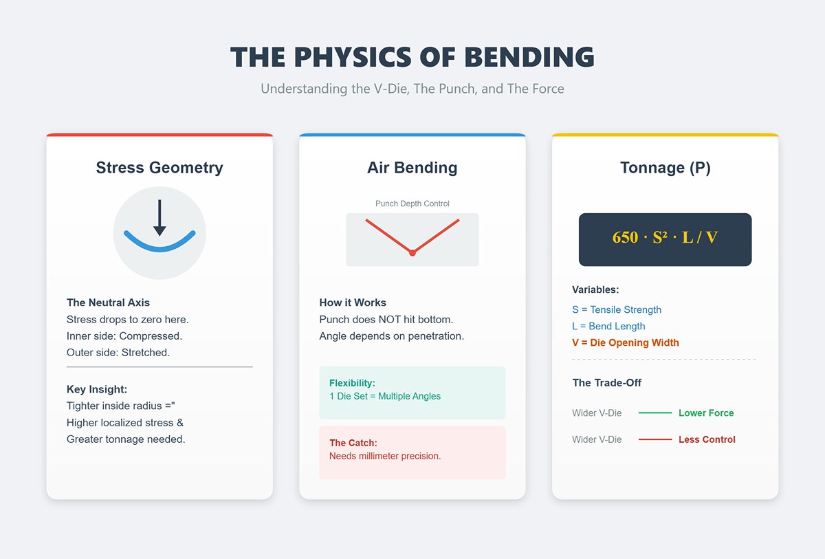
In air bending—the technique used most often—the punch stops before contacting the bottom of the die. The resulting bend angle isn’t determined by the die itself but by how deeply the punch penetrates. This approach offers flexibility: one punch‑and‑die set can produce multiple angles simply by adjusting depth. The catch is precision—changes in punch travel as small as a millimeter can noticeably alter the final angle.
The required bending force is no mystery. It follows structural relationships among material thickness (T), bend length (L), and tensile strength (S), which together determine the needed tonnage (F). For mild steel, a widely used approximation applies: P = 650 × S² × L / V, where V is the die opening width. Increasing V lowers the necessary tonnage but also sacrifices control—a trade‑off that newcomers often underestimate.
Bending combines two simultaneous behaviors: elastic and plastic deformation. Elastic deformation is temporary—the metal springs back once the pressure is released. Plastic deformation is permanent—it defines the final shape. In press brake operations, these two overlap, and that lingering elastic recovery explains why the finished angle doesn’t perfectly match the punch form after release.
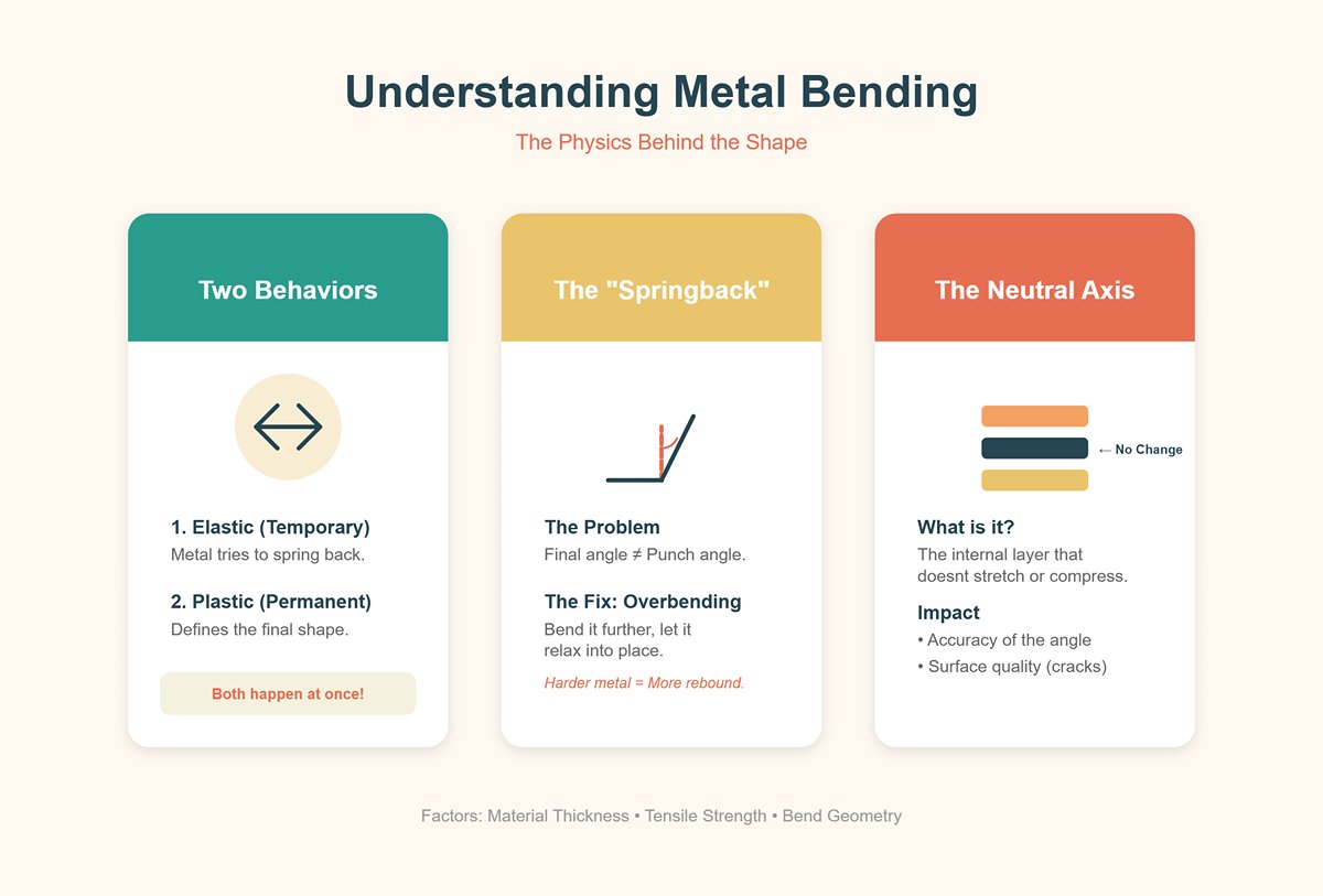
Springback can be predicted and managed. Materials with higher tensile strength rebound more strongly than softer metals. The standard solution is controlled overbending—pressing the piece slightly beyond the desired angle so it relaxes back into specification. Experienced operators fine‑tune this overbend allowance for each setup, considering thickness, material strength, and even batch‑to‑batch variations.
The neutral axis—a hidden layer within the bend that remains unchanged in length—is the pivotal element in bend mechanics. Its position shifts based on the material’s characteristics and the specifics of the bend geometry, dictating the balance between stretching and compression. These changes influence not only the accuracy of the final angle but also the visual quality of the surface, since excessive stress can cause visible blemishes or even cracks on the outer face.
Press brake bending focuses stress along a localized, linear point between the punch and die. Rolling, by contrast, shapes metal progressively as it passes through rotating dies, spreading deformation more evenly and producing smooth curves rather than sharp angles. Folding secures the workpiece along a set line and pivots the clamping beam to create the bend, a process that minimizes springback but limits both angle range and complexity.
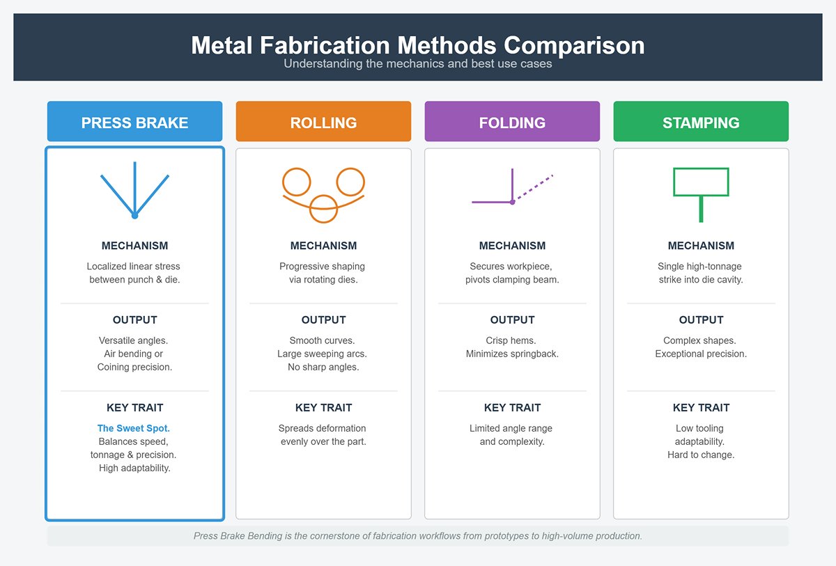
Stamping operates under a completely different stress profile—forcing the entire part shape into a die cavity in a single, high-tonnage strike. This achieves exceptional precision, but at the expense of tooling adaptability. In comparison, press brakes can tailor bend angles during air bending without swapping tools, or deliver tight tolerances through bottom bending or coining by adjusting force and penetration depth.
While rolling is ideal for large sweeping arcs and folding is best suited to crisp hems, press brake bending captures the sweet spot between accuracy and versatility. Its ability to balance speed, tonnage, and precision makes it a cornerstone of fabrication workflows, from one-off prototypes to high-volume production.
Three main bending techniques define the operational landscape:
Air bending demands the lowest tonnage and allows one set of tooling to achieve multiple angles. While it offers versatility through controlled penetration depth, angle consistency can vary due to springback fluctuations, keeping precision at a moderate level.
Bottom bending uses greater tonnage and more surface contact with the die, embedding the workpiece deeper. This approach trades some flexibility for improved accuracy and more consistent springback, making it well-suited for precision work with tight tolerances.
Coining applies the highest force, pressing the metal fully into the die to imprint the bend angle into the material. This virtually eliminates springback and delivers ultra-high precision, but limits flexibility and accelerates tool wear.
| Method | Tonnage Requirement | Accuracy Level | Tooling Wear | Operational Flexibility |
|---|---|---|---|---|
| Air Bending | Low | Moderate | Low | High |
| Bottom Bending | Medium | High | Moderate | Medium |
| Coining | High | Exceptional | High | Low |
Recognizing these factors shifts bending from a routine mechanical operation to a strategic decision-making process. The operator isn’t simply shaping metal—they’re balancing force, tooling geometry, and the inherent “memory” of the material to consistently hit that precise intersection between theoretical design and reliable, repeatable production.
Although air bending only gained traction in the 1970s, it has since become the go-to press brake method in many fabrication environments. In this process, the punch tip pushes the sheet metal into the V-die but stops short of full contact along the die walls. As a result, only the punch tip and die shoulders meet the material, and the bend angle is determined by penetration depth rather than die geometry. This limited contact slashes required tonnage—often to less than half that of bottom bending—and allows a single 85° V-die to produce a variety of angles by simply adjusting the depth of the punch stroke.
That versatility explains air bending’s dominance in cost efficiency and quick changeovers. With fewer dies to purchase, tooling expenses stay low, and operators can tweak bend angles without swapping components. However, precision suffers. Air bending leaves final angles heavily influenced by factors beyond full control: variations in sheet thickness, material strength, ductility, and how much the metal springs back after release. Even carefully chosen punch and die angles can yield inconsistent results when working with different alloys or batches from varying suppliers. For jobs requiring tight tolerances, this unpredictability transforms flexibility into a drawback.
Quick check: If each run demands repeated angle verification or continual adjustments for springback, the supposed savings from air bending may be costing you more in lost time and compromised accuracy.
In bottom bending, the sheet metal is pressed into the V-die until it fully contacts the die’s sidewalls. For accuracy, the punch and die angles must match the desired bend exactly, and the tooling must be suited to the specific material thickness. Once the sheet is fully seated, the press brake applies just enough force to push the metal slightly beyond its yield point, locking in the angle with minimal elastic rebound.
The advantage is precision. Because the bend angle is dictated by the fixed geometry of the punch and die instead of relying solely on penetration depth, springback is effectively controlled without constant retuning. This makes bottom bending ideal for production runs where consistent accuracy is key, such as in assemblies requiring exact fits. The downside is reduced adaptability: any change in angle or material thickness demands different tooling, which slows production and increases costs. For workshops that frequently produce custom pieces or incorporate design changes, this rigidity can outweigh its precision benefits.
In day-to-day use, bottom bending offers a middle ground—more accurate than air bending, consuming far less tonnage than coining, but limited by the need for tooling that matches your specific product range.
Coining takes bending a step further, applying controlled compression to the material. The punch drives the sheet 10–15% deeper into the die than the finished bend profile would require, imprinting the punch’s nose into the workpiece. This deep penetration demands three to five times the tonnage used in air bending—if a job needs 50 tons for air bending, expect 150–250 tons for coining the same material.
The payoff is absolute elimination of springback. After coining, the bend angle stays exact, regardless of metal hardness or thickness variations, because the material has been plastically reshaped to match the tooling’s geometry. This makes coining invaluable for high-precision, mission-critical parts—such as aerospace brackets, complex housings, or sealing components—where even the slightest angular discrepancy could undermine performance or fit.
The trade-off is the heightened wear and mechanical strain. Sustained high tonnage shortens the operational life of both the press brake and its tooling. Coining demands not just investment in capacity but also in rigorous maintenance, premium-grade tool steels, and long-term equipment care planning. It is the least tolerant of setup mistakes—any error under coining loads can cause immediate damage to both the machine and the workpiece.
An efficient way to boost bending accuracy without making a major tooling investment is to adapt an air bending configuration to mimic bottom bending when tighter tolerances are required. If a particular bend angle consistently suffers from springback, choose a punch and die set that matches the exact target angle and material thickness. Then, narrow the V-opening proportionally to increase precision. For instance, if you normally use a V-opening eight times the material thickness for air bending, reduce it to six times and deepen the stroke until the material seats firmly against both die shoulders.
Here’s what successful implementation looks like: your first test piece hits the target angle without any after-the-fact tweaking, and subsequent parts replicate that result consistently. Measurements reveal minimal springback, with fewer trial-and-error runs and greater uniformity across the batch. This straightforward adjustment lets you see whether bottom bending’s reliability outweighs the added tooling setup—before you commit to changing the entire process.
True precision bending starts well before metal meets the press—it begins with accurate calculations. A part that appears flawless on a CAD model can emerge from the brake a millimeter too short or too long if the flat pattern math or tooling selection is off. Predictable, repeatable results hinge on disciplined use of proven formulas and factors. These aren’t classroom theories—they’re the safeguards against bent edges splitting, tooling taking damage, and finished parts falling outside specification.
Every bend uses a precise amount of material as it curves around the die. That portion—known as the bend allowance—comes from straightforward geometry and the way metal flows during bending. Central to calculating it is the K-factor, which defines where the sheet’s neutral axis shifts as the bend is formed.
Standard guidelines often use a K-factor of about 0.33 for mild steel, which positions the neutral axis roughly one-third of the way through the thickness from the inside surface. Seasoned operators know that even slight deviations from this value can create measurable consequences. In practice, the K-factor may range anywhere from 0.30 to 0.45, influenced by factors like die width, inside bend radius, and whether the bend is formed in air or fully coined. Get the number wrong and dimensional errors quickly stack up—being off by just 0.3 mm per bend can lead to a full millimeter of misalignment in a three-flange bracket.
The quickest way to nail down the correct value is with a three-bend proof part. Cut a flat test piece, program it using your assumed K-factor, make three bends at fixed lengths, then measure the final outside dimensions. Reverse the calculation to determine the actual K-factor that produced those measurements. Once logged, that figure becomes a reliable input whenever you work with that specific material and tooling combination. Shops that invest a few minutes in this calibration consistently cut down on first-article tweaks and reduce scrap rates.
Even parts with identical thickness can end up with noticeably different results when bent using different dies. For example, 3 mm mild steel bent in a 24 mm V-die versus a 32 mm V-die will show variations because the larger opening shifts the neutral axis outward, making the finished part shorter. Air bending magnifies this effect, as the inside radius scales with die size—typically 0.16–0.20 × the V-opening for steel—altering the bend allowance as well. Coining, on the other hand, compresses the inner fibers through the full thickness until they yield, locking in an inside radius close to the material thickness and repeating with high accuracy. That level of consistency is why coining remains the go-to method when tolerances are extremely tight.
Without knowing the true K-factor for your tooling, you’re not really controlling your dimensions—you’re leaving your flat lengths to chance.
The size of the V‑die opening directly sets your bend radius, required tonnage, and edge finish—all in a single decision. Standard tonnage charts usually recommend V = 8 × T (where T is material thickness) for mild steel in air bending. This ratio delivers an internal radius of around 1.5–2 × T, provides good angle control, and keeps the load to a manageable level. However, following it without question is risky; sooner or later, that assumption can lead to damage.
Real-world conditions always require fine-tuning. For thin-gauge sheet or softer, nonferrous metals like aluminum and copper, you can often tighten the ratio to around 6 × T, since these materials offer less resistance and minimal springback. On the other hand, stainless steels and high-strength or abrasion-resistant plate call for a broader opening—typically 10–12 × T—to keep tonnage manageable and reduce the chance of cracking. The fundamental tradeoff never changes: smaller V‑dies sharpen control but cause a dramatic rise in tonnage. For instance, bending a 5 mm mild steel panel over 3 m may need roughly 108 tons with a 45 mm die (≈9 × T), yet the load surges past 180 tons when forced into a tight 25 mm die. Many seemingly inexplicable tooling failures trace back to overlooking that relationship.
There are times when the 8× rule simply doesn’t hold up. If flange lengths drop below the die opening, the workpiece can fall into the cavity, crushing corners or twisting the flange. In that case, a smaller V or a custom die is the only solution. Conversely, when a drawing specifies an inside radius equal to the material thickness, no 8× die can achieve it. Forcing the bend will only overload the tooling. The answer is to reduce the V‑opening while calculating the exact tonnage—or to switch to bottoming or coining, where geometry, not brute force, determines the final angle.
Mastering die selection isn’t about memorizing ratios; it’s about recognizing the moment when those ratios stop keeping your process safe.
Press brakes rarely fail from wear—they fail from assumptions. Operators who take a “one more bend” approach without checking their load calculations risk fractured dies or a bent bed. Tonnage for air bending can be found in manufacturer charts or estimated with this standard industry formula:
T (tons/m) = (1.42 × Tensile Strength × T²) / V
Here T is the material thickness (mm) and V the die opening (mm). Even a quick estimation helps—tonnage increases with the square of thickness, meaning that doubling the plate thickness multiplies the required force by four. That’s why an occasional 6 mm stainless job can produce loads that would easily crush tooling built for 3 mm mild steel.
Always check the machine’s rating per linear measure, not by total tonnage. A 135‑ton brake over 3 m yields only about 45 tons per meter before adjustments. Concentrating that same force into a short, narrow‑V setup causes local pressure spikes far beyond the rated capacity—the perfect recipe for cracks. Refer to pressure‑load distribution data from tooling suppliers, not just the press placard, whenever you set up a job.
Seasoned operators treat tonnage the same way a mechanic treats torque on a bolt—something to check carefully before applying more. The process is deliberate: choose the right die, calculate the precise force required, confirm it’s within the capacity of both the tooling and the press, and only then proceed with the first bend. That methodical approach safeguards not just your tooling assets, but also your production schedule.
Crunching the numbers might not feel exciting, but it’s the backbone of consistent results. In press brake work, geometry drives success far more than brute strength. When you understand your own K‑factor, the effective V‑die range, and your machine’s tonnage limits, mistakes become a conscious choice rather than an unwelcome surprise.
Springback is the inevitable recoil of material after bending, caused by the release of stored elastic energy once the punch is withdrawn. Operators can minimize its effects, but with standard air bending techniques, they can’t eliminate it entirely. The only true way to remove springback—coining—requires forces up to six times greater than air bending. For a mild steel sheet 2–3 mm thick, that’s in the neighborhood of 100 tons per meter, accelerating machine wear and increasing energy use.
One of the most straightforward ways to reduce springback is to narrow the V‑die opening relative to sheet thickness. Dropping from a die-to-thickness ratio of 12:1 to 8:1 can cut springback by as much as 40%, as the material is driven deeper into permanent deformation. Similarly, bottoming—pressing the punch firmly down until the workpiece conforms fully to the die—further curbs springback by leaving minimal elastic energy to push the material back.
Modern technology makes pinpoint compensation achievable. In‑process springback correction systems (IPSCS) measure angular variation during bending and fine‑tune the ram’s force in real time. Finite Element Analysis (FEA) of the bending process can anticipate springback within ±1°, enabling operators to choose tooling accordingly—such as selecting an 83° punch when anticipating about 7° of rebound—to ensure the finished angle lands exactly where it should.
Variations in material properties can magnify bending issues. Even sheets labeled under the same specification may differ in yield strength or thickness tolerance, leading to unpredictable springback from one batch to the next. Inputting precise, batch-specific data into the CNC controller, alongside running quick trial bends when introducing new stock, helps maintain consistent compensation settings. Much like a bow will release an arrow differently if its string tension changes, a press brake reacts to subtle shifts in steel or aluminum characteristics—and operators who fail to account for these changes often find themselves constantly chasing the correct angle.
Every rolled sheet carries an inherent grain direction, created by the alignment of metal crystals during the rolling process. This orientation influences both ductility and resistance to cracking during bending. Bending across the grain—perpendicular to the rolling direction—allows the material to stretch more uniformly, producing smoother bends and greater fracture resistance. In contrast, bending with the grain channels the elongation along crystal boundaries, making the material more brittle and increasing the likelihood of micro-cracks.
Minimum bend radius is closely linked to grain orientation. For instance, a 1.5 mm-thick sheet of 304 stainless steel might bend safely to a radius equal to its thickness when bent across the grain, but bending with the grain could require 1.5–2× thickness to prevent cracking. In high-strength aluminum alloys, grain-parallel bending can push the material to its critical strain limit even at larger radii, causing stress whitening or even splitting right at the bend apex.
In precision fabrication, considering grain direction starts with how you lay out the sheet. Align bend lines to maximize ductility and factor grain constraints into part nesting for laser cutting. If production realities mean bending with the grain, offset the risk by increasing the bend radius, adjusting punch geometry, or, for certain alloys, forming at higher temperatures. Overlooking grain orientation is like cutting wood without regard to its natural grain—control slips away, and the result becomes unpredictable.
When a bend angle varies along the length of a part, it usually points to uneven pressure distribution between the press brake’s ram and bed. The usual suspect is insufficient crowning—the compensation that offsets the machine’s natural deflection under load. Without this correction, the ram applies slightly greater force near its ends than at the center, causing the middle section of the bend to open up.
Mechanical issues can intensify the inconsistency. A misaligned ram—sometimes caused by improper transition between rapid descent and forming speed—can leave one side of the part with a different angle than the other. Worn or poorly aligned V-dies alter contact geometry, while hydraulic faults such as trapped air or weak return valves result in erratic ram motion. Likewise, guide rails that are too tight or unevenly adjusted prevent uniform downward travel, producing asymmetrical forming forces on the workpiece.
Avoiding crowning-related defects requires both technical precision and consistent maintenance. Manual crowning systems rely on tapered shims under the bed to raise its center slightly, whereas CNC-controlled crowning automatically adjusts lift based on tonnage, part length, and material properties. Whatever method is used, calibration remains essential. Weekly tool lubrication, periodic guide rail inspections, timely hydraulic oil replacement, and routine die alignment checks all preserve accuracy over the machine’s service life. Much like a carpenter depends on a perfectly level bench for square cuts, a press brake demands a geometrically true bed to deliver uniform bends from end to end.
Cracks appearing during bending usually signal that the radius-to-thickness ratio has been ignored. When the inside bend radius is too tight relative to material thickness, tensile strain on the outer surface surpasses the material’s elongation limit, leading to fractures.
Minimum allowable bend radii vary by material. Mild steel can often withstand an inside radius equal to its thickness, while high-carbon steels may require a radius two to three times thicker to prevent cracking. For aluminum 6061‑T6, bending with the grain may call for an inside radius up to four times the thickness—neglecting this guideline frequently causes white surface fractures or complete failure. Thinner gauge sheets tolerate smaller radii, but hardness, temper, and grain direction all influence the safe bending limit.
Press brake operators can reduce the risk of cracking by selecting punches with an appropriate nose radius, widening V-die openings to lower forming stress, or heat-treating certain metals through annealing before bending. As the bend radius-to-thickness ratio approaches the physical limit of the material, the danger escalates sharply—a slight reduction in radius can instantly double the chance of failure. Recognizing and respecting these limits is essential, particularly in aerospace, medical, or load-bearing structural work where product integrity is non-negotiable.
This same caution applies to surface finish quality. Even if a bend remains structurally sound, excessive strain may damage coatings or produce visible surface crazing. Achieving the right radius-to-thickness balance safeguards both performance and visual appeal.
Achieving a flawless bend goes far beyond simple calculations. Success depends on the interaction among material properties, tooling condition, and machine calibration. Mastery means understanding how springback will change the angle after release, how grain direction influences ductility, how precise crowning keeps angles consistent across the part, and how proper radius-to-thickness ratios prevent fractures. In press brake work, these aren’t peripheral details—they are the critical controls that determine precision.
Treat buying a press brake as launching a full-scale project, not just making a purchase. A simple price quote ignores the ecosystem you’ll need to operate it effectively. Budgets typically break down to around 55–65% for the brake itself, 15–25% for tooling, 5–8% for installation, 3–5% for training, and 7–10% for working capital reserves. That “$80,000” machine can easily grow into a $120,000 investment before producing a single finished part.
Tooling is essentially your second, hidden machine. Standard punches and dies might cover about 80% of your work, but real-world production inevitably brings a steady stream of exceptions—hemming dies, gooseneck punches, narrow V dies, and custom radii. Each unusual bracket or specialty job requires unique tooling, and over time these purchases can rival the original price of the brake itself.
Under-specifying capacity is a costly mistake. One shop saved $30,000 up front by choosing a lower-tonnage press brake, only to lose $50,000 annually in labor—extra setups, rework, and outsourcing thicker materials. The supposed “deal” turned into a negative payback in just one year. In reality, the cheaper brake proved to be an expensive liability.
Over time, the balance sheet shifts under the weight of energy and maintenance costs. All-electric brakes consume roughly 67% less power at peak load compared to hydraulic systems, reducing energy’s share of lifetime cost from 61% down to 28%. Maintenance requirements drop significantly as well—no pumps, valves, leaks, or oil degradation—saving an estimated $12,600 annually. For many operations, that means the all-electric’s roughly 25% higher purchase price pays for itself in just 2.3 years.
Beware the hidden costs of bargain brands. Low-cost imports might look identical on paper, but the lack of reliable local service can turn a routine fault into days of downtime. That delay derails production schedules, damages resale value, and can quickly wipe out any initial savings. In this business, rapid service response is a genuine asset—though it’s one your salesperson is unlikely to quantify.
Manual brakes win on upfront cost. They suit thin materials, short runs, and work paced to the operator. But bend angles rely entirely on human judgment—not measured precision—making quality hinge on your most skilled operator’s eyes and expertise. When that person is absent, scrap rates climb and timelines slip. The result: manual brakes don’t just shape metal, they reshape your workflow around a single individual.
Traditional hydraulic brakes earned their reputation by delivering versatile tonnage for heavier plate, at mid-range prices, supported by a mature service network. They’re tough, proven, and dependable. The hidden cost? Constant energy draw. Hydraulic pumps run continuously—even when idle—doubling the portion of lifecycle expense tied to energy compared to all-electric models. This ongoing drain creeps into utility bills quietly, rather than appearing as a line on a purchase order.
CNC-equipped brakes transform operations. With programmable control over backgauges, crowning, bend sequences, and springback adjustments, they deliver consistent results. Job-specific “recipes” reduce setup times and free you from dependence on any single operator’s skill. They can shrink learning curves from months to days—provided you invest in proper training. Without that, a CNC becomes just a complicated control panel, with operators falling back into manual trial-and-error.
Leasing should be seen as a strategic option, not merely a backup plan. For shops in fast-changing markets, it acts as insurance against your brake becoming outdated or underpowered within a few years. It helps maintain healthy cash flow, with payment schedules that can be tied to contract timelines. Frequent upgrades also mean you can avoid big fluctuations in energy consumption and maintenance expenses.
Purchasing gives you absolute control—no usage caps, no return conditions, no uncertainty at renewal. Ownership is the right move when production demands are steady, your maintenance team is capable, and the machine’s output will be fully utilized for years to come. For equipment embedded in a production line with job-specific tooling and programming, the operational disruption of swapping machines can easily outweigh the savings a lease might offer.
Often, the most effective approach blends both strategies: lease a high-spec CNC brake for new projects or contracts with unpredictable lifespans, and purchase a versatile hydraulic brake to handle long-term, core workload. This combination turns your bending capacity into a diversified portfolio—adaptable where uncertainty is high, and firmly anchored where operations are stable.
A press brake isn’t just metal and software—it’s an investment in a production ecosystem that can either magnify profits or steadily drain them. Stripped of marketing shine, the best choice lies where lifecycle cost, operator autonomy, and workload variability meet. A salesperson may be selling you a piece of equipment, but in truth, you’re setting the future speed and reliability of your entire bending operation. In the end, every part you produce will reflect this decision—so select the brake you can afford to operate sustainably, not just the one you can afford to purchase.


