

I watched a kid bolt a “universal” hemming wheel kit onto a 10-foot brake last winter. Fifty bucks. Slotted brackets, a bag of shims, bolts that looked like they came off gas-station sunglasses.
First test bend looked fine.
Second one? The hem wandered an eighth over eight feet. He blamed the coil. Then the brake. He never looked at the add-on.
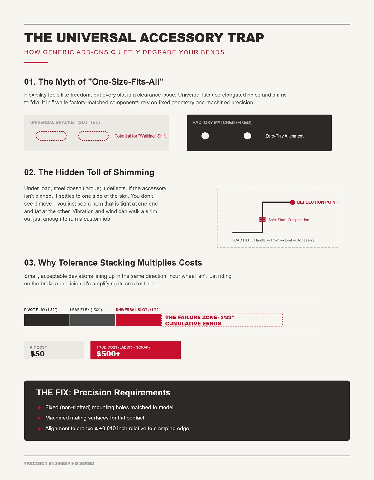
Lay a factory-matched wheel assembly on the bench next to a universal kit. The factory bracket has fixed holes, tight shoulders, machined faces that sit flat against the brake’s apron. The universal one has slots. Elongated holes. A stack of washers so you can “dial it in.”
That flexibility feels like freedom. One kit fits five brands. Costs half as much. You tell yourself you’re being smart.
But every slot is clearance. Every washer is a gap you’re filling by feel. I once ran a job where a “fits-anything” back gauge needed three shims per side to square up. We hit layout on day one. By day three, vibration walked one shim out just enough to throw our drip edge long on one end. Not dramatic. Just enough to fight it all week.
So what are those slots and shims actually doing to the geometry of your brake?
Picture the load path when you clamp 24-gauge steel: handle to pivot, pivot to leaf, leaf to nose, nose to your accessory. Now slip a slotted bracket and two washers into that chain.
Under load, steel doesn’t argue. It deflects. If the accessory isn’t pinned in a fixed position, it settles to one side of the slot. Next bend, maybe it settles the other way. You don’t see it move. You just see a hem that’s tight at one end and fat at the other.
I ruined a custom scupper pan years ago because I “made it work” with a shim stack under a universal stop. Dead-on in the shop. On the roof, in the wind, that stack compressed a hair different. The return leg opened up and we ate the metal.
You can tweak forever. Or you can ask why the system needs tweaking in the first place.
No brake is perfect. There’s always a little pivot play, a touch of leaf deflection, a whisper of frame twist. Within spec. Stable.
Now add a universal wheel kit with slotted mounts. Say the slot allows ±1/32 inch of side shift. Your brake already has 1/32 in the pivot and another 1/32 across ten feet of leaf flex under load. Best case, they cancel. Worst case, they stack.
That’s tolerance stacking — small, acceptable deviations lining up in the same direction. In automotive brake rotors, stacked tolerances make pads contact unevenly even when each part passes inspection. Same idea here. Your wheel isn’t just riding on the brake’s precision; it’s amplifying its smallest sins.
I saw a shop burn half a day chasing a “bad coil” that was really a universal roller walking in its slot. Fifty-dollar kit. Five-hundred-dollar delay once labor and scrap were counted.
Factory-matched accessories attack specific stack points: fixed hole patterns, machined shoulders, controlled flange orientation. They don’t ask you to average out error with washers and hope.
The Fix: Use accessories built for your exact brake model with fixed (non-slotted) mounting holes, machined mating surfaces, and alignment tolerance no greater than ±0.010 inch relative to the brake’s clamping edge — verified by the manufacturer, not “field adjustable.”
If a brake is a precision straightedge, universal add-ons are those cheap sunglasses at the gas station — they look clear until you try to read a level line through them.
So what, mechanically, is happening at the nose and pivot that makes a few thousandths turn into a crooked hem?
I put a dial indicator on the nose of a 10-foot brake once because a hem kept walking. Clamped tight, no material in it, just cycling the leaf. The needle twitched five thousandths at the pivot.
Five thousandths doesn’t sound like a crime. You can’t see it. You can barely feel it.
But the nose on that brake sat 2-1/2 inches from the pivot centerline. The hem we were running stood 1 inch tall. That tiny pivot shift changes the arc the nose travels through. Over ten feet, that arc isn’t theoretical — it’s steel. What starts as 0.005″ of radial play at the hinge becomes a lateral shift at the contact line because the leaf is rotating, not sliding. The farther you get from the pivot, the more that movement stretches out.
That’s geometry, not opinion.
And when you bolt a universal accessory onto the nose, you’re not just adding a part. You’re adding another joint in the kinematic chain — another place where rotation, clearance, and flex can compound. The brake was built as a system with one controlled pivot axis. Now you’ve got a pivot feeding a bracket feeding a roller feeding your material. Each interface can move. Each one has clearance. But every slot is clearance.
So what exactly changes when an accessory is bolted on instead of engineered in?
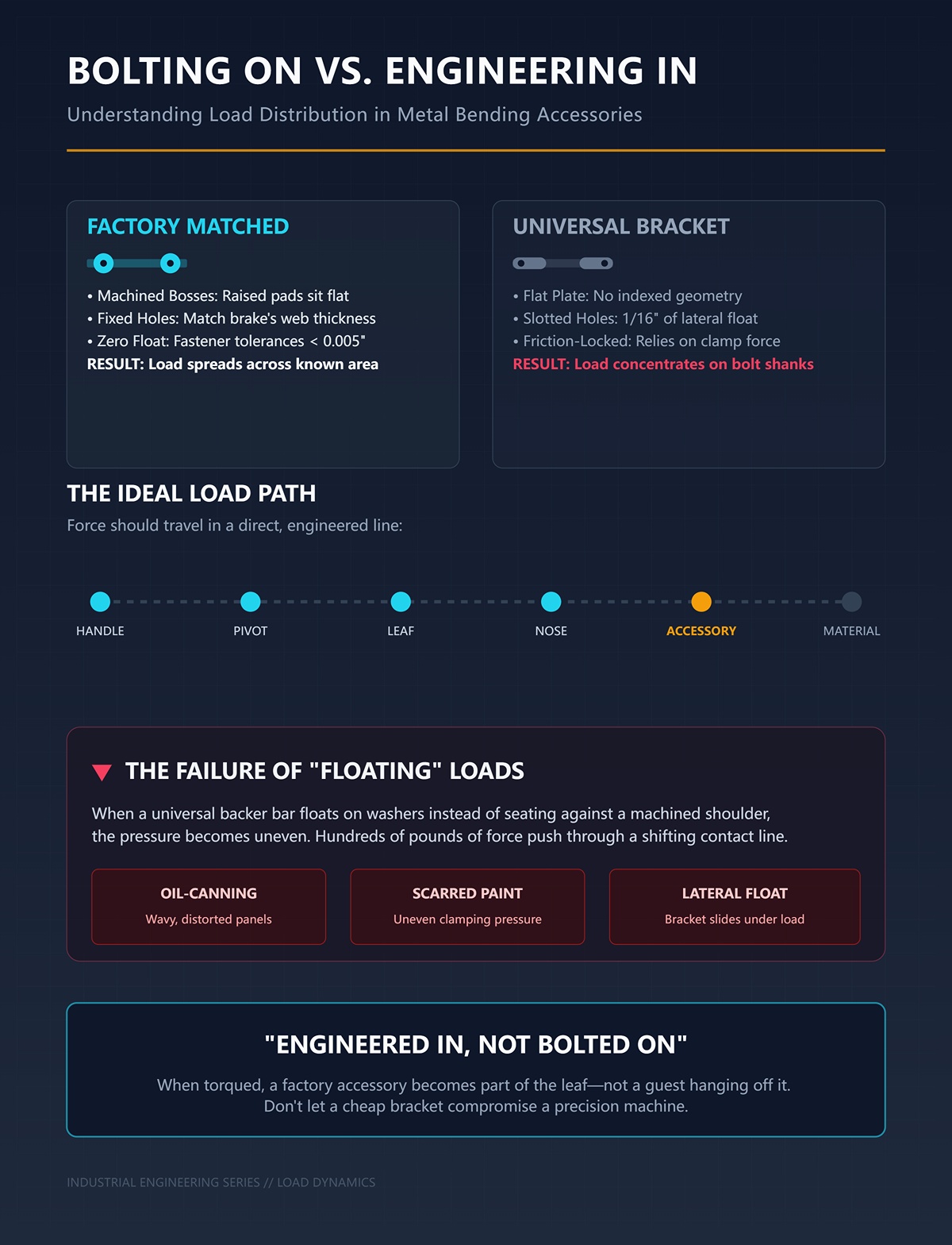
Set a factory hemming wheel bracket next to a universal one and flip them over. The factory piece usually has machined bosses — raised pads that sit flat against the leaf — and fixed holes that match the brake’s web thickness and bolt spacing. When you torque it down, the load spreads across a known surface area.
A universal bracket? Flat plate. Slotted holes. Maybe a couple washers to “take up space.”
When you clamp 24-gauge and swing the leaf, you’re pushing hundreds of pounds through that contact line. The load path should go: handle → pivot → leaf → nose → accessory → material. Clean. Direct. Engineered.
Bolt-on universals change that path. The clamping force now concentrates around bolt shanks because the bracket isn’t indexed to the leaf geometry. If the slot is 3/8″ wide for a 5/16″ bolt, you’ve got 1/16″ of lateral float before friction locks it in. Under load, the bracket slides to one side of the slot and bears there. Release. Next bend, it may settle differently depending on where the metal grabs first.
I watched a crew fight oil-canning on prefinished panels for two days because a universal backer bar wasn’t seated against a machined shoulder — it was floating on washers. By the time we pulled it off, the paint was scarred from uneven pressure. That job didn’t fail because the brake was cheap. It failed because the load wasn’t distributed where the engineer designed it to be.
Factory-matched accessories are engineered in. The bolt holes are sized within a few thousandths over the fastener diameter. The mating face is machined flat. When torqued, the accessory becomes part of the leaf — not a guest hanging off it.
If the load path changes, what happens to the lever that’s actually doing the bending?
| Section | Content |
|---|---|
| Title | Mounting Points vs. Load Distribution: Bolting On vs. Engineering In |
| Factory Bracket Design | Factory hemming wheel brackets typically feature machined bosses—raised pads that sit flush against the leaf—and fixed holes aligned precisely with the brake’s web thickness and bolt spacing. When torqued, the load distributes across a defined, engineered surface area. |
| Universal Bracket Design | Universal brackets are usually flat plates with slotted holes, often requiring washers to fill gaps. They lack indexing to the specific leaf geometry. |
| Intended Load Path | When bending 24-gauge material, hundreds of pounds of force travel through a defined path: handle → pivot → leaf → nose → accessory → material. This path is designed to be clean, direct, and engineered. |
| Effect of Bolt-On Universals | Slotted holes (e.g., 3/8″ slot for a 5/16″ bolt) allow lateral float before friction locks the bracket in place. Under load, the bracket shifts within the slot and bears against one side. On release, it may settle differently during the next bend, depending on material contact. |
| Load Concentration Issue | Instead of distributing force across a machined surface, bolt-on universals concentrate clamping force around the bolt shanks, altering the intended load path. |
| Real-World Consequence | A universal backer bar floating on washers instead of seating against a machined shoulder caused uneven pressure, oil-canning, and paint damage on prefinished panels. The failure stemmed from improper load distribution—not equipment cost. |
| Engineered-In Accessories | Factory-matched accessories have bolt holes sized within thousandths of the fastener diameter and machined mating faces. When torqued, they integrate with the leaf as a structural component rather than acting as an attachment. |
| Key Consideration | If the load path changes, what happens to the lever that’s actually doing the bending? |
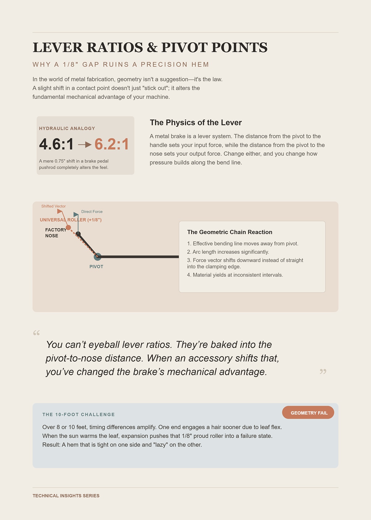
You ever look at pedal ratios in hydraulic brakes? Move a pushrod hole three-quarters of an inch and you swing the ratio from 4.6:1 to 6.2:1. Same leg, same car. Completely different feel. In automotive brake rotors, stacked tolerances make pads contact unevenly even when each part passes inspection — and that’s with engineered geometry.
A metal brake is a lever system too. The distance from the pivot to the handle sets your input force. The distance from the pivot to the nose sets your output force. Change either, and you change how pressure builds along the bend line.
Now picture a universal roller assembly that spaces the contact point 1/8″ farther forward than the factory nose profile. That doesn’t just “stick out” a bit. It moves the effective bending line away from the pivot. The arc length increases. The force vector shifts slightly downward instead of straight into the clamping edge.
On a shallow bend, you won’t notice. On a tight hem, that extra 1/8″ changes when the material yields. One end of the brake might engage a hair sooner if there’s existing leaf flex. The other end follows a split second later. Over eight or ten feet, that timing difference shows up as a hem that’s tight on one side and lazy on the other.
I once signed off on a fascia run where the first three sticks were dead straight. Then the sun warmed the leaf, expanded it just enough, and the universal roller — already sitting 1/8″ proud — started over-closing the leading end. We ate six panels before we traced it back to geometry, not technique.
You can’t eyeball lever ratios. They’re baked into the pivot-to-nose distance. When an accessory shifts that distance, even slightly, you’ve changed the brake’s mechanical advantage.
And that’s before we talk about what happens when the materials touching each other don’t agree.
Take a hardened steel roller and run it along an anodized aluminum rail under load. The steel doesn’t care. The aluminum does.
Most factory systems match surface hardness and finish. If the leaf cap is aluminum, the mating wheel might be nylon, UHMW, or coated steel — something that won’t gall or brinell (that’s permanent indentation from contact stress). The contact patch is calculated so pressure stays below the yield strength of the softer material.
Universal kits don’t know what they’re mating to. So they default to hardened steel. It’s durable. It’s cheap to machine in bulk. Looks tough.
Under repeated cycles, that hard roller creates microscopic grooves in a softer rail. Those grooves become tracks. Now the roller doesn’t just ride — it indexes. It prefers the low spots. That means your accessory is self-aligning to wear patterns, not to the original brake geometry.
I saw an aluminum leaf that looked fine to the eye but had developed faint witness lines from a universal steel wheel. Every time we ran a hem, the wheel snapped into those lines and dragged slightly toward the center. The result was a consistent 1/16″ creep over ten feet. Subtle. Expensive.
Factory-matched systems account for hardness pairing and surface finish. They control contact stress so wear is predictable and even. Universals gamble on “strong enough.”
Strong enough for what?
Let’s stack it clean.
Say your brake pivot has 0.005″ vertical play. Within spec. The leaf, under load across ten feet, deflects another 0.010″ at mid-span. Also normal. Now add a universal bracket that flexes 0.005″ because it’s flat plate instead of ribbed or gusseted.
Individually, none of those numbers scare you.
Together, they change the nose position relative to the clamping edge by as much as 0.020″ at certain points in the stroke. On a 1″ hem, 0.020″ is 2% of the leg height. That’s visible. More important, it’s not uniform — it varies across the length because deflection isn’t perfectly linear.
That variation turns into angle drift. One end of the brake hits 178 degrees while the other sits at 176. You tweak pressure to compensate. Now the center overbends. You chase it all day.
I ruined a custom coping detail on a copper cornice because I trusted a universal stiffener bar that flexed just enough under the last 10 degrees of closure. The sample piece was perfect. Production pieces weren’t. Copper doesn’t forgive overworking.
Five thousandths at a pivot doesn’t stay five thousandths at the hem. It multiplies down the length of the panel through lever arms, deflection curves, and contact geometry. Add one accessory with its own flex and clearance, and you’ve built a distortion amplifier.
Factory-matched systems don’t eliminate physics. They control it. Fixed hole locations within ±0.010″. Mating surfaces machined flat within 0.003″ across their contact face. Brackets gusseted to limit deflection under rated load. Contact materials specified to avoid galling and track wear.
The Fix: Use factory-matched accessories with fixed (non-slotted) mounting holes sized no more than +0.005″ over bolt diameter, machined mating faces flat within 0.003″, pivot-to-contact geometry identical to the OEM nose profile, and structural reinforcement rated to keep accessory deflection under 0.005″ at full bending load.
Geometry is static. Steel under load isn’t.
So what happens when vibration, temperature swings, and roof-level abuse start shaking that carefully—or carelessly—assembled stack?
Last August we were bending 24-gauge coping on a rooftop, 92 degrees in the shade. The brake had a universal wheel kit bolted on so we could “roll it easy.” By noon the panels started coming off with a 1/8″ crown over ten feet. Same settings. Same operator. The only thing that changed was heat and the way the stand was sitting on that tar-and-gravel sponge of a roof.
You’re asking what vibration, temperature swings, and jobsite abuse do to those tiny geometric errors we already stacked up. Here’s the answer: they don’t create new problems. They wake the old ones up. Steel expands about 0.0000065 inches per inch per degree Fahrenheit. Over a ten-foot rail, a 40-degree swing is roughly 0.030″. If your factory stand constrains that expansion evenly, the brake grows as a unit. If a universal stand grabs it at four sloppy tabs with slotted holes, one corner binds first. The frame twists microscopically. Now your carefully aligned pivot-to-nose geometry is bending around a shape that’s changing with the weather.
You don’t see 0.030″. You see a hem that closes tight on the left and shy on the right.
And you blame the sheet.
Mobility is the trap here. Portability isn’t neutral. The minute you lift a brake off a rigid base and set it on wheels and legs, you’ve introduced another structure into the load path. If that structure flexes before your clamping bar does, your brake is bending around the floor instead of the metal. The shop floor is flat and continuous. A rooftop is neither. Add a generic stand that was drilled to “fit most models,” and you’ve just turned a precision instrument into something wearing gas-station sunglasses — looks fine until you rely on it.
So the real equation isn’t “Can I move it?” It’s “What deflects first under load?”
Picture a 10′ brake cycling through a tight hem. The leaf snaps over center, and that snap sends a shock through the frame. On a factory base with cross-bracing tied into the brake’s mounting pattern, that energy disperses through a triangulated structure. On a generic stand made from flat plate and bolt-on legs, that same shock hits slotted joints and single-shear bolts.
But every slot is clearance.
Clearance means motion before resistance. Under vibration, those micro-movements fret the bolt holes. The holes oval out. Now the brake isn’t just sitting on a stand — it’s perched on four tiny hinges you didn’t ask for.
I watched a crew chase angle drift for two days on stainless counterflashing. Turns out the universal stand’s rear crossbar had developed visible play at the bolts. Every time the leaf closed hard, the stand flexed backward maybe 1/32″. Doesn’t sound like much. But at the nose, through the lever arm, that translated to inconsistent closure pressure across the length. We re-bent twelve pieces before we tore the stand off and set the brake on timber cribbing. Problem vanished.
The paradox is this: guys think a little flex “absorbs vibration.” It doesn’t. It delays load transfer, then releases it unevenly. That delay changes timing across the brake length. One end loads first, the other catches up. Over and over. That’s how uniform geometry becomes a wave.
The Fix: Stand structure must exceed the brake’s frame stiffness — boxed or gusseted members, no slotted mounting holes, bolt holes no more than +0.005″ over bolt diameter, and cross-bracing that ties into the manufacturer’s specified mounting points so stand deflection stays below 0.005″ under full bending load.
If vibration is the pulse, weight transfer is the slow twist that follows.
Set a brake on fixed legs and the load goes straight down. Bolt on a universal wheel kit and you’ve changed where the weight sits. Most kits hang casters off one side with a pivoting axle so you can tip and roll. Great for moving. Terrible for symmetry.
When you lower it back down, all four feet rarely share the load evenly. One caster bracket is shimmed with a washer. One leg sits in a roof seam. The brake frame, designed to rest on a plane, is now supported at four points that aren’t co-planar. That’s a torsion setup.
I measured it once with a machinist level across the clamping bar. On a shop floor, bubble dead center. On a roof with a universal wheel kit installed, bubble drifted to one side as soon as we tightened the mounting bolts. We hadn’t even bent anything yet. The act of cinching down the kit twisted the frame a few thousandths.
In automotive brake rotors, stacked tolerances make pads contact unevenly even when each part passes inspection. Same story here. The brake frame is within spec. The wheel kit is within its loose spec. The roof is “flat enough.” Stack them and you get diagonal preload through the rails. Now when you clamp a panel, one end bites harder because the frame is already carrying torsion.
I lost a Friday on a long fascia run because the right end consistently overbent by two degrees. We kept tweaking pressure. The real culprit was a universal wheel bracket that sat 1/16″ proud, lifting that corner just enough to bias the entire frame. Fifty bucks saved on wheels cost us a full day of labor.
Mobility shifts the center of gravity and the support geometry. If that shift isn’t engineered into the brake’s frame, you’re bending on a twist.
So how do you move a brake and keep it straight?
A factory-matched mobility base doesn’t just bolt on casters. It integrates leveling screws at each support point, tied directly under the structural rails. You roll into position, drop the wheels, and dial each corner down until the frame is planar. Not “looks level.” Planar — meaning no twist across the mounting rails.
That’s the difference.
Leveling screws give you controlled preload. You can compensate for a soft roof deck, temperature-induced expansion, or a crowned slab. And because the mounting pattern matches the brake’s designed load path, tightening one corner doesn’t rack the frame.
I once replaced a universal stand under a 12′ brake with the OEM base that had integrated leveling feet and fixed mounting holes. Same roof. Same crew. Same material. The only change was support geometry. The random 1–2 degree angle drift across the length disappeared. We stopped chasing settings and started trusting the machine again.
Factory systems treat mobility as part of the structural design, not an afterthought. They assume the brake will see vibration, heat swings, and abuse — and they give you adjustment points to neutralize those forces instead of amplifying them.
The Fix: Use manufacturer-matched mobility bases with integrated leveling screws at each structural support, fixed (non-slotted) mounting holes aligned to OEM patterns, and caster assemblies that fully disengage from load during bending so the brake rests on adjustable, rigid feet — not wheels.
Portability isn’t the enemy. Uncontrolled support geometry is.
And when that instability starts interacting with cutting attachments bolted to the same flexing frame, what do you think happens to workflow speed?
Bolt a universal cutter onto a brake that’s already flexing on a generic stand and you’ve just tied a measuring instrument to a moving target. The cutter rides the hinge rail; the hinge rail is twisting; the stand is giving back 1/32″ every time you close hard. You pull the head down the length thinking you’re saving steps. What you’re really doing is tracing a curve that wasn’t there on the shop floor.
I watched a crew skin a long rake edge with a clamp-on slitter mounted to a brake sitting on a wheeled aftermarket base. Every cut started square at the operator’s end and walked off by the time it reached the far upright. Not dramatic. Maybe a fat 1/16″ over ten feet. Enough that hems wouldn’t nest tight at install. They blamed coil. They blamed blade. It was the frame racking under them.
Speed only counts if the reference line stays put.
Set a dial indicator on the hinge rail and close the leaf under load. On a rigid, leveled base, you’ll see a few thousandths of vertical movement—elastic, predictable, returning to zero. Now put that same brake on a slotted universal stand and repeat. You’ll see the rail drift laterally as the bolts shift in clearance and the rear crossbar breathes. But every slot is clearance.
An integrated tracking cutter—like a factory system with a four-wheel carriage riding machined faces—assumes that rail is a straight datum. Its wheels are spaced to preload against those faces so it can’t yaw or climb. That preload only works if the rail geometry stays stable. When the rail twists, the carriage doesn’t “float.” It binds at one wheel, unloads at another, and the blade enters the metal at a slight angle. That’s where the wander starts.
Aftermarket bidirectional cutters can be slick in workflow. I’ve run one that stays parked with a 1″ offset and auto-locks both directions so you don’t remove it between bends. That’s smart design. But it’s built to fit multiple generations and models, which means its clamp and wheel geometry must tolerate variation. Tolerance means freedom. Freedom means motion under load. In automotive brake rotors, stacked tolerances make pads contact unevenly even when each part passes inspection. Same physics here: brake rail within spec, cutter carriage within spec, stand within spec—stack them and the blade no longer tracks the true axis.
You don’t feel that in your hand. You see it when panels won’t line up.
The Fix: Use a cutter whose wheel spacing, bearing preload, and cam-lock interface are engineered to your exact brake model and rail profile, with fixed mounting points (no slotted clamps) and manufacturer-specified torque so carriage yaw under full leaf load stays under 0.003″ across the cut length.
If the carriage can’t trust the rail, what makes you think the shear can trust the bed?
Take a 10′ sheet of 24-gauge painted steel and run it through a sharp shear that’s out of parallel by a few thousandths end to end. The blade will still slice. It just won’t slice evenly. One end gets proper clearance—clean fracture zone, tight edge. The other end gets excess clearance—rollover and burr.
I ruined a stack of counterflashing once chasing a “dull blade” that wasn’t dull. The universal shear head was clamped to the brake bed, and the bed was carrying torsion from a wheel kit that never sat flat. When we tightened the shear clamps, we locked that twist into the shear frame. The blade gap measured within spec at the operator’s end and opened up downfield. We kept swapping blades like gas-station sunglasses—looks fine until you rely on them.
Blade sharpness is maintenance. Alignment is geometry. Geometry wins.
Factory-matched shears index off machined surfaces that mirror the brake’s load path. The mounting bosses are located where the frame is stiffest, not just where there’s room for a bolt. Older brake generations can trip you up here; even OEM cutters often require cam-lock compatibility. That’s not marketing fluff. It’s an admission that alignment depends on exact interface geometry. Age mismatch is just another form of universality.
The Fix: Mount only shears designed for your brake generation, using OEM indexing surfaces and specified shim packs (if any), and verify parallelism with feeler gauges across the full blade length—target uniform clearance per manufacturer spec, typically in the 0.002″–0.004″ range for 24-gauge steel.
Clean cut, straight edge. Now you want to move faster with a slitter.
Run a universal slitter head down coil stock and you can process panels quick. I get the appeal. On a high-volume week, minutes matter. But look at the edge under light. A consistent, factory-aligned slitter leaves a narrow burnish and minimal burr because the upper and lower knives stay coaxial as the carriage travels. When the brake rail is twisting or the slitter mount allows a hair of tilt, the knives lose perfect overlap. You get a feathered burr that’s almost invisible until you hem it.
That burr becomes trapped in the fold. It props the hem open just enough that water can wick, or it prints through light-gauge trim in sun. I had a fascia run where every third piece showed a faint line at the hem after install. The culprit wasn’t the painter. It was a universal slitter riding a rail that dipped under load, leaving a micro-burr we didn’t catch in the shop.
You saved a pass with a file. You bought a callback.
Workflow speed isn’t about how fast the head moves. It’s about how few times you have to touch the same piece. When cutters, shears, and slitters share the same engineered alignment as the brake—same load path, same datums—speed and precision reinforce each other. When they’re just “compatible,” you’re stacking tolerances and hoping they cancel out.
Hope isn’t a production strategy.
You want to know how to set up the whole system—stand, brake, attachments—so tolerance stacking dies in the shop instead of on the wall.
Start by sorting parts into two piles: anything that carries load or sets alignment, and anything that just rides along.
If it carries load or establishes a datum (a reference surface the rest of the system trusts), it must match the brake’s geometry. If it doesn’t, you’ve just reintroduced the same slop we’ve been hunting—only now you paid for it twice.
That’s the reality check.
Brand loyalty isn’t religion. It’s geometry control. But where does that line actually sit?
Factory accessories are built around a specific rail profile, hinge spacing, and cam-lock depth. That means the contact surfaces are machined to sit flush where the brake frame is stiffest, not just wherever a bolt can grab.
Aftermarket “fits most” parts have to forgive variation. Forgiveness means clearance. Clearance means motion under load.
I watched a crew bolt a universal back gauge onto a brake that was dead straight on its own. The gauge had slotted mounting tabs—nice and flexible, like gas-station sunglasses. Looked fine on install. Under a full 10-foot bend, the brake leaf flexed, the slots let the gauge shift a hair, and every return leg came out long on one end. Not by much. Enough to fight every piece into place.
“Close enough” is a moving target once the leaf is under tension.
Now, here’s the part that messes with your head: even factory parts aren’t universally compatible within the same brand. Some cutters only fit cam-lock models, not entry-level versions. That’s not corporate greed. That’s geometry. Different hinge castings, different rail heights, different load paths.
So the rule isn’t “always buy OEM.” The rule is “match the exact interface geometry.”
If the accessory references a machined surface and locks without slots, you’re safe. If it needs shims, persuasion, or “a little wiggle room,” you’re stacking tolerances again.
Run two different brakes long enough and you’ll feel the difference in how they close. One might cam over tight and linear. Another might have a softer hinge feel. That “feel” isn’t marketing fluff—it’s hinge geometry and pivot location changing the load path through the frame.
Accessories are built around that feel.
Mounting standards—rail shapes, cam-lock depths, carriage wheel spacing—aren’t arbitrary. They’re the brake’s skeleton. A third-party accessory that’s truly engineered for a specific model can work beautifully because it respects that skeleton. Some aftermarket companies machine their mounts to Tapco’s rail profile within tight tolerance and avoid slotted clamps altogether.
That’s not universal. That’s model-specific without the brand badge.
But a generic cross-brand mount has to hedge its bets. It can’t assume your rail height is exact. It can’t assume hinge alignment is perfect. So it builds in adjustment. Adjustment becomes play. Play becomes yaw when you load the leaf.
And yaw shows up at the blade.
I once tried adapting a carriage from one brand onto another because the bolt pattern was “almost” right. We made it fit. Under light cuts, it behaved. Under heavy gauge, the carriage cocked just enough that the cut walked off line over ten feet. Not dramatic. Just enough to scrap a day’s worth of rake trim.
Lock-in isn’t about loyalty. It’s about eliminating variables at the interface that matter most.
So where can you actually relax without sabotaging yourself?
Not everything on a brake is sacred.
Blades? If they meet the steel spec and hardness rating, fine. Clamping pads, handles, measuring tapes, even certain material stops that don’t carry bending load—these can be brand-agnostic as long as they don’t establish alignment.
If the part doesn’t define a reference plane or resist bending force, it doesn’t control geometry.
Think of the brake like a tuned level. The frame, hinge, rail, cutter carriage—those are the vial and the machined edges. Swap those carelessly and the bubble lies. But a different grip tape on the handle? Doesn’t change level.
I’ve run aftermarket clamping pads that actually improved grip without affecting alignment because they sat on existing machined surfaces and introduced zero play. No slots. No shims. Just material change, not geometry change.
That’s the distinction: material versus geometry.
If the accessory alters stiffness, pivot location, rail engagement, or mounting datum, commit to model-specific. If it just wears out or helps you hold material, universal is fine.
And then there’s the part nobody thinks about until something cracks.
When you bolt a load-bearing accessory onto a brake, you’re not just affecting alignment. You’re changing stress distribution.
Manufacturers design hinge castings and rails around expected forces. Add a stiffener, a shear, or a cutter that transfers load differently, and you may concentrate stress where the frame wasn’t meant to see it.
I saw a hinge ear fracture on a brake that had a heavy third-party shear mounted slightly off the recommended index surface. It cut fine—for a year. Then the casting gave up. Warranty claim? Denied. The mounting pattern told the story.
That’s the hidden cost of “saving” money up front.
But don’t swing to paranoia. Some branded add-ons exist precisely to protect known weak points—like cutters that distribute force across the cam-lock instead of the hinge edge. Those work because they’re engineered for that exact geometry.
So here’s the practical filter you run in your shop:
Does this accessory reference factory-machined surfaces without slots? Does it mount where the frame is designed to carry load? Does it avoid altering pivot relationships or rail alignment? Does it match my exact model generation—not just the brand?
If yes, you’re controlling geometry. If no, you’re gambling on stacked tolerances canceling out.
And hope, like we said, isn’t a production strategy.
So how do you turn that filter into a repeatable setup process for the whole brake—stand to blade—so you can prove alignment instead of guessing at it?
You don’t turn the geometry filter into a process by buying better parts. You turn it into a process by deciding what your brake is supposed to do all week, then locking every load‑bearing interface to that reality.
A brake is a precision instrument. Treat it like a tuned straightedge, not a Christmas tree for bolt‑ons. Universal accessories are gas-station sunglasses—look fine in the store, distort everything once you rely on them. The non‑obvious move is this: you stop asking “Will this fit?” and start asking “Does this protect my reference planes from stand to blade under my actual job mix?”
So what are you actually bending most days?
Roofing crews live in long runs and repeat angles. Siding guys chase short returns and hems. Custom fab shops bounce between materials that don’t behave the same under load.
Here’s where most contractors lie to themselves. They say, “We do a bit of everything.” That’s how you justify universal accessories. But every slot is clearance. Clearance is play. Play is angle drift once the leaf sees tension.
Material makes this sharper. Aluminum bends easy. Stainless fights back. If your week swings between them, a generic stop or add‑on calibrated around “typical steel” will pass inspection on one and miss by half a degree on the other. In automotive brake rotors, stacked tolerances make pads contact unevenly even when each part passes inspection. Same disease here. Each part is “within spec.” The system isn’t.
I ruined a batch of stainless counterflashing early on because we set the brake for aluminum in the morning and trusted the same universal back gauge after lunch. Looked close. Wasn’t. We chased the angle all afternoon and blamed the metal.
The Fix: Define your dominant material and thickness range in writing. Set your brake cam pressure, clamping force, and back gauge reference off that material first. Any accessory that establishes angle or depth must be model‑specific and calibrated under that load—not under “average steel.”
Once you know what you bend most, the next question gets uncomfortable.
You say you need speed. Usually you need repeatability.
Mobility matters if you’re hauling to jobs daily. But wheel kits and folding stands change support geometry. If they don’t lock the frame flat within a tight plane, you’re bending around the floor instead of the metal. Speed accessories—quick stops, snap‑in gauges—promise minutes saved, but if they mount with slotted brackets, they quietly move your datum.
I once bolted on a “high-speed” universal stop system because we were behind schedule. It shaved seconds per bend. It also had enough lateral play that over ten feet the hem walked just shy of a sixteenth. Not dramatic. Just enough to scrap a visible fascia run.
Bottlenecks hide in rework, not cycle time.
So name it clean. If you lose time re‑measuring, your bottleneck is repeatability. If setup takes forever because you’re shimming stands, it’s mobility. If your crew waits on you to dial angles, it’s calibration discipline—not hardware.
The Fix: For mobility, use a factory base that indexes to the brake’s frame rails with no slots and locks level at all four corners. For repeatability, use a model‑specific back gauge that references machined surfaces and locks without shim packs. For speed, only add features that do not introduce adjustable play at a load path.
Before you bolt anything on, though, you need to know what shape your brake is already in.
Accessories don’t fix worn pivots. They hide them.
Start at the stand. Level it. Then check rail parallelism end to end. Check hinge play under load, not just at rest. Close the leaf on a known straight test strip and measure angle consistency across the full width. You’re proving your reference planes.
If you add a stiffener or shear to a frame that’s already racked, you’re freezing misalignment into the system. That’s how hinge ears crack and rails dish over time. I saw a crew bolt a heavy third‑party shear onto an older brake to “tighten it up.” It cut straighter—for a while. Then the frame stress showed up as inconsistent bends we couldn’t chase out.
New hardware can feel like progress. It can also be camouflage.
The Fix: Before any upgrade, document three baselines: rail straightness, hinge play under clamped load, and full‑width angle consistency within your target tolerance. If the brake cannot hold consistent angle across its width with no accessories attached, repair or rebuild before adding anything that transfers load.
Now you’ve got a brake that’s true. The last question is why staying disciplined about that system pays you back every single job.
When every load‑bearing accessory is matched to the brake’s geometry, bends land where you expect them to. Not because the brand is premium. Because the interfaces are controlled.
That’s the shift I want you to carry forward: stop thinking in parts, start thinking in load paths. From stand to frame, frame to hinge, hinge to leaf, leaf to blade—each connection either preserves your reference plane or distorts it. Universal add‑ons distort by design because they must “fit” too many geometries. Factory‑matched systems eliminate the guesswork at the exact surfaces that matter.
Fifty bucks saved on a generic mount disappears the first time you scrap a visible run. But the real return isn’t the money. It’s confidence. You close the leaf and already know where the angle will land.
When you treat the brake as a system instead of a pile of features, you’re not hoping tolerances cancel out. You’re preventing them from stacking in the first place.
And once you start seeing every accessory as either protecting or polluting a reference plane, you’ll never shop the same way again.


