

A lid rocks on one corner.
Three 90-degree bends. Each off by half a degree. The print allowed ±1 degree, and the local shop swore they were “well within spec.” On paper, they were right. On the assembly table, the box wobbled like a bad restaurant table.
That’s the gap you’re standing in — the space between “within tolerance” and “won’t bolt together.” So where does it actually start?
You approved the quote because bending looked simple. Ninety degrees is ninety degrees. The vendor said they’ve been running that brake for 20 years. The price was half of the CNC house across town.
Then your assembler grabs a mallet.
In the shop we call that a “persuader” — a hammer used to force parts into alignment. Plain English: rework you never budgeted for. The bend was technically acceptable. The assembly is not. That disconnect is where the false economy hides.
So is the problem really the operator?
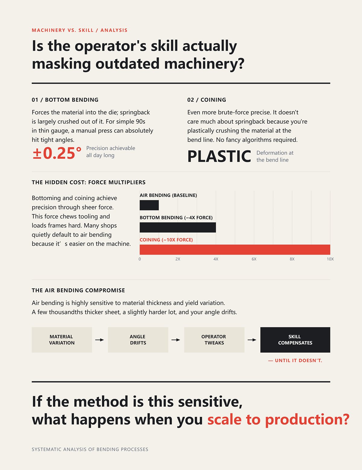
I’ve watched old-timers bottom-bend thin sheet to ±0.25 degrees all day long. Bottom bending forces the material into the die; springback is largely crushed out of it. For simple 90s in thin gauge, a manual press can absolutely hit tight angles.
And coining? Even more brute-force precise. It doesn’t care much about springback because you’re plastically crushing the material at the bend line. No fancy algorithms required.
But look closely at what makes that possible: tonnage. Bottoming can take roughly four times the force of air bending. Coining can demand up to ten times. That force chews tooling and loads frames hard. Many “cheap” shops quietly default to air bending because it’s easier on the machine.
Air bending is more sensitive to material thickness and yield variation. A few thousandths thicker sheet, a slightly harder lot, and your angle drifts. The operator tweaks. Then tweaks again. Skill compensates — until it doesn’t.
If the method is this sensitive, what happens when you scale to production?
Stop paying for precision twice.
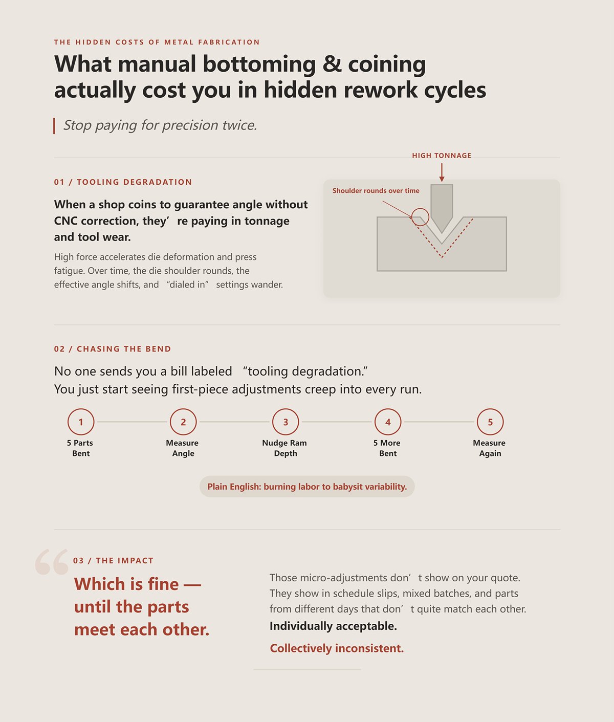
When a shop coins to guarantee angle without CNC correction, they’re paying in tonnage and tool wear. High force accelerates die deformation and press fatigue. Over time, the die shoulder rounds, the effective angle shifts, and “dialed in” settings wander.
No one sends you a bill labeled “tooling degradation.” You just start seeing first-piece adjustments creep into every run. Five parts bent. Measure. Nudge ram depth. Five more. Measure again.
That’s what we call “chasing the bend” — repeatedly adjusting to hit target angle. Plain English: burning labor to babysit variability.
Those micro-adjustments don’t show on your quote. They show in schedule slips, mixed batches, and parts from different days that don’t quite match each other. Individually acceptable. Collectively inconsistent.
Which is fine — until the parts meet each other.
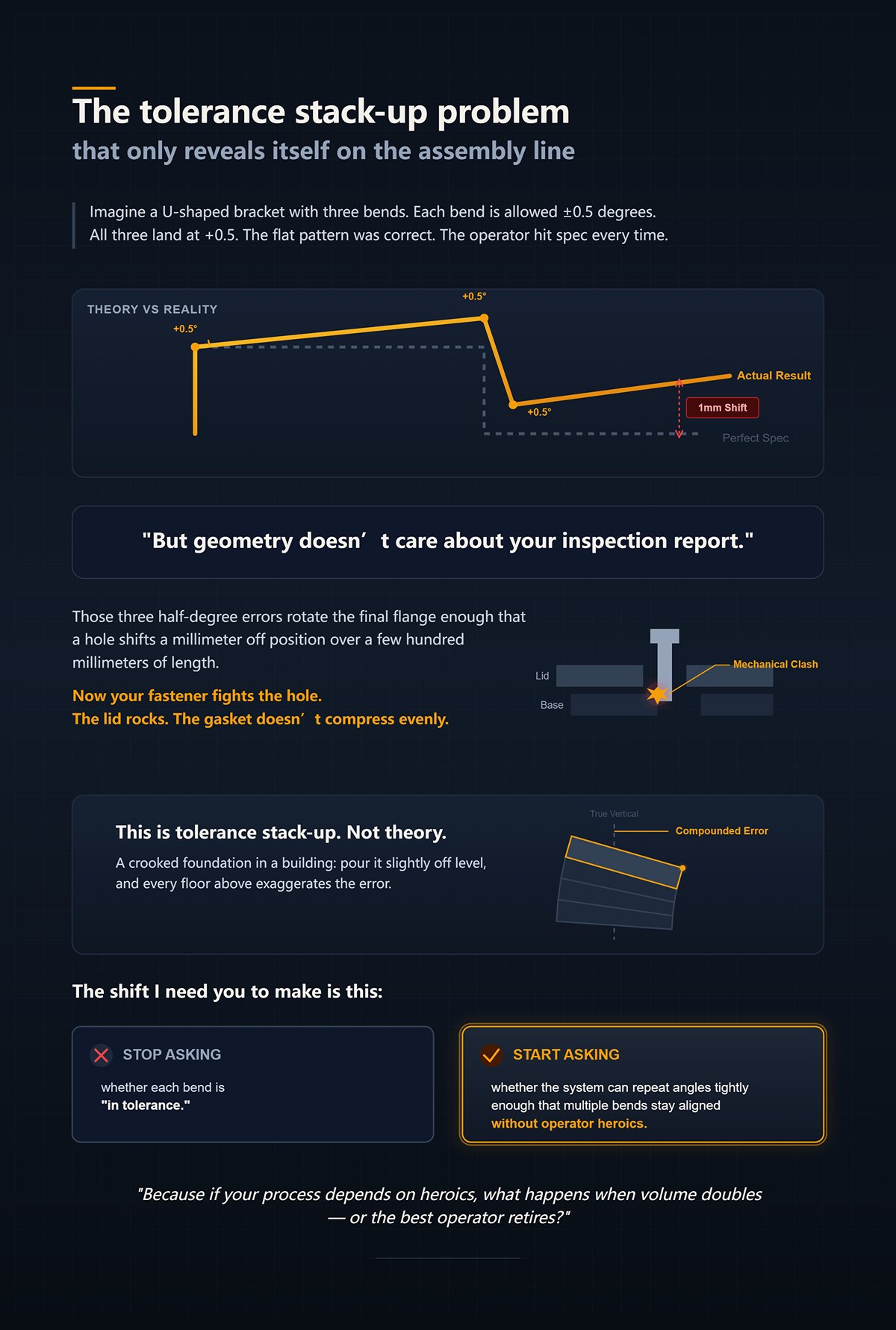
Imagine a U-shaped bracket with three bends. Each bend is allowed ±0.5 degrees. All three land at +0.5. The flat pattern was correct. The operator hit spec every time.
But geometry doesn’t care about your inspection report.
Those three half-degree errors rotate the final flange enough that a hole shifts a millimeter off position over a few hundred millimeters of length. Now your fastener fights the hole. The lid rocks. The gasket doesn’t compress evenly.
This is tolerance stack-up. Not theory. A crooked foundation in a building: pour it slightly off level, and every floor above exaggerates the error.
The shift I need you to make is this: stop asking whether each bend is “in tolerance.” Start asking whether the system can repeat angles tightly enough that multiple bends stay aligned without operator heroics.
Because if your process depends on heroics, what happens when volume doubles — or the best operator retires?
A four-bend enclosure ran clean for three months. Same program. Same operator. Then a new coil lot showed up. Yield strength crept up just enough that springback doubled what the model predicted. Every single bend still measured within the print’s ±1 degree.
And the assembly line jammed.
That’s where we pick up: individual bends “good,” assemblies bad. So what process actually prevents that?
It starts with the machine’s architecture. Not the paint color. Not the brand decal. The architecture. Because the frame stiffness, drive system, feedback method, and control logic determine whether angle is a guess corrected by a human—or a controlled variable measured in real time.
A crooked foundation in a building doesn’t announce itself on day one. It shows up when you try to hang doors on the third floor. The press brake is your foundation. You want it poured level the first time.
Walk into a basic hydraulic brake shop at 7:30 a.m. First piece of the day: bend, measure, adjust ram depth, bend again. The oil is still warming; viscosity changes response. That’s not operator incompetence. That’s physics.
Hydraulic systems rely on fluid pressure to position the ram. Temperature affects viscosity. Viscosity affects flow. Flow affects ram position under load. You can compensate—but you are compensating.
Servo-electric drives are different. Ball screws or belt-driven systems position the ram mechanically, with encoder feedback measuring position directly. No fluid compressibility. No temperature drift in the same way. When you command 12.384 mm of stroke, you get it.
Why does that matter to you?
Because every first-piece adjustment is time, and every adjustment during a run is variation between early and late parts. On a 200-piece batch, if you lose five parts dialing in each setup—and you run ten setups a week—that’s fifty parts of pure non-value. Multiply that across months. That’s your “cheap” quote evaporating in scrap and labor.
Now let’s stress-test this.
Bottom bending on a hydraulic press can control springback well. It forces the material into the die, reducing angle variability. For many simple brackets, it works 80% of the time. I’ve run thousands that way.
But look closely at what makes that possible: tonnage.
Bottoming can require roughly four times the force of air bending. Coining can take five to ten times. That force loads the frame, deflects the bed, and accelerates die wear. As tooling shoulders round off, the effective bend angle shifts. You don’t see it in one part. You see it across weeks.
We call that “frame float” — subtle deflection under load that changes effective angle. Plain English: the machine bends differently at 20 tons than it does at 60.
If your part family includes thin aluminum one day and high-strength steel the next, that variability compounds. So ask yourself: is your provider’s machine correcting for load and position in real time, or are they muscling material into shape and hoping yesterday’s settings still hold?
| Section | Content |
|---|---|
| Morning in a Hydraulic Shop | At 7:30 a.m., the first part requires bend, measure, adjust ram depth, and bend again. Oil temperature affects viscosity, which changes system response. This is physics, not operator incompetence. |
| How Hydraulic Systems Work | Hydraulic systems rely on fluid pressure to position the ram. Temperature affects viscosity, viscosity affects flow, and flow affects ram position under load. Compensation is required to maintain accuracy. |
| How Servo-Electric Systems Work | Servo-electric drives use ball screws or belts with encoder feedback to position the ram mechanically. No fluid compressibility and minimal temperature drift. Commanding 12.384 mm of stroke delivers exactly that. |
| Why It Matters | Every first-piece adjustment costs time. Adjustments during production create variation between early and late parts. Losing five parts per setup across ten setups per week results in fifty wasted parts—compounding into scrap and labor losses over time. |
| Bottom Bending on Hydraulic Presses | Bottom bending can control springback by forcing material into the die, reducing angle variability. Effective for many simple brackets about 80% of the time. |
| Force Requirements | Bottoming may require four times the force of air bending. Coining can require five to ten times the force. Increased tonnage loads the frame, deflects the bed, and accelerates die wear. |
| Tooling and Frame Impact | As tooling shoulders wear, effective bend angle shifts gradually. Frame deflection under varying loads (“frame float”) changes bending behavior—20 tons vs. 60 tons produces different results. |
| Material Variability | Switching between thin aluminum and high-strength steel compounds variability. The key question: Is the machine correcting for load and position in real time, or relying on force and previous settings? |
A supplier once advertised ±0.1 mm repeatability. Sounds surgical.
Then we measured angle, not backgauge position. Angle drifted nearly a degree when material thickness varied by 0.003 inches between coil lots. The ram hit the same depth every time. The angle changed anyway.
Position repeatability is not angle repeatability.
Active angle measurement systems use laser or contact sensors to read the actual bend angle during forming and adjust ram depth dynamically. The machine doesn’t assume springback. It measures it. On every part.
Without that, “±0.1 mm” refers to how consistently the ram moves—not whether the flange ends up at 90.0 degrees.
Remember the earlier example: three bends each at +0.5 degrees. Now imagine four bends drifting +0.7 because the material lot changed. Geometry multiplies error. A few tenths per bend becomes a millimeter at the far edge. Holes miss. Lids rock.
Some will argue coining eliminates springback. True. By plastically crushing the material, you nearly remove elastic recovery. But you pay in tonnage—often up to ten times air bending—and that restricts material thickness, increases crack risk in high-strength alloys, and punishes tooling life. It’s brute force precision.
Active angle measurement gives you precision without brute force.
So when a shop claims tight tolerance, ask the blunt question: are you measuring angle during the bend, or are you trusting last week’s test coupon?
If they aren’t closing the loop, they aren’t controlling the variable that actually matters.
Air bending gets a bad reputation because it’s sensitive. Change thickness. Change yield. Angle shifts.
But sensitivity isn’t the enemy. Uncontrolled sensitivity is.
Modern CNC controls store material libraries: thickness, tensile strength, tooling geometry, punch radius, die opening. The control calculates target penetration depth based on predicted springback. Then, with angle measurement feedback, it refines that prediction on the fly.
That’s not guesswork. That’s iterative control.
Imagine a U-shaped bracket with three bends, then add a fourth flange. If the first bend is corrected automatically to 90.0 degrees under real material conditions, the second bend starts from a known geometry. Error doesn’t cascade. The foundation stays level.
Contrast that with manual air bending on a basic brake. Operator bends, measures, tweaks. Maybe the first ten parts are perfect. Then material hardness shifts mid-coil. Without real-time correction, drift creeps in. By the time inspection catches it, you have a mixed batch.
In the shop we call that a “split lot” — parts from the same run that don’t match each other. Plain English: assembly roulette.
Algorithmic air bending, paired with angle feedback, prevents split lots by making each part self-correcting. That’s why advanced CNC providers can run thinner tooling inventories, switch materials faster, and still ship consistent geometry.
And that’s the hinge point: machine architecture determines whether repeatability is baked into the process or dependent on operator vigilance.
If the hardware can’t guarantee angle under real-world variation, no amount of individual-bend inspection will save your assembly.
So before you judge a quote by price per bend, ask a harder question: what exactly is controlling the angle when steel doesn’t behave the way the brochure said it would?
You want to know how to verify a supplier’s real-time control and assembly consistency?
Don’t start with the control screen. Start with the tool rack.
I’ve walked into shops with shiny CNC brakes and laser angle sensors, and then looked behind the machine to find three beat-up V-dies and a handful of generic punches. That tells me more than any brochure. Because closed-loop angle control can correct springback, but it cannot compensate for worn shoulders, mismatched tool heights, or geometry the shop doesn’t physically own.
We call that “making do” — forcing available tools to approximate the job. Plain English: improvisation dressed up as capability.
Look closely at their tooling library. Is it organized by die opening, punch radius, and application? Are tools precision-ground to standardized heights, or are shims stacked like poker chips to level them? Standardized height matters because the CNC control assumes a known reference. If every setup requires manual Z-axis tweaking to account for mixed tool heights, you’ve already lost repeatability before the first bend.
This is where batch efficiency lives or dies.
A deep, well-maintained tooling library lets a shop run angle-corrected air bending the way it was designed: predicted depth, measured angle, automatic compensation. A thin library forces workarounds that multiply setup time, introduce variation, and quietly shift cost downstream into assembly. And that’s the false economy you’re trying to avoid.
So how do you tell the difference between a shop that owns precision and one that rents the appearance of it?
Picture a simple enclosure: four sides, lid on top. A lid rocks on one corner.
The print says 90 degrees ±0.5. Inspection signed off. Yet the lid rocks.
Now measure the actual bend angles across the batch. You’ll often find variation not from the machine stroke, but from the die shoulders. Standard, non-ground V-dies can vary a few thousandths in height from section to section. That doesn’t sound like much. But on air bending, angle is a function of punch penetration into the die opening. Change the effective die geometry by even 0.002–0.003 inches and you can shift angle by tenths of a degree.
Stack that across four bends and your enclosure twists.
Precision-ground tooling is machined and finished to tight tolerances in both angle and height. Sections are interchangeable. When paired with sectionalized, quick-change clamping, the operator doesn’t re-indicate or shim every time. The control’s programmed depth corresponds to real geometry, not approximated geometry.
Stop paying for “±0.5 degree” claims without asking how they maintain die consistency over time. Die wear rounds the shoulders. Rounded shoulders effectively widen the V-opening. Wider V means less resistance, more springback, larger angle. You won’t see it in a single part. You’ll see it as a drift across weeks.
Advanced providers track tool life and rotate or regrind dies before wear becomes angle variability. Commodity shops run them until the parts complain.
Which shop do you think protects your assembly better?
Imagine a U-shaped bracket with three bends, then add a return flange that tucks back under the part. Now you need a gooseneck punch — relieved geometry that clears the formed leg during the final bend.
If the shop doesn’t own that punch, they have three options: redesign your part, sequence bends in a compromise order, or attempt the bend with a straight punch and limited depth.
None of those are neutral choices.
In one hypothetical but common scenario, the operator flips the bend order to avoid collision. That changes how accumulated tolerance stacks. The first flange, previously corrected by angle feedback, is now influenced by prior bends that weren’t fully stabilized. Your final dimension shifts by a millimeter at the far edge. The print may still pass per-feature inspection. Assembly won’t forgive it.
We call that “tool boxing” — squeezing a part into the closest available tooling. Plain English: forcing geometry to fit inventory instead of fitting inventory to geometry.
Deep tooling libraries aren’t about bragging rights. They’re about eliminating compromise. Specialty punches, narrow V-dies for tight inside radii, hemming tools, offset tools — each one prevents a workaround that would otherwise introduce either extra setups or geometry distortion.
If they don’t own the punch your geometry requires, you are paying for improvisation instead of precision. And improvisation is slow.
So the next question is obvious: even if they own the right tools, how much does it cost you every time they have to touch them?
I once compared two shops quoting the same 150-piece bracket family. Shop A charged 20% more per hour. Shop B was the “local bargain.”
Shop B set up at the machine. Load tools. Adjust heights. Bend first piece. Measure. Tweak. Scrap two. Try again. Forty-five minutes before stable production.
Shop A sent me screenshots from their offline programming system. Bend sequence validated digitally. Tonnage calculated against material database. Collision checks done. Tool list printed before the operator walked to the brake. With standardized-height, quick-change tooling staged in a waist-high cart, setup was under fifteen minutes. First piece was within correction range of the angle sensors.
But look closely at what makes that possible: tonnage.
Offline software calculates required force for each bend based on material thickness, tensile strength, die opening, and bend length. If the predicted tonnage approaches machine limits, the sequence changes before metal is touched. That prevents frame deflection and mid-run adjustment. It also protects tooling from overload that would accelerate wear and reintroduce angle drift.
The cheaper hourly rate evaporated in setup labor and five scrapped first-article parts per configuration. Over multiple part numbers, Shop A’s higher rate produced a lower true per-piece cost because they weren’t relearning the job every time.
This isn’t about CNC versus hydraulic. A disciplined hydraulic shop with standardized tooling and offline planning can outperform a sloppy CNC shop. The dividing line is operational maturity — whether the provider has invested in tooling depth, standardized heights, digital validation, and organized staging.
And that’s your practical test.
Don’t ask, “Do you have angle measurement?” Ask to see their tool library. Ask how they stage tools per job. Ask whether programming happens at the control or before the shift starts. Ask how they track die wear.
The answers sort providers into tiers fast.
Because once you see how they handle tooling and setup, you can predict whether your batch will behave like a controlled process — or like an experiment repeated 150 times.
A purchasing manager once showed me three quotes for the same 3 mm stainless enclosure. One shop was 18% cheaper. On paper, same material, same bends, same quantity.
But look closely at what separates them: not the hourly rate, not the brand of brake — the tooling maturity behind the brake.
If you want to systematically compare providers, stop asking what machine they own. Ask three things instead. How many precision-ground punches and dies do they stock by height standard? Do they program bends offline with tonnage calculation before setup? Do they track tool wear and rotate dies by schedule instead of waiting for angle drift?
Those answers will sort your options into three tiers fast.
Now let’s put them head-to-head.
Picture a 50-piece run of a simple L-bracket. One bend. Mild steel. ±1 degree tolerance. No downstream cosmetic requirement.
A manual or basic NC brake in the 80–125 ton range can bottom-bend that all day. Bottoming — forcing the punch into the die until the material contacts both die shoulders — gives you mechanical angle repeatability without fancy sensors. It also takes roughly four times the force of air bending. On a short 200 mm bend in 3 mm steel, that’s manageable on a modest machine.
Setup is quick. Tooling is basic. No offline programming overhead to amortize across tiny volume.
That’s where the legacy shop wins.
We used to call this “one-hit gravy” — a simple bend you can run profitably with minimal setup. Plain English: uncomplicated geometry that doesn’t justify sophisticated infrastructure.
But stretch that same part to 1200 mm long and hold ±0.5 degree across the length. Now deflection matters. Now material variation matters. Without angle measurement or crowning control, the operator chases angle with shims and test hits. Scrap creeps in. Labor creeps in.
Or imagine a 12 mm plate bracket requiring 280 tons over a long bend. Many electric servo brakes top out structurally around 300 tons. A heavy hydraulic in a local shop might handle it without blinking. For thick plate, high-tonnage work, the “basic” provider can be the only rational option.
So yes — manual bottoming makes financial sense when the geometry is simple, the tolerance forgiving, the bend count low, and the tonnage either modest or brutally high.
Change any one of those variables and the math starts to shift.
Now take a 500-piece batch of medium-complexity parts. Four bends. 2 mm aluminum. Moderate tolerances.
A servo-electric CNC brake cycles fast. Acceleration and deceleration are tight. Energy use is lower. Backgauges reposition quickly. On thin material under 125 tons, that speed compounds over hundreds of cycles.
If setup is standardized — common tool heights, quick-change clamping — the first-piece time shrinks. That’s real money at volume.
But look closely at what makes that possible: tonnage.
Servo-electric systems shine in lower force ranges. Push them toward their structural ceiling and you lose margin. Frame deflection increases. You slow the cycle to stay safe. Some platforms simply aren’t built for sustained 300+ ton work. When your part mix creeps thicker, the advantage narrows.
There’s another ceiling buyers miss.
Many CNC hubs invest in the machine but keep a shallow tool library. Enough standard punches and V-dies to cover 80% of jobs. When your geometry needs a narrow V for a tight inside radius or a deep gooseneck for clearance, they improvise.
We used to call that “making do” — shop slang for bending with what you have instead of what you need. Plain English: forcing your design into limited tooling.
On simple, mid-volume work, that compromise may never show. On tighter assemblies, it’s the start of stacked error.
So the automated hub wins when volume rewards speed, tolerances are reasonable, and tonnage sits comfortably within the machine’s sweet spot.
Step outside that envelope and you start paying for the gap.
Imagine a U-shaped bracket with three bends, then add a return flange that tucks back under the part. Five bends total. Two critical dimensions reference opposite legs.
On paper, each bend holds ±0.5 degree.
Now run the tolerance stack. If three bends each drift +0.5 degree, the far leg shifts enough that a lid rocks on one corner. The print might pass per-feature inspection. Assembly won’t.
An engineering-first fabricator attacks that at the source. Active angle measurement reads the actual bend angle during forming and corrects ram depth in real time. Offline software calculates required tonnage per bend based on thickness, tensile strength, die opening, and bend length before the operator loads tools. Precision-ground, standardized-height tooling ensures the programmed depth corresponds to real geometry.
This is what we called “pouring it level” — fixing alignment at the foundation. Plain English: controlling the bend so downstream parts don’t absorb the error.
Yes, their hourly rate is higher. Yes, the machine costs more — often 50,000 to 150,000 and up versus a fraction for manual equipment.
But apply it to a 200-piece run where each bad enclosure forces 20 minutes of rework in assembly at loaded labor cost. Scrap five units due to accumulated angle drift and you’ve erased the savings from the cheaper quote.
Stop paying for the illusion that per-piece brake time is the dominant cost. In multi-bend, tight-tolerance parts, the dominant cost is failure propagation — how a small angular error multiplies across features and into assembly labor.
The premium is justified when bend count is high, tolerances interact, cosmetic standards matter, and downstream assembly is expensive or automated.
Which means the real comparison isn’t about machines at all.
It’s about matching part complexity, tolerance interaction, and tonnage demand to the provider’s tooling depth and control systems — and knowing how to verify that before you release the PO.
You want to know how to verify tooling maturity and control capability before you release the PO.
Good. Because the capability sheet is where most buyers get seduced.
A press brake brochure reads like a pickup truck ad: 100 tons, 10-foot bed, CNC backgauge, brand-name control. Shiny numbers. None of them tell you whether that shop can hold ±0.5 degree across a 1200 mm bend, three times in a row, on material that varies heat to heat. And that’s the difference between a part that assembles and one that gets “massaged” on your floor.
Treat the RFQ like an X-ray, not a handshake. You’re not checking how hard they can push. You’re checking how precisely they can stop.
What should you be looking for?
Stop paying for total tonnage as if it’s a precision metric.
A 100-ton machine with 10 feet between side frames sounds impressive until you remember the 60 percent rule: full tonnage is designed to be applied over roughly 60 percent of the bed length. That means about 6 feet. Apply that same 100 tons over a short, concentrated length and you’re not “more capable.” You’re deforming the bed and the tooling.
But look closely at what makes that possible: tonnage per unit length.
If a shop tells you “300 tons,” your next question is simple: how many tons per foot or per meter, and what’s the tooling rated for? Standard European-style tooling often caps around 100 tons per meter of line load. Push 30 tons over 200 mm and you’re at roughly 150 tons per meter. That’s 50 percent beyond the tooling’s comfort zone. The first article might look fine. The fourth part carries the dent.
Metric one: maximum allowable line load (tons per foot or meter) for both machine and tooling.
Metric two: documented deflection compensation method. Not “CNC controlled.” Ask whether they use active crowning and whether it’s manual, table-based, or automatically calculated from bend length and force. A machine can be rated within 0.0015 inches per foot of deflection and still vary angle across the bed if nobody compensates in real time.
Metric three: angle control method. Ram position control is not angle control. Do they use laser or mechanical angle measurement that reads the actual bend and corrects depth during the hit? Or is the operator making test bends and tweaking offsets?
We used to call shops that ignored line load “running it hot” — slang for pushing force where the machine or tool wasn’t meant to take it. Plain English: borrowing accuracy from tomorrow to get a part out today.
Now ask yourself: if they don’t volunteer these numbers, do they even track them?
Look closely at how they describe material capability.
“We can bend mild steel, stainless, and aluminum” tells you nothing. Every brake can bend something once. The question is whether they’ve dialed in springback behavior for the thickness and strength range you live in.
Springback is the elastic recovery after forming. It’s why 90 degrees on the screen doesn’t equal 90 degrees in the part. The variation isn’t random; it tracks tensile strength, grain direction, and die opening. A shop that regularly runs 2 mm 5052 aluminum will have stored correction factors, preferred V-openings, and known tonnage windows. A shop that “occasionally” runs it will be discovering those numbers on your order.
Ask for the thickness and grade range they run weekly, not occasionally.
If your part is 4–6 mm stainless and they primarily bend thin aluminum, you’re not buying capability. You’re funding experimentation. And if your job requires 280 tons over a long bend and their biggest brake is 100 tons, that’s not a pricing issue. That’s the wrong machine category.
We used to call that “horses for courses” — shop slang for matching the machine to the job. Plain English: don’t bring a light-duty brake to a heavy-plate fight.
Capability isn’t “can you bend it.” It’s “have you bent this family of material enough to predict it.”
So how do you make that prediction contractual instead of hopeful?
The first bad bend is never just the first bend.
Here’s the quiet problem: concentrated overload or poor crowning doesn’t always show up on part one. Tooling can take a hit and still produce something within tolerance. By part three or four, the die shoulder is bruised, the table has a faint witness line, and angles start drifting. Now your “approved” first article is irrelevant.
Stop accepting a first article clause that ends at dimensional sign-off.
Define it around process stability. Require that first article approval includes documented tonnage calculation per bend, die selection, and confirmation that line load stays within tooling rating. If they don’t know the tooling’s rated load, that’s your answer.
And clarify rework responsibility beyond piece one. If parts two through ten drift because the process wasn’t controlled, who pays? The disciplined shop will accept that risk because they know their load management and angle control are locked in. The gamble shop will push back.
We used to call the gamble approach “cut and pray” — slang for run it and hope it passes. Plain English: no closed-loop control, no safety net.
This isn’t about being adversarial. It’s about revealing whether their cost structure depends on you absorbing the variability.
Once you filter providers this way, something changes.
The conversation stops being “Who’s cheaper per hour?” and becomes “Whose system matches my part’s tolerance interaction, bend count, and tonnage demand?”
And that’s where the real comparison finally gets honest.
You don’t translate capability checks into protection with adjectives. You do it with triggers.
If true capability is controlled, repeatable process performance, then your RFQ has to require evidence of control — and define what happens when that control drifts. Not “CNC press brake, ±0.5°.” Write: active angle measurement with in-process correction; documented tonnage per bend; tooling line-load within manufacturer rating; rework at supplier cost for angle drift beyond X degrees after first-article approval. Now you’re not buying a machine. You’re buying a managed process.
The non-obvious part? When you specify control instead of hardware, the premium shop stops looking expensive. The gamble shop starts looking exposed.
So which tier actually matches your project?
Stop asking for 48-hour turnaround if you’re sending ornamental geometry.
Fast CNC brake shops can move quickly because their software pre-calculates bend sequence, collision clearance, and tonnage before the first sheet hits the bed. But that only works if your CAD file includes true material spec, grain direction, inside radii, and realistic tolerances. Leave those vague and they’re forced into test bends and operator judgment — the very variability you’re trying to avoid.
Imagine a U-shaped bracket with three bends. If you call out ±0.2 mm flange length but don’t state that the inside radius must be 1.5× thickness in 304 stainless, the shop has to choose a die opening. That choice shifts springback. That shifts leg length. Now “fast” means three trial hits and a shim under the backgauge.
We used to call incomplete prints “ghost chasing” — shop slang for hunting dimensions that move because the inputs were wrong. Plain English: your missing data becomes their setup delay.
So write your RFQ to require a bend deduction method declaration and simulation approval before cutting material. Speed from a controlled CNC provider is front-loaded thinking, not frantic pressing. Are you giving them what that speed depends on?
Look closely at where the math flips.
A local manual shop might quote 18 percent cheaper on 50 pieces. No active angle measurement. No offline programming. Just a skilled operator and a tape measure. For 50 parts, maybe that gamble doesn’t explode.
But run the numbers at 500.
Assume a conservative hypothetical: 5 bends per part, 30 seconds per bend cycle on a CNC with stored programs and angle correction. That’s 2.5 minutes of bending time. Add minimal adjustment because the first three hits auto-correct. Now compare that to a manual process adding even 20 seconds per bend for check-and-tweak. You’re at 4 minutes per part before you count rework.
Time is cost. Drift is cost. Assembly fallout is real cost.
But look closely at what makes the CNC stable at volume: tonnage management and angle feedback. Without active measurement, springback variation across a new coil lot can push you +0.5° per bend. Stack five bends and your last flange is off enough to fight a weld fixture. A lid rocks on one corner.
We used to call that “chasing the tail” — slang for adjusting the last bend to compensate for the first four. Plain English: compounding error that burns labor downstream.
Your contract term here is simple: angle tolerance verified by in-process measurement, not post-process sampling. And add a clause tying payment to batch-level conformance, not just first-article approval. At volume, the shop with closed-loop control often becomes the lowest true per-piece cost — because they’re not billing you in hidden assembly hours.
So where’s the real batch threshold for your part — 200 pieces, 2,000, 20,000?
This is where most teams get trapped.
Prototype at a flexible local shop. Production to a different “more automated” supplier. Re-qualify. Rebuild bend programs. Re-discover springback. Pay twice for learning.
Stop paying for the same mistake at two different hourly rates.
Advanced CNC providers with deep tooling libraries and stored bend data don’t just make parts; they accumulate correction factors by material, thickness, and die set. When your prototype moves to 5,000 pieces, they aren’t guessing again. They’re scaling a known process window.
Hydroforming will tempt you here — single-step forming, universal tooling, seconds-long cycles. For certain geometries, it’s brilliant. But if your part evolves, or tolerances tighten at production, you’re back to tool validation and process tuning. Press brake CNC with active angle control lets you adjust depth and sequence without new hard tooling every time design shifts.
We used to call shops that could carry data from proto to production “memory keepers” — slang for operations that learn once and charge once. Plain English: institutionalized process knowledge.
Your RFQ language should require program retention, documented bend parameters, and price protection tied to unchanged geometry and material spec. If nothing changes, neither does the price. If they can’t agree to that, they’re not confident their process is portable.
Here’s the crooked foundation problem: a bend that’s slightly off in prototype becomes structural misalignment at production scale. Fixing it later costs exponentially more than pouring it level the first time.
Match complexity and tolerance stack to control level. Match volume to process stability. Match scaling plans to data retention.
Do that, and the so-called premium CNC shop stops being a line-item luxury and starts looking like insurance you don’t have to file a claim on.
Now the only question left is this: are you buying bends — or are you buying predictable assemblies?


