

At 2:17 p.m., a lead operator tried to seat a 0.50-inch American tang into a 13 mm European-style clamp on a CNC brake. It wouldn’t lock. He tapped it. He swore at it. Then he asked why the “standard” punch from the catalogue didn’t fit his “standard” machine.
That PDF looked simple. Rows of punches. Rows of dies. Clean line drawings like a restaurant menu. Pick your profile, add to cart, move on.
Except your press brake isn’t hungry for shapes. It’s wired for a specific clamping DNA and a specific tonnage per inch. Ignore that, and the catalogue will hand you scrap bin donations with a smile.
A tooling catalogue is a compatibility test disguised as a brochure. It assumes you already know your machine’s clamping architecture, working length, maximum tonnage per inch, and bending method. It does not slow down to check your homework.
That’s the trap.
The layout encourages you to browse by geometry: 30-degree punch, gooseneck, hemming die, 1.000 V-opening, 0.062 inside radius. You start with the part in your head. The catalogue wants you to start with the machine under your feet.
If you don’t reverse that order, every page becomes a minefield. So what are you actually shopping for?
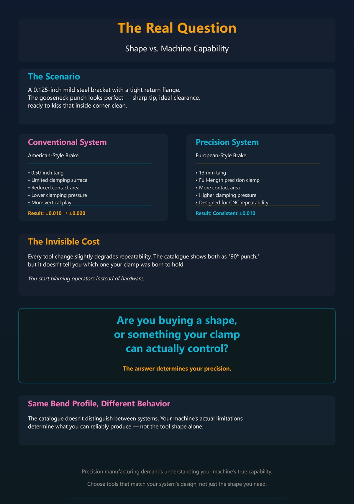
Picture a 0.125-inch mild steel bracket with a tight return flange. You flip to the gooseneck punches. There it is — perfect clearance, sharp tip, looks like it’ll kiss that inside corner clean.
But what clamp is on your brake?
If you’re running a conventional American-style system with a 0.50-inch tang and limited clamping surface, every tool change slightly degrades repeatability. That reduced contact area means less clamping pressure, more opportunity for vertical play. Swap tools enough times and your ±0.010 becomes ±0.020, and you start blaming operators instead of hardware.
Now compare that to a 13 mm European tang seated in a full-length precision clamp. More contact area. Higher clamping pressure. Designed for CNC repeatability. Same bend profile on paper. Completely different behavior in the machine.
The catalogue shows both as “90° punch.” It doesn’t tell you which one your brake was born to hold.
So are you buying a shape, or are you buying something your clamp can actually control?
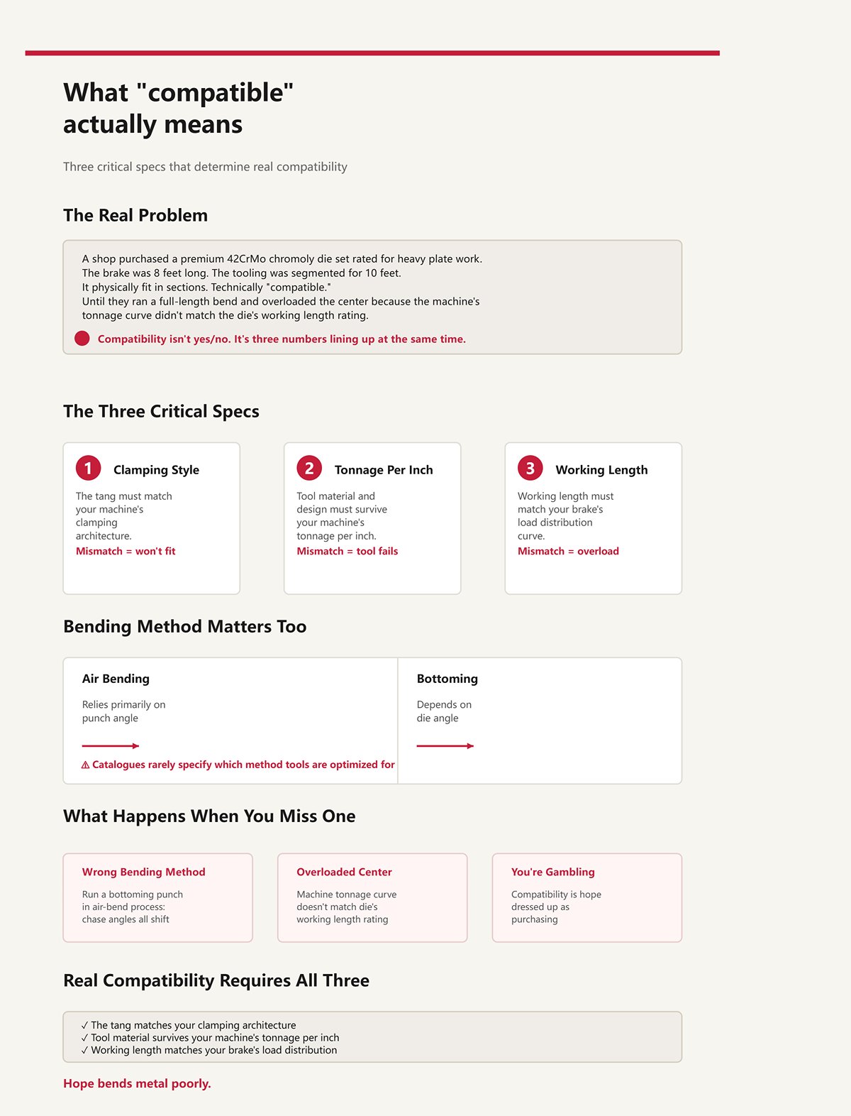
I once watched a shop buy a full die set rated for heavy plate work. Beautiful 42CrMo chromoly. Heat treated. Looked indestructible.
Their brake was 8 feet long. The tooling was segmented for 10 feet.
It physically fit in sections. Technically “compatible.” Until they ran a full-length bend and overloaded the center because the machine’s tonnage curve didn’t match the die’s working length rating. Compatibility isn’t a yes/no question. It’s three numbers lining up at the same time: clamping style, tonnage per inch, working length.
Miss one, and you’re gambling.
Then there’s bending method. Air bending relies primarily on punch angle; bottoming depends on die angle. Catalogues show profiles, but they rarely scream which method they’re optimized for. Run a bottoming punch in an air-bend process and you’ll chase angles all shift.
“Compatible” means:
Anything less is hope dressed up as purchasing.
And hope bends metal poorly.
Here’s where it gets seductive.
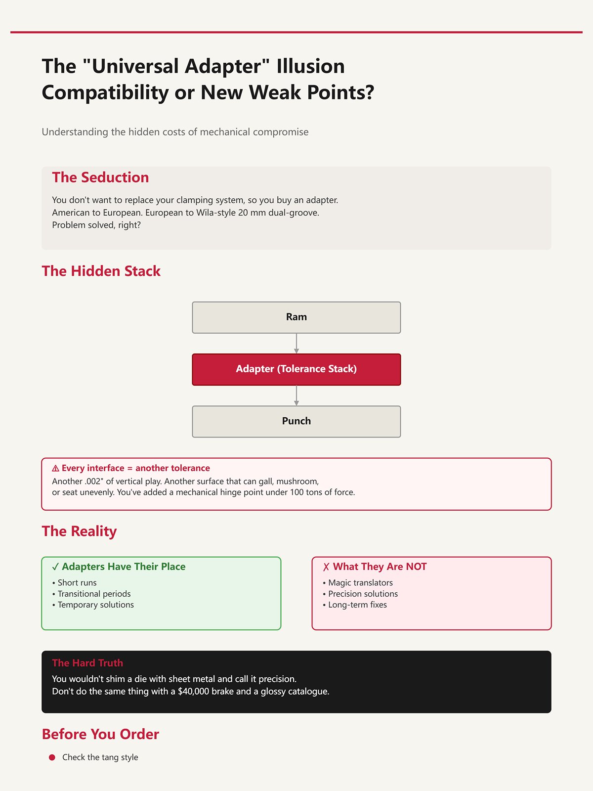
You don’t want to replace your clamping system, so you buy an adapter. American to European. European to Wila-style 20 mm dual-groove. Problem solved, right?
Now stack it in your head: ram → adapter → punch.
Every interface is another tolerance. Another chance for .002 of vertical play. Another surface that can gall, mushroom, or seat unevenly. You’ve added convenience — and a mechanical hinge point — between 100 tons of force and your bend line.
Yes, adapters have their place. Short runs. Transitional periods. But they are not magic translators. They are spacers under load.
You wouldn’t shim a die with sheet metal and call it precision. Don’t do the same thing with a $40,000 brake and a glossy catalogue.
Before you circle a single part number, walk to your machine. Check the tang style. Confirm the clamp type. Verify tonnage per inch and working length.
Start there.
A mechanic once tried to “make it work” by easing a 0.500-inch American tang into a 13 mm European-style precision clamp. On paper, 0.500 inch is 12.7 mm. Close enough, right?
He pulled the lever. It wouldn’t lock. So he tapped the tang with a brass hammer. After three taps, the top edge mushroomed about .015 inch. Now it wouldn’t fit back into his old American holder either. One shiny punch. Two machines. Zero usable tooling.
That’s what happens when you treat standards like suggestions instead of geometry.
You’re asking for step-by-step checks before ordering tooling. Good. Here they are, and they start with calipers, not catalogues:
You do that before you look at a single punch profile. Because the ram doesn’t care what shape you want. It cares what it can physically grip.
Measure first. Then decide.
Let’s get concrete.
An American-style punch typically has a 0.500-inch-wide tang with a flat back, retained by set screws or manual clamps that push horizontally. Contact area is limited—often a narrow strip along the tang face. That means clamping force concentrates in small zones. Fine for older mechanical brakes. Less forgiving for CNC repeatability.
A European-style tang is usually 13 mm wide, taller, with a defined shoulder and a safety groove near the top. It seats into a full-length precision clamp that pulls the tool upward into position. More surface engagement. More consistent vertical location. That’s why CNC machines favor it.
Promecam? Here’s where people get sloppy with terminology.
Original Promecam geometry includes a specific shoulder profile and safety notch location that mates with its dedicated clamp. The difference isn’t cosmetic. The distance from shoulder to groove might vary by a millimeter or two compared to generic “European” tooling. That millimeter determines whether the safety pin engages or misses entirely.
Miss it, and gravity is your only backup.
Now look at seating geometry.
American tools often hang slightly before set screws bite. You tighten, they shift .003 to .010 vertically depending on wear. European precision clamps are designed to eliminate that float by drawing the tool up into a ground reference surface.
Same punch angle. Same 30-degree tip. Completely different seating mechanics.
That difference shows up in bend consistency over a 96-inch run.
So when a catalogue says “European/Promecam compatible,” your job is to ask: which shoulder height? Which groove position? Which clamp pull-up direction? If you don’t verify those dimensions against your ram, you’re gambling with steel and hydraulics.
Don’t guess at interfaces measured in thousandths. Verify them.
I’ve walked into shops running high-end ground tooling—±0.01 mm height tolerance—and watched operators shim them with feeler stock because the clamp wasn’t a zero-alignment system.
That’s the dirty secret hiding behind the word “European.”
There is generic 13 mm European tang tooling. Then there is precision-ground tooling designed for self-seating hydraulic clamps. They are not interchangeable just because the tang width matches.
Suppose your brake has an older manual European-style clamp without automatic vertical alignment. You install precision-ground punches expecting perfect repeatability. But the clamp pulls slightly off-axis. Now that ±0.01 mm ground height is irrelevant because the tool is seating crooked by .05 mm.
You blame the tooling vendor.
The problem was mechanical DNA mismatch.
Even within “European,” shoulder radii, groove depths, and tang heights differ between manufacturers. Some are built around legacy Promecam geometry. Others around newer precision systems. If your clamp’s safety pin is positioned 2.0 mm higher than the groove on your new punch, it won’t engage. The tool may still bend parts—until it drops during a changeover.
Geography is a marketing label. Geometry is a mechanical fact.
So when someone says, “It’s European, it’ll fit,” your next question should be: fit which clamp, exactly?
If you can’t answer that with a dimension, stop the purchase order.
Now let’s address the shop-floor argument.
“I’ve run European top tools with American bottom dies for years. No disasters.”
They’re not wrong—under certain conditions.
The bottom die usually sits in a simple holder or die rail. As long as the die width matches the holder and the tonnage rating exceeds the load, mixing bottom styles is often mechanically irrelevant for basic air bending.
The danger shows up on the top.
Imagine half your bed loaded with American-tang punches in set-screw clamps and the other half with European-tang punches in retrofitted adapters. Under load—say 80 tons across 8 feet—the deflection characteristics differ. One section may seat .004 lower after tightening. The adapter stack may compress microscopically. Now your bend angle varies left to right.
You chase it with crowning adjustments.
Worse case? One section is rated for 20 tons per foot, another for 30. You bottom a 0.250-inch plate across both. The weaker section yields first. That’s how you create a permanent .003-inch vertical mismatch in a tool that used to be straight.
That mismatch never leaves. It just keeps making scrap.
And adapters? Every added interface is another tolerance stack. Ram → adapter → punch. You’ve added convenience — and a mechanical hinge point — between 100 tons of force and your bend line. Under repeated load, that stack can peen, gall, or shift.
Does mixing always explode the machine? No.
Does it quietly erode accuracy, repeatability, and tool life when you don’t account for load paths and seating differences? Every week.
Standardize your top clamping architecture across the full bed whenever possible. Match tang geometry exactly to the clamp. Confirm uniform tonnage ratings across all loaded segments.
Because once the ram comes down, physics—not marketing—decides what survives.
Lock the interface down before you ever worry about the bend angle.
A few winters back, a lead operator tried to seat a 0.125 mild steel job with a .472 V-die because “that’s what we always use.” He switched from air bending to bottoming to chase angle consistency on a ±0.5° print. Same punch. Same die. Different method. The ram hit bottom, tonnage spiked past 85 tons on a 6-foot section, and the die shoulders came out with a permanent .003 crown. That die now lives in the scrap bin rotation for “rough stuff.”
Nothing was wrong with the tang. Nothing was wrong with the clamp.
The method changed the load path.
Air bending floats the material between punch tip and die shoulders. Bottoming drives the punch nose into the material until it contacts the die angle. That difference alone rewrites your tooling requirements—clearances, radii, tonnage rating, even punch height. If you’re deciding which clamping standard to adopt long-term, you don’t start with brand. You start with which bending method your work mix demands 70% of the time. Choose wrong, and you’ll spend the next decade compensating for physics instead of controlling it.
Decide your dominant bending method before you standardize a single clamp.
Pick up two catalogues. One rates a 1.000 V-die at 30 tons per foot. Another lists a nearly identical profile at 24 tons per foot. Neither lies. One calculates rating at 90° in air bending. The other assumes near-bottom stroke conditions.
Bottoming is not “a little more pressure.” It is full contact along the die angle. The material is squeezed between punch and die faces, and any angular mismatch between punch and die—say 0.5°—doesn’t show up as springback variation. It shows up as localized stress.
Now picture a 90° punch mating with a die ground at 88.5°. In air bending, that angular difference barely matters; the material forms before full face contact. In bottoming, the punch shoulders try to wedge into a tighter cavity. Load concentrates at the upper die corners. That’s how you crack a hardened 42–48 HRC die that “should” have been within rating.
Catalogues assume ideal angle matching and perfect alignment. Your machine may achieve ±0.2°—but only with springback compensation dialed in and material batches behaving. Bottoming removes that forgiveness. Now die angle tolerance, punch angle tolerance, and ram parallelism stack directly into compressive stress at the die shoulders.
That’s why bottoming forces you toward tighter-ground dies, verified angle matching, and clamping systems that maintain true vertical pull-up. A .05 mm vertical seating error that was harmless in air bending becomes uneven face contact across segmented tooling in bottoming. One segment takes more load. One segment yields first.
If you plan to bottom routinely, buy tooling and clamps as if alignment error equals stress multiplier—because it does.
Walk to your brake and air bend 0.125 A36 over a 1.000 V-opening with a sharp 0.031 punch tip. Measure the inside radius. You’ll read roughly 0.156 to 0.170 depending on material batch.
Not 0.031.
In air bending, the inside radius is primarily a function of the V-die opening—commonly about 16% of V-opening for mild steel. The punch tip only needs to be sharp enough to avoid flattening the radius prematurely. It does not “create” the inside radius unless you bottom.
I’ve watched shops chase tighter inside radii by ordering 0.015 sharp punches while still using a 1.000 V-die. They were solving the wrong variable. The die opening was dictating the radius all along.
Now flip to bottoming. The punch nose radius is forced into the material until it conforms to the die angle. In that case, the punch radius becomes the controlling geometry. Same tooling profiles on paper. Completely different governing dimension once you change method.
This is where the catalogue sabotages the naïve buyer. It lists punch tip radii as if they’re always decisive. They aren’t. In air bending, your V-opening choice controls inside radius, tonnage per foot, and minimum flange length. In bottoming, punch radius and die angle matching dominate.
So when you standardize tooling, ask yourself: are we primarily controlling radius with die selection or with punch geometry? Your answer determines whether you invest in a broad die library or a tighter punch-radius inventory.
Don’t order sharp punches to fix a die problem.
Imagine a fixed-height punch system—say 5.984 overall height, common across goosenecks and acute punches. That uniform height lets a hydraulic clamp pull every segment to the same reference without shimming. Setup time drops. Stage bending becomes predictable.
Now load a 2.000 V-die under that punch to bend 0.250 plate in air. Your daylight disappears fast. If your open height is marginal, the ram may bottom out mechanically before you ever reach calculated tonnage. Or worse, the punch shoulder collides with the die shoulders because the punch was never intended for that wide a V.
V-opening isn’t just about radius and tonnage. It sets penetration depth for a given angle. Wider V means deeper punch travel to reach 90°. Deeper travel means more exposure to ram deflection, more demand on crowning, and greater risk of non-parallel contact if your clamping DNA isn’t truly self-seating.
I’ve measured angle variation of 0.4° across 96 inches simply because a shop switched from a 0.472 V to a 0.630 V without recalculating penetration depth and verifying ram parallelism under load. Nothing “wrong” with the tools. The geometry changed the machine’s behavior.
Punch height matters the same way. Too short, and you stack risers—adding another interface between ram and punch. You’ve added convenience — and a mechanical hinge point — between 100 tons of force and your bend line. Too tall, and you sacrifice daylight needed for tall flanges or box parts.
Method dictates V-opening. V-opening dictates penetration. Penetration dictates required punch height and clamp rigidity. That chain determines whether your brake produces ±0.2° parts—or steady scrap bin donations.
Before you adopt a clamping standard or retrofit your brake, map your dominant material thicknesses, target radii, and bending method. Then calculate V-openings and penetration depths. Let those numbers tell you what punch heights and clamp precision you need.
Run the math before you run the ram.
A shop I walked into last winter had a 100‑ton, 10‑foot brake bending 0.236 chrome moly over a 1.890 V-opening. The operator was proud of it. “We’re only at 92 tons,” he said, pointing at the screen.
The machine was under its rating. The tooling was not.
If you’re going to choose a clamping standard that survives long-term, you don’t start with tang style or brand loyalty. You start with this math. V-opening dictates inside radius and tonnage per foot. Material tensile strength multiplies that tonnage. Bending method decides whether that number is a suggestion or a brick wall. Your clamp and tooling system have to survive the worst combination you routinely run — not the average Tuesday afternoon job.
So before you standardize anything, you answer one question: what is the highest tonnage-per-inch scenario your dominant bending method will ever see on this machine?
Miss that, and your “standard” becomes a liability. Run the numbers before you pick hardware.
Take 0.236 (6 mm) mild steel at 60,000 PSI tensile. The old rule says 8× thickness for air bending, so about a 1.890 V-opening. Baseline tonnage might land around 117 tons over 10 feet. Manageable on a 130‑ton brake. That’s where the rule came from — mild steel, predictable tensile, air bending.
Now swap the material to high‑tensile chrome moly. Same thickness. Same 1.890 V. The tensile multiplier jumps — roughly 2.0 versus mild. That 117 tons becomes 234 tons across the same length.
Nothing in the “8×” rule changed. The physics did.
There’s a common formula floating around: P = 650 × S² × L × (Tensile / 60,000) / V
S is thickness, L is bend length, V is die opening. The key term is that tensile ratio. If you bend something like Raex 500 — roughly 232,000 PSI tensile — you’re staring at nearly four times the force of mild steel for the same geometry. Four times. Your V-opening didn’t get narrower. Your machine didn’t get weaker. The stress inside the die sure did get higher.
And here’s where catalogues quietly betray you. They print V-opening charts assuming 60,000 PSI material. They might mention stainless at 1.5×. They rarely scream that modern abrasion-resistant plate can be 3×–4×. So you follow “8× thickness,” stay under your machine’s 150‑ton rating, and wonder why your 42–48 HRC die starts spider-cracking at the shoulders.
The rule didn’t account for material evolution. It assumed a genetic code your shop may no longer share.
If your dominant work is high-tensile, the 8× rule is not wrong — it’s incomplete. You either widen the V to drop tonnage per foot, or you upsize the brake and tooling to survive the multiplier. Those are the only honest options.
Don’t let a mild-steel chart size dies for a 200,000 PSI job.
Picture a part with a 0.472 flange requirement in 0.125 A36. The correct air-bend die per the 8× rule is a 1.000 V. Minimum flange length for that die is roughly 0.600–0.650 depending on punch nose and material.
But the operator doesn’t want to swap to a narrower die. He closes up to a 0.630 V already staged in the machine. Now the minimum flange drops closer to 0.400–0.450. The short leg forms. Job moves on. Everyone’s happy.
Except the tonnage per foot just climbed.
Air bending force is inversely proportional to V-opening. Shrink V, force rises. That same 0.125 mild steel over 1.000 V might need roughly 12–14 tons per foot. Over 0.630 V, you’re pushing north of 20 tons per foot. Same part. Same material. Different die. Different load path.
Now add real-world variables. Thickness tolerance +0.010. Tensile 75,000 instead of the 60,000 you assumed. Friction higher because mill scale wasn’t cleaned. A common industry practice is adding a 15,000 PSI safety margin to published minimum tensile. That alone can bump force noticeably. The comfortable 20 tons per foot becomes 24 or 26.
And if that bend is bottomed instead of air bent? You can be at four times the air-bend tonnage. I’ve seen air charts applied to bottoming jobs because the catalogue page looked similar. That’s not a rounding error. That’s how you turn a die into two pieces.
You avoided a tool change. You increased localized stress, reduced die life, and maybe exceeded what your clamp was designed to pull straight.
Don’t squeeze V-openings to save setup time unless you’ve recalculated force and flange limits for that exact material batch.
Here’s the one that cracks tooling without warning.
A 100‑ton brake bending a 36‑inch part at 30 tons total looks safe on the screen. You’re at 30% of machine capacity. No alarms. No drama.
But do the division.
Thirty tons over 36 inches is 0.83 tons per inch. Fine — if your die is rated for, say, 1.5 tons per inch in that V-opening.
Now change the scenario. Same 30 tons, but the part is only 12 inches long and centered. That’s 2.5 tons per inch. If the die’s rating for that narrow V is 2.0 tons per inch, you are overloading it — while the machine loafs along at 30%.
That’s the localized tonnage problem. Machines are rated in total tons. Tooling lives and dies by tons per inch.
Catalogues love printing maximum machine tonnage compatibility. They are quieter about per‑inch load distribution and die ratings at specific V-openings. A narrow V in hardened tooling might be rated dramatically lower per inch than a wide V in the same series. Exceed it, and the first sign is often a hairline crack at the die shoulder — then a sudden fracture mid-run.
And if your clamping system doesn’t pull uniformly — if one segment seats 0.05 mm lower — that segment takes more than its share. One inch sees 3.0 tons while the average says 2.5. That’s how a single segment becomes a scrap bin donation while the rest look pristine.
You can be under the machine’s 100‑ton rating and still destroy a die because one 12‑inch section exceeded its per‑inch limit. That’s not bad luck. That’s math ignored.
When you evaluate a catalogue, stop looking at total tonnage first. Ask: what is the die’s tons‑per‑inch rating at this V-opening, and how does that compare to my worst‑case material, thickness, length, and bending method?
Answer that in ink before you ever load the tool.
You’re staring at worst-case tons-per-inch numbers that can crack a die while the machine screen says you’re “only at 40%.” Good. That’s the right kind of paranoia.
Now here’s the move most shops miss: you don’t start a catalogue by looking at shapes. You start by building a compatibility matrix — four lines on paper:
Until those four are written down, the catalogue is a trap disguised as convenience.
A tooling catalogue is not a menu. It’s a genetic screening test. Your press brake has a clamping DNA and a load limit coded into iron and hydraulics. Any tool that doesn’t match that code will be rejected violently.
So how do you actually read the thing without donating tooling to the scrap bin?
I don’t care what brand name is on the side. I care about what’s under the ram.
Is it true European-style tang with a 13 mm seat and front-loading groove? American-style two-piece with a separate punch holder? Promecam profile with a specific shoulder width? Measure it. Don’t assume. I’ve seen a lead operator try to seat a 0.500 tang into a metric slot because “it’s basically the same.” It wasn’t. The clamp paid for it.
Clamping geometry determines how load transfers from ram to punch. A tight, full-contact tang spreads load. A quick-change system with a cam or wedge introduces a hinge point. You’ve added convenience — and a mechanical hinge point — between 100 tons of force and your bend line.
But what clamp is on your brake — and what is it actually rated per inch?
Not brochure rating. Real rating.
If your brake is 150 tons over 10 feet, that’s 15 tons per foot average — 1.25 tons per inch — if perfectly distributed. Now look at your worst case from earlier: narrow V, high tensile, 12-inch part centered. You might be pushing 2.5–3.0 tons per inch locally.
If your clamping system and punch holder are only comfortable at 2.0 tons per inch continuous, you’ve already chosen the weak link.
Write down your maximum safe tons per inch based on worst-case material and shortest bend length you run. If you don’t know it, call the machine builder and ask. Don’t guess.
You are defining the ceiling your tooling must survive. Do that before you compare a single punch profile.
Air bending, bottoming, coining — they are not cosmetic differences. They are different load paths.
Air bending gives you radius as a function of V-opening. Bottoming drives the material into die shoulders. Coining compresses it past yield through thickness. Each step up multiplies tonnage. You already saw what that does to tons per inch.
So ask yourself: what inside radius are you actually trying to hit?
If your prints call for a 0.062 inside radius in 0.125 material, and you plan to air bend, that radius is controlled mostly by V-opening — roughly 16% of V for mild steel as a starting point. That means your die choice is radius control first, punch nose second.
But if you’re bottoming to “lock in” angle, the punch nose radius becomes dominant, and tonnage spikes hard against the die shoulders.
Different method. Different stress map. Same catalogue page.
Catalogues list punch profiles by tip angle and nose radius like they’re fashion options. They aren’t. They are structural decisions that determine whether your clamp sees smooth distributed load or concentrated compressive shock.
Define bending method and target radius in ink. Then eliminate every punch and die combination that forces you into a higher tonnage method than your clamp can tolerate.
Don’t let a pretty sectional drawing talk you into a load case your machine DNA can’t survive.
Here’s where most experienced operators get complacent.
The chart says 8× thickness. You nod. You’ve done it for 15 years.
But that chart assumes about 60,000 PSI tensile unless clearly stated otherwise. You already saw what happens at 200,000+.
So when the catalogue recommends, say, a 1.000 V for 0.125 material, that’s a geometry suggestion — not a survival guarantee.
Run the tonnage formula with your actual tensile. If your dominant material is 90,000 PSI, multiply accordingly. If you occasionally bend something north of 180,000, run that too. Use the worst case.
Then compare:
All three must agree.
If the die is rated for 2.0 tons per inch at 1.000 V, and your worst-case math says 2.4, that die is not “close.” It is wrong.
This is where the compatibility matrix does its work. You are not asking “Will it bend?” You are asking “Will it survive my worst job on my shortest part in my hardest material?”
Don’t let a mild-steel V chart size tooling for high-tensile reality.
| Step | Title | Key Actions | Critical Considerations | Required Checks |
|---|---|---|---|---|
| Step 1 | Reverse-engineer your machine’s clamping type and maximum tonnage per inch | Identify actual clamping system (European tang, American two-piece, Promecam, etc.). Physically measure geometry. Determine real tons-per-inch capacity. Calculate worst-case local tonnage based on shortest bend length and highest tensile material. | Clamping geometry determines load transfer. Quick-change systems may introduce hinge points. Brochure ratings are not sufficient. Localized loads can exceed average machine ratings. | Confirm actual clamp type and dimensions. Calculate maximum tons per inch under worst-case conditions. Verify clamp and holder continuous rating. Contact machine builder if necessary. |
| Step 2 | Define your bending method and target radius before looking at punch profiles | Decide on bending method (air bending, bottoming, coining). Define required inside radius from print. Eliminate tooling combinations that exceed safe tonnage. | Each bending method creates different load paths and tonnage requirements. Air bending radius depends mainly on V-opening. Bottoming and coining significantly increase tonnage. Punch nose radius becomes dominant in bottoming. | Confirm bending method in writing. Determine target inside radius. Verify tooling does not force higher tonnage than clamp capacity. |
| Step 3 | Cross-check the catalogue’s V-opening recommendations against your material’s tensile strength | Review catalogue V-opening suggestions. Recalculate tonnage using actual material tensile strength. Compare calculated tons per inch to die and clamp ratings. | Standard charts often assume ~60,000 PSI tensile. High-tensile materials dramatically increase tonnage. Geometry suggestions are not survival guarantees. | Calculate worst-case tons per inch. Confirm die rated capacity at selected V-opening. Ensure calculated tonnage does not exceed die or clamp safe limits. |
Sometimes the matrix says no to everything on the page.
Long bed. High tensile. Tight radius. Short flange. And a clamp system that wasn’t designed for modern abrasion-resistant plate.
You can play games — narrower V, staged bending, creative sequencing. Or you can admit the truth: the standard series wasn’t built for your load case.
That’s when you call technical support and say, clearly:
“My machine clamp is rated at X tons per inch. My worst-case bend is Y material at Z thickness over N inches. I need a die and punch profile that survives that without exceeding A tons per inch.”
Now you’re speaking their language.
Maybe the answer is a wider body die with higher per-inch rating. Maybe it’s a custom hardened grade. Maybe it’s a reinforced holder that matches your tang but spreads load deeper into the ram.
Or maybe the honest answer is that your machine is the limiting gene in the system.
That’s the lens I want you to carry forward: every tooling decision is a load-path decision. The catalogue is raw genetic data. Your job is to filter it through clamping geometry, bending method, tensile reality, and worst-case tons per inch before metal ever touches metal.
If you don’t build that matrix first, you’re not choosing tooling.
You’re gambling with force you can’t see.


