
At 4:37 p.m., we were stacking polished 5052 panels that looked perfect under shop lights. By 5:10, in sunlight, every bend line showed a faint, zipper-like scar from the lower die. Twenty-four panels at $202.50 each. $4,860.00 straight into the scrap rack because we trusted masking tape to “protect” a $38,000 job.
I didn’t change tape brands after that. I changed how I thought about what sits between the ram and my profit margin.
Most shops treat press brake film like shop rags—cheap, replaceable, good enough until it tears. I did too. A roll of masking tape costs lunch money; a strip of PVC wrap looks clean and feels slick. The logic seems airtight: if the die can’t touch the part, the part won’t scratch.
But that logic ignores what 60 tons of force does in a 1/8-inch contact zone. Under load, the brake doesn’t “rest” on the film. It compresses it, thins it, and pushes it sideways. What starts as a barrier turns into a conveyor belt, dragging grit and die imperfections straight across polished aluminum.
If the material between the part and the die is deforming unpredictably, are you protecting the surface—or just relocating the damage?
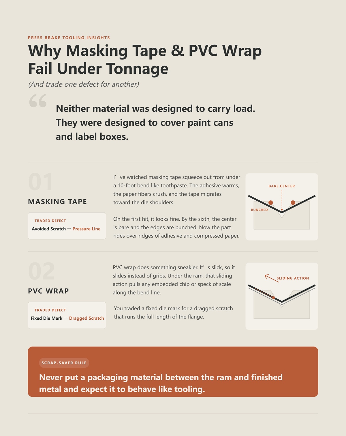
I’ve watched masking tape squeeze out from under a 10-foot bend like toothpaste. The adhesive warms, the paper fibers crush, and the tape migrates toward the die shoulders. On the first hit, it looks fine. By the sixth, the center is bare and the edges are bunched. Now the part rides over ridges of adhesive and compressed paper.
So the scratch you were avoiding becomes a pressure line from uneven thickness.
PVC wrap does something sneakier. It’s slick, so it slides instead of grips. Under the ram, that sliding action pulls any embedded chip or speck of scale along the bend line. You traded a fixed die mark for a dragged scratch that runs the full length of the flange.
Neither material was designed to carry load. They were designed to cover paint cans and label boxes.
Scrap-Saver Rule: Never put a packaging material between the ram and finished metal and expect it to behave like tooling.
Run the math the way a foreman does at 6:00 p.m., not the way purchasing does at 9:00 a.m.
Suppose you’re bending 200 pre-coated steel panels a week, profit margin $18 per part. If “good enough” protection causes just 3% to be rejected for cosmetic damage, that’s six parts. $108 in margin gone this week. Over a year, that’s $5,616.
Now price high-grade urethane die film for that same brake. Even if it runs you a few thousand dollars annually, the break-even scrap rate is shockingly low—often under 2% for cosmetic-sensitive work.
The tipping point isn’t dramatic. It’s quiet. A panel here. A rework there. A customer asking for a discount because “the finish isn’t consistent.”
When did we decide that losing finished parts was cheaper than upgrading the layer that protects every single bend?
I’ve paid to have dies polished to a mirror. They looked like chrome. First run on anodized aluminum, and we still saw hairlines.
Because polish doesn’t change pressure. The brake concentrates force along two narrow shoulders of the V-die. Even a flawless surface will micro-gall—microscopic material transfer between die and part—especially with softer alloys. Add one invisible speck of shop dust, and that speck becomes a cutting tool under load.
Bare, polished tooling removes one variable: surface roughness. It doesn’t remove contamination. It doesn’t distribute force. It doesn’t absorb shock.
We thought shine was protection. It was just aesthetics.
If the die finish can’t change the physics of contact stress, what can?
On a 10-foot brake running 0.125-inch 5052, we were forming a 90 with roughly 60 tons across the length. Masking tape split on the third hit. PVC wrinkled and polished the die shoulders into the part. Then we laid in a 90-durometer urethane strip—proper die film, not hardware-store plastic—and ran the same program.
At peak tonnage, you could see it compress. Not extrude. Not shear. Compress.
And when the ram lifted, it came back to thickness.
That rebound is the whole story. The brake delivers force in a narrow line along the die shoulders. If the material in that line yields—meaning it permanently deforms—you’ve lost thickness, lost uniformity, and invited metal-to-metal contact. If it has memory—elastic recovery—it absorbs the hit and returns, ready for the next cycle. That’s not packaging behavior. That’s load-bearing behavior.
Scrap-Saver Rule: If the layer between your part and the die does not elastically recover after full tonnage, it is not protection—it is pre-scrap.

Freeze the moment the punch reaches bottom of stroke.
Steel is yielding at the bend line. The die shoulders are concentrating force into roughly an eighth-inch contact zone. The barrier in between has two options: flow or deflect.
Masking tape flows. The paper fibers crush, adhesive softens from frictional heat, and the material migrates sideways. That migration thins the centerline. On the sixth part, you’re effectively bending on bare steel with adhesive ridges at the edges.
Urethane—when specified correctly—deflects instead. Under punch penetration, it compresses and forms a temporary female die. I’ve watched it wrap the sheet around the punch nose, conforming just enough to support the bend without imprinting the die edge. That’s not passive cushioning. That’s geometry changing under load.
But here’s the catch most sales reps won’t say out loud: urethane only “activates” if you actually load it. Too shallow a penetration, too conservative on tonnage, and it sits there like a stiff mat. No wrap. No redistribution. You think you’re protected, but the contact stress is still riding the die shoulders.
But that logic ignores what 60 tons of force does in a 1/8-inch contact zone. At sufficient load, high-grade urethane enters its elastic compression range and stores energy instead of surrendering thickness. When the ram retracts, that stored energy returns it to profile. That’s memory. That’s repeatability.
Different formulations matter. A softer 70-durometer strip will conform beautifully on light-gauge pre-painted steel but can abrade faster on heavy stainless. A harder 95-durometer piece survives higher tonnage but won’t wrap as aggressively on thin aluminum. The physics don’t change—only the operating window does.
So the real question isn’t “Does urethane work?” It’s “Is the durometer matched to the load you’re actually running?”
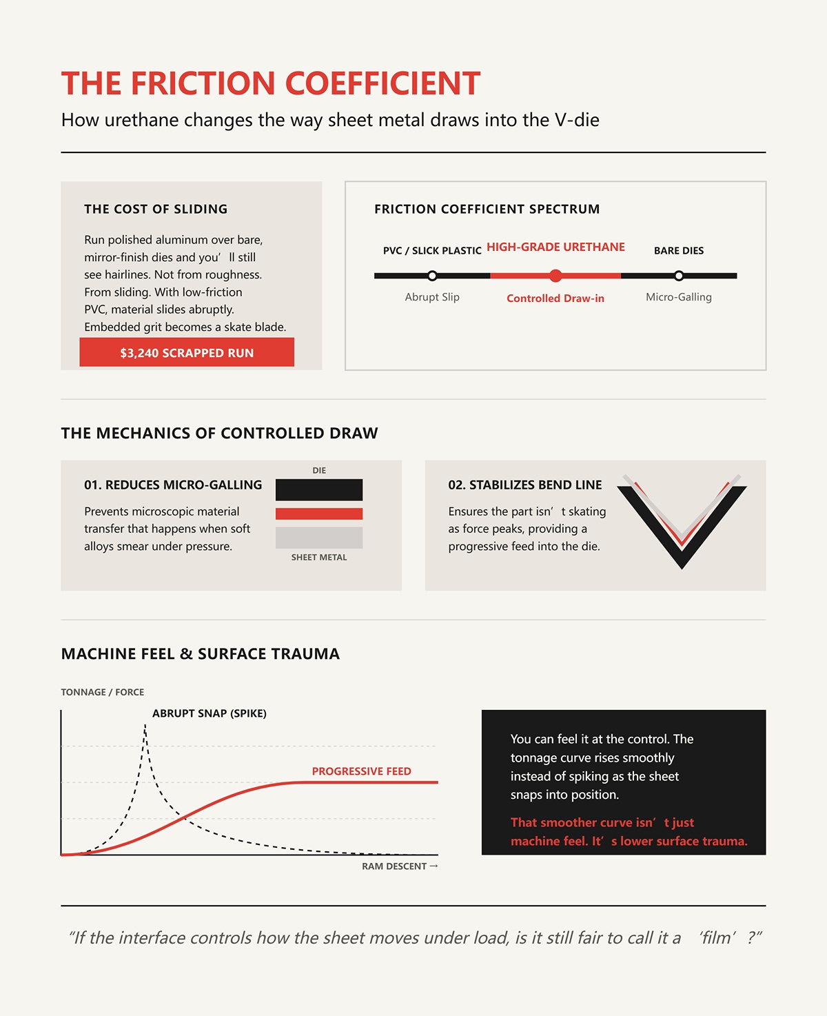
Run polished aluminum over bare, mirror-finish dies and you’ll still see hairlines. Not from roughness. From sliding.
As the ram descends, the sheet has to draw into the V. With low-friction interfaces—like PVC—the material slides abruptly. Any embedded grit becomes a skate blade, dragged the full flange length. I’ve scrapped runs where the only visible defect was a single continuous line, perfectly centered, $3,240 gone because the film let the panel travel too freely.
High-grade urethane changes that interaction because its coefficient of friction is higher than slick plastic but lower than raw steel-on-aluminum contact. It grips just enough to control draw-in. Instead of a sudden slip, you get a more progressive feed into the die.
That controlled draw does two things. First, it reduces micro-galling—the microscopic material transfer that happens when soft alloys smear under pressure. Second, it stabilizes the bend line so the part isn’t skating as force peaks.
You can feel it at the control. The tonnage curve rises smoothly instead of spiking as the sheet snaps into position. That smoother curve isn’t just machine feel. It’s lower surface trauma.
If the interface controls how the sheet moves under load, is it still fair to call it a “film”?
Take a V-die with a 0.500-inch opening. Contact happens along two narrow shoulders. Even if those shoulders are polished, they’re still edges. Edges concentrate stress.
Bare metal to metal, that stress prints whatever lives on the die surface into the part—tooling marks, embedded chips, even the faint grain from a resurfacing pass. I’ve seen pre-coated steel come off with ghost lines that matched the die’s grinding direction exactly. The die wasn’t rough. The pressure was focused.
When urethane compresses, it spreads that load laterally. Not infinitely. Just enough. The contact patch widens from a knife-edge line to a slightly broader, compliant zone. Force divided over a larger area equals lower peak pressure. Lower peak pressure means less imprinting.
Imagine pressing your thumbnail into hardwood versus into a rubber pad on top of hardwood. Same hand. Different mark. The pad doesn’t eliminate force; it distributes it.
That distribution is why multi-purpose urethane dies can form tighter radii across varying materials. The material adapts under load, acting like a temporary custom die for each thickness. For a shop running mixed alloys in the same week, that adaptability isn’t a convenience. It’s insurance.
Insurance that sits directly between the ram and your profit margin.
Which brings us to the practical question a foreman actually cares about: if urethane’s behavior depends on durometer, compression range, and how it’s mounted to the die, how do you compare options in dollars per bend instead of dollars per roll?
Twenty-four panels at $202 each.
That was a single stainless façade run—brushed, pre-finished, laser-cut with decorative slots. We bent them on a standard .030-inch film that “had always worked.” By panel eighteen, the inside legs started showing faint shoulder lines near the slots. Not across the whole flange—only where geometry concentrated force. We kept running. By panel twenty-four, every piece had ghosting around the cutouts. Total scrap: $4,848. The film didn’t tear. It just softened, compressed more than it had at the start of the shift, and changed the pressure pattern under the brake.
So when someone asks how to compare urethane in dollars per bend, I don’t start with price per roll. I start with: how stable is the interface from the first hit to the five-hundredth?
On paper, you’ll see 70A, 80A, 90A, 95A—durometer ratings that describe hardness. In practice, you usually get two thicknesses in the market: .015″ and .030″. That’s it. So the real variable isn’t thickness so much as hardness and how it behaves under your tonnage window.
Run 14-gauge 304 stainless at 60 tons across a narrow V. A 70A strip will wrap beautifully on the first ten bends. By the fiftieth, it’s permanently compressed at the centerline. Polyurethane doesn’t fail like tape. It creeps. As it wears, it effectively becomes softer and more elastic in that contact zone. Your bottom-of-stroke position hasn’t changed. The ram hasn’t moved. But the angle opens up half a degree because the film isn’t resisting the same way it did in the morning.
That’s the drift critics talk about when they say nylon is “more repeatable.” Nylon doesn’t compress as much, so it holds geometry longer. It also imprints more readily and doesn’t control friction the same way. Different failure mode.
Now switch to .063-inch pre-painted aluminum. A 95A film will survive forever. It also won’t conform much at lower tonnage. You’ll get protection, but not that controlled draw-in we talked about earlier. The sheet can skate, especially around holes and notches, and die marks show up exactly where PVC-coated material still fails—at geometric stress risers.
So matching durometer isn’t about “softer for soft metal, harder for hard metal.” It’s about matching elastic compression range to your actual load per inch. If your brake never pushes the film into its working zone, you’re not using a load-bearing interface. You’re laying down an expensive placemat.
Scrap-Saver Rule: Choose a durometer that reaches controlled elastic compression at your real tonnage, not your theoretical maximum.
I’ve pulled adhesive-backed film off a lower die after a long stainless run and felt the tack change with my thumb. Friction heats the contact zone. Not red-hot, but warm enough to soften some pressure-sensitive adhesives.
Does that mean self-sticking film always leaves residue? No. It means residue risk scales with heat and dwell time. Heavy-gauge stainless, tight radii, long production runs—more heat. Short aluminum runs at moderate tonnage—less.
The real cost isn’t the five minutes of solvent cleanup. It’s what happens when residue builds unevenly along the die shoulders. That changes local height by a few thousandths. A few thousandths at the shoulder becomes angle variation across a 10-foot panel. You chase it at the control, bumping depth, and now your “repeatability problem” gets blamed on the ram when it’s actually adhesive buildup.
On the other hand, adhesive-backed film doesn’t migrate. It stays where you put it. No mid-shift repositioning. In high-tonnage work where slip equals scratches, that stability can outweigh cleanup time.
So the question isn’t “adhesive or not?” It’s “does the thermal profile of this job justify mechanical retention instead?”
Scrap-Saver Rule: If your die shoulders run hot enough to soften adhesive, assume they’re hot enough to distort bend consistency and plan your retention method accordingly.
On our 60mm European-style rail system, magnetic holders with height adjustment are a gift. You set front-to-back, dial height to match die stack, and the film tracks with the tool. Change dies, slide the holders, keep moving.
Loose-laid film is faster at first. Throw it down, cycle the ram, let friction pin it. In a single-material, single-die run, it works. In high-mix—swapping from a 1.000-inch V to a 0.500-inch V three times before lunch—it starts to tell on you.
Here’s how it fails: not catastrophically. It creeps. The sheet drags it forward a sixteenth. Then an eighth. Now the film edge sits under only one die shoulder. Pressure distribution is asymmetric. One flange is clean. The other has a faint line that shows up only under certain light. You don’t catch it until parts are off the brake.
Magnetic or rail-mounted systems fail differently. They don’t creep, but they depend on correct setup height. Too low, and the film never fully engages. Too high, and you pre-load it before the sheet even contacts the die, changing bend math.
And that depends on your machine architecture. A head-to-head comparison without factoring in rail standard, die height, and operator discipline is a half-truth.
Scrap-Saver Rule: In high-mix environments, prioritize retention methods that eliminate lateral creep before you chase marginal gains in setup speed.
| Aspect | Magnetic / Rail-Mounted Film Holders | Loose-Laid Film |
|---|---|---|
| Basic Setup | Mounted on 60mm European-style rail system; adjustable front-to-back and height to match die stack | Placed directly on die; held in place by friction during ram cycle |
| Initial Speed | Requires setup and height dialing | Faster at first; simply lay down and cycle |
| Best Use Case | High-mix production with frequent die changes | Single-material, single-die runs |
| Performance in High-Mix | Stable when properly set; slide holders and continue | Begins to shift during frequent V-die swaps |
| Primary Failure Mode | Incorrect height setup (too low: no full engagement; too high: pre-load alters bend math) | Gradual lateral creep under sheet movement |
| Failure Characteristics | Does not creep; errors tied to setup precision | Creeps incrementally (1/16″, then 1/8″); asymmetrical pressure distribution |
| Quality Impact | Bend math variation if misadjusted | Uneven flange quality; faint lines visible under certain light |
| Detection Timing | Typically noticeable during setup or first bends | Often detected after parts leave the brake |
| Dependency Factors | Machine architecture, rail standard, die height, operator discipline | Material friction, die changes, operator attention |
| Scrap-Saver Rule | Prioritize retention methods that eliminate lateral creep in high-mix environments | Marginal setup speed gains do not outweigh creep-related scrap risk |
Let’s run a clean hypothetical.
A $200 roll yields 8,000 bends before wear-induced angle drift exceeds your tolerance window. That’s $0.025 per bend. A cheaper $120 roll lasts 3,000 bends before centerline compression changes your angles enough to require rework or produce visible marking. That’s $0.04 per bend.
The cheaper roll feels responsible at purchase. It’s 40% less upfront. But per bend, it’s 60% more expensive.
Now layer in one rejected architectural panel at $1,200 because film creep or wear printed a die shoulder around a cutout. Your premium roll would have to prevent a single reject in its lifespan to pay for itself six times over.
And we haven’t priced die wear. When film degrades and thins unevenly, you get localized metal-to-metal contact. That’s not theoretical. I’ve seen polished lower dies pick up micro-galling that required resurfacing. One die regrind can run $600 to $900 depending on size.
But here’s the part most ROI spreadsheets miss: performance window. Urethane doesn’t deliver identical protection from first bend to last. As it wears, compression increases, repeatability decreases. Your true cost per bend should only count bends within your acceptable tolerance band. Once you start adjusting depth to chase angle drift, you’re spending labor to compensate for material fatigue.
When did we decide that losing finished parts was cheaper than upgrading the layer that protects every single bend
If the interface between the sheet and the die is elastic, compressible, and wearing in real time, then thickness becomes the next variable you can’t ignore. How much that .015″ or .030″ changes your bend deduction and required tonnage isn’t academic—it’s math that lives at the control.
Last spring we ran 14-gauge pre-painted steel through a 0.750-inch V-die with 0.015-inch urethane on the shoulders. Bend deduction was dialed. Angles were within half a degree across a 10-foot panel. Then purchasing swapped in 0.030-inch film from the same supplier—same durometer, double the thickness. No program changes. First part off the brake was 1.8 degrees open, flange short by 0.042 inches. The ram wasn’t wrong. We had just changed the geometry under 60 tons of force.
Here’s the mechanism: urethane doesn’t just sit there. It compresses. With 0.015-inch film, you might see 30–40% compression at working tonnage. With 0.030-inch, total compression can exceed the original 0.015-inch stack height, effectively lifting the sheet higher in the die during the early phase of the stroke. That shifts the neutral axis and increases the effective inside radius before full die contact. Your CNC still thinks it’s bending steel-to-steel. It isn’t.
If you add 0.030-inch of urethane and don’t adjust your bend deductions, the brake isn’t wrong—you are.
Scrap-Saver Rule: Treat any change in film thickness as a tooling change that requires recalculating bend deduction before the next part hits the backgauge.
On pre-painted 16-gauge, 0.015-inch high-durometer urethane is usually enough to prevent shoulder marking without materially inflating the inside radius. The coating is thin. You’re protecting paint, not compensating for mill scale or surface roughness. At typical air-bend tonnage, that thinner layer compresses predictably and bottoms out closer to steel-to-steel geometry.
Now switch to galvanized.
The zinc layer is softer and slightly irregular. Operators get nervous about flaking at tight radii and reach for 0.030-inch “just to be safe.” But that thicker pad does two things at once: it cushions the coating and increases the effective die opening because the sheet rides on a compressible base before contacting the die shoulders. In a narrow V—say 0.500-inch—0.030-inch per side means you’ve functionally narrowed the opening during initial contact, then widened it as the urethane flows. That’s not a stable condition. It’s a moving target.
I’ve seen galvanized parts crack not because the radius was too tight in steel terms, but because the program drove extra depth to compensate for angle springback induced by over-padding. More depth means more strain at the outer fibers. The coating fails first. Then the base metal follows.
So where’s the line? In practice, 0.015-inch is the default for painted and galvanized under moderate tonnage; 0.030-inch earns its place only when surface tolerance is critical and die width is generous enough to absorb the added compliance without distorting radius. Thickness choice is not about how nervous you feel—it’s about how much geometry drift your die can tolerate.
Scrap-Saver Rule: Start at 0.015-inch for coated steels and move to 0.030-inch only if your die width and bend math can absorb the added compliance without radius instability.
Picture a 0.375-inch V-die bending 0.060-inch aluminum with 0.030-inch urethane laid across both shoulders. That’s not padding anymore. That’s a secondary forming medium.
As the ram descends, the punch forces the sheet into a layer that behaves like a dense rubber gasket. The urethane flows laterally before it fully compresses. That flow supports the sheet closer to the punch tip, effectively increasing the inside radius beyond what the die width alone would dictate. Once the urethane rebounds after unloading, springback compounds because the sheet was never fully seated against rigid steel at peak load.
The result is a radius that measures larger than your air-bend chart predicts and an angle that opens more than your springback table anticipates. You correct by adding depth. Now the urethane is preloaded before the sheet fully engages. Next part, slightly different sheet thickness, slightly different compression. Your inside radius walks around by a few thousandths, and your angle drifts by a degree across a run.
That’s not the brake losing precision. That’s you asking an elastic layer to behave like hardened tool steel.
Scrap-Saver Rule: Never pair thick urethane with a narrow V-die unless you have validated the resulting inside radius and springback across multiple sheets, not just a single first article.
I once logged tonnage on a 10-foot 12-gauge mild steel bend with and without 0.030-inch high-density urethane. Same die. Same punch. Steel-to-steel averaged 48 tons. With urethane, peak load climbed to 58–60 tons before angle closed. That’s not trivial.
But that logic ignores what 60 tons of force does in a 1/8-inch contact zone.
Part of that extra 10–12 tons isn’t going into the steel at all. It’s compressing the urethane to its working thickness. You’re spending machine capacity to deform a protective layer. On a press running near its rated limit, that margin matters. On galvanized or higher-strength material, that additional force can push you from safe forming into coating fracture territory.
There’s also machine behavior to consider. Higher tonnage means more deflection in the ram and bed. Even with crowning, additional load changes how evenly force distributes across the length. You think you added film for protection. You may have just introduced angle variation at the ends.
This is where urethane as a load-bearing component becomes literal. It carries load. It demands load. And the brake responds accordingly.
Scrap-Saver Rule: Measure actual tonnage with and without film on critical jobs and confirm your machine has capacity margin before committing to thicker urethane.
We had a job—twenty-four panels at $202 each—where 0.030-inch film was non-negotiable because the finish was mirror-grade. First article came out long on both legs by 0.055 inches total. Bend deduction in the program assumed a 0.090-inch inside radius from the air-bend chart. Actual measured radius with film was 0.118 inches.
That 0.028-inch radius increase shifts bend allowance. For a 90-degree bend in 0.125-inch aluminum, that change alone can alter bend deduction by roughly 0.040–0.060 inches depending on K-factor. That’s not trimming error. That’s geometry.
The fix wasn’t mystical. We measured the actual inside radius formed with the urethane in place. Recalculated bend allowance using that radius and a verified K-factor from a cut-and-etch sample. Updated the CNC program. Ran three validation parts. Locked it in. The brake did exactly what it was told once we told it the truth.
High-grade urethane isn’t an “add-on.” It’s part of your tooling stack. That means your bend tables, your springback compensation, and your depth settings must reflect its compressed working thickness, not its nominal roll thickness. Otherwise you’re programming for steel and bending into rubber.
And this is where calculation meets discipline—because even the right numbers fall apart if the film isn’t applied flat, centered, and at consistent height on the bed and die.
Scrap-Saver Rule: Always measure the formed inside radius with urethane installed and recalculate bend deduction from that real geometry before releasing production.
You’ve measured the inside radius. You’ve recalculated bend deduction. The brake is programmed for the compressed working thickness of the film.
So why does second shift still call you over when angles drift and scratches show up halfway through a run?
Because geometry isn’t the only variable. Installation is.
If urethane is a load-bearing layer, then how you lay it on the die is no different than how you seat a punch in the ram: sloppy equals movement, and movement under 60 tons becomes damage. I’ve watched shops spend an hour dialing in a first article, then throw a roll of film across the bed like a shop rag and wonder why part eighteen looks different than part two. Mid-run tearing isn’t bad luck. It’s stored energy releasing where the film was misapplied.
This is the insurance policy between the ram and your profit margin. Either it absorbs the hit consistently, or it passes the hit straight into a finished panel.
Scrap-Saver Rule: If the film affects bend geometry, treat its installation with the same repeatability as your punch and die setup—no exceptions.
We’re not detailing a show car. We’re creating friction control.
Rust scale is obvious. You feel it with a fingertip; it prints through thin aluminum like Braille. But oil residue is quieter and more dangerous. A thin film of hydraulic mist on the die shoulders turns urethane into a slip sheet, and when the ram descends, that slip concentrates compression in localized zones instead of distributing it evenly across the V.
That’s where tearing starts.
Under load, the urethane wants to grip steel. If it can’t, it stretches microscopically at the point of highest pressure—usually right at the die radius. Do that a few hundred cycles and you get a split that runs lengthwise. Not dramatic. Just enough to emboss a line into a $202 mirror-grade panel on part twenty-four.
Oil changes friction. Rust changes height. Both change how the load flows through the film.
Wipe the die shoulders with solvent. Scotch the scale off with a fine abrasive. You’re not polishing; you’re normalizing contact so the urethane sees uniform support across its width.
Scrap-Saver Rule: Clean die shoulders to bare, consistent steel before every film install—remove oil to control friction and remove scale to control height.
A wrinkle is just excess material with nowhere to go.
When the ram closes, that excess doesn’t disappear. It gets pressed into the work.
Picture a slight wave across the film, barely visible. Under 60 tons in a 1/8-inch contact zone, that wave becomes a ridge. The punch forces the sheet into it, and the urethane compresses unevenly—thicker at the wrinkle, thinner beside it. That thickness variation changes the effective V-opening locally, which shifts inside radius by a few thousandths. Enough to alter angle by a fraction of a degree. Enough to make you chase depth adjustments that were never the real problem.
And the surface? The wrinkle edge becomes a pressure line. The brake doesn’t know it’s cosmetic. It just sees resistance.
I tension the roll like I’m stretching layout string—firm, not banjo tight. One operator feeds, the other smooths from center outward, palms flat, eliminating air pockets before they become compression pockets. If the film wants to curl back on itself, that’s stored stress from the roll memory. Let it relax off the machine for a few minutes before laying it down.
Wrinkles are future scratches waiting for the ram to press them into a finished part.
Scrap-Saver Rule: Apply urethane under controlled, even tension and smooth from the center outward—any visible ripple is a guaranteed pressure mark under load.
Adhesive-backed films solve movement and create another problem—residue and inconsistent stack height.
I prefer non-adhesive high-grade urethane and a mechanical hold.
Here’s the method: align the film flush with the front edge of the die, clamp both ends lightly with low-profile spring clamps outside the bend zone, then run a single strip of quality masking tape along the back edge only—away from the die shoulders. The tape is not structural; it prevents creep during indexing. The clamps handle tension.
Why not tape across the die face? Because tape compresses differently than urethane. Under load, it squeezes out like toothpaste and leaves a thickness void behind it. Now your load path changes mid-stroke. You just introduced a variable you can’t see.
This clamp-and-tape approach adds maybe ninety seconds to setup. Ninety seconds is cheaper than one rejected panel at $202. I’ve scrapped twenty-four panels at $202 before because a film shifted 1/16 inch and exposed raw die shoulder on the return flange.
Movement is the enemy. Restraint without distortion is the goal.
Scrap-Saver Rule: Secure non-adhesive urethane with end clamps and rear-edge tape only—never place compressible tape in the load path.
Even perfect installation has a lifespan.
Urethane doesn’t fail all at once. It telegraphs. The die shoulders polish a track into it. You’ll see a slightly darker band where aluminum oxide or galvanized particles embed into the surface. That embedded grit becomes a cutting compound.
Ignore it, and the next part pays.
Run your finger across the wear path every ten to twenty cycles on cosmetic work. If you feel a groove or see particulate speckling, advance the roll an inch or two. Don’t wait for a scratch to confirm what your eyes already told you. High-volume European shops complain that urethane loses repeatability as it softens. They’re not wrong—but most of that inconsistency shows up first as uneven wear at the shoulders, not wholesale material collapse.
Advancing the roll is cheaper than polishing out a line that shouldn’t exist.
But here’s the boundary: when you’re running high-tonnage, narrow V-dies at production pace, the film will degrade faster than your shift rhythm likes. There’s a limit where steel tooling—or a different protective medium—makes more sense.
Protection has a breaking point. So does denial.
Scrap-Saver Rule: Inspect shoulder wear bands proactively and advance the urethane before embedded particles or grooves can print into a finished surface.
I remember the first time a crew asked me, straight-faced, to lay film for a coining job on 3/16 aluminum. Eight-foot panels. Cosmetic side out. Full bottoming, chasing a tight inside radius. The brake chart called for tonnage that made the ram grunt.
They were thinking scratch protection.
I was thinking about what happens when you ask a compressible layer to survive forces designed to cold-form metal.
Up to this point, we’ve treated urethane as a disciplined, load-sharing interface—installed flat, tensioned correctly, monitored like tooling. That discipline keeps you profitable in air bending. But coining is a different animal. In air bending, the sheet touches the punch nose and the die shoulders; the material floats between them. In coining, the ram drives the punch tip into the material until it conforms to the die angle. You are no longer guiding metal. You are crushing it into shape.
And anything between steel and steel becomes another thing the ram has to crush.
Even high-grade polyester urethane—the type that resists sliding abrasion and shrugs off shock—has a compressive limit. I won’t invent a magic tonnage number, because it depends on V-opening, material width, and punch radius. But I’ll give you the mechanism: as tonnage climbs, contact pressure at the die shoulders spikes. That pressure exceeds the elastic range of the film. The urethane stops springing back and starts flowing. Microscopic shear turns into surface glazing. Glazing turns into heat. Heat accelerates breakdown. What looked like a reusable barrier becomes a thinning shim.
But that logic ignores what 60 tons of force does in a 1/8-inch contact zone.
Under coining loads, the film isn’t “protecting.” It’s being compacted thinner at the shoulders and thicker in the center. That changes your effective V-opening mid-stroke. You’ll see it as angle drift you can’t quite dial out. You’ll chase depth adjustments. Meanwhile, the film is dying one compression cycle at a time.
Scrap-Saver Rule: If the job requires true coining or bottoming at charted full tonnage, assume urethane film will plastically deform and remove it from the load path.
Take a controlled comparison. Same 0.125 aluminum, same 1-inch V-die. First run: air bend to 90 degrees. Second run: coin to lock in angle and reduce springback.
In the air bend, the urethane sees localized contact at the shoulders and light sliding under the sheet. A quality 90-durometer film can survive dozens—sometimes hundreds—of cycles if you advance it before grit embeds. The stress is intermittent and partially elastic. The film recovers.
In the coining pass, recovery disappears. The punch tip drives the sheet fully into the die angle, compressing the film across a broader area. Now you’re not asking the urethane to cushion. You’re asking it to resist being flattened between two hardened tools. The compressive set accumulates. After a handful of strokes, measure the film thickness at the shoulder track. It won’t be what you started with.
And once thickness changes, geometry changes.
Polyether urethanes handle impingement abrasion better than polyester types; polyester handles sliding better. That chemistry matters in air bending, where friction mode dominates. In coining, chemistry is secondary to physics. When contact pressure crosses the elastic threshold, both families yield. Add shop-floor heat from repetitive cycling and you lower that threshold further. What survives ten hits at room temperature may glaze in five during a production run.
So the real answer to “at what tonnage?” is this: the moment your process requires plastic deformation of the sheet through full die contact, you are operating at a pressure level where film life drops from “managed consumable” to “unpredictable failure point.”
That’s not a moral judgment. It’s a load case.
Now picture a 30-degree punch nose, sharp enough that you can feel the edge through a glove. We’re forming an acute return flange on anodized aluminum. Cosmetic side out, of course.
Lay 0.030-inch film over the die and cycle the ram slowly. Watch what happens at the punch tip. The contact area narrows dramatically compared to a 90-degree tool. Pressure concentrates along a thinner line. The urethane has nowhere to distribute load laterally before the punch penetrates the sheet and forces it into the V.
With a sharp punch, the failure mode isn’t global compression. It’s cutting and shear. The film may not explode. It may self-seal minor nicks—that’s one advantage of precision-cast urethane sheets. But at 30 degrees, each stroke scores the same line. Repetition turns that score into a split. The split becomes a ridge. The ridge prints into the part.
Can film work for a few prototype hits? Yes, if tonnage is moderate and you’re watching wear every cycle. Is it viable for a 200-piece cosmetic run? Not without babysitting it like a critical dimension.
And when protection requires constant vigilance to prevent the protector from becoming the defect, you have to ask what you’re really saving.
I scrapped twenty-four panels at $202 once because we insisted on “making the roll work” on a high-tonnage architectural job. The film didn’t tear dramatically. It compressed unevenly. Angle drift crept in. A faint shoulder line appeared on part nineteen. By part twenty-four, we had a stack of polished aluminum worth $4,848 and a crew pretending it was bad luck.
It wasn’t bad luck. It was overreliance.
Permanent urethane die inserts—cast pads seated into the die cavity—change the equation. They’re thicker. They’re supported across their full width. They’re designed to be load-bearing, not just sacrificial. Because they’re captive, they don’t creep. Because they’re dimensionally controlled—often within a few thousandths—they introduce a stable, predictable compressible layer.
You still account for thickness in your bend calculations. You still monitor wear. But you’re no longer laying a temporary insurance policy between the ram and your profit margin and hoping it survives coining loads.
Here’s the practical transition point I use: if the job demands full-tonnage bottoming, acute tooling below 45 degrees for production quantities, or cycle counts where advancing film every 10–20 hits disrupts flow, I price in dedicated inserts. Not as a luxury. As tooling.
When did we decide that losing finished parts was cheaper than upgrading the layer that protects every single bend
Scrap-Saver Rule: The moment urethane film requires more management than your punch and die, replace it with a permanent, load-rated insert and treat surface protection as tooling—not packaging.
If film fails under high-tonnage and acute tooling, the answer isn’t “thicker film.” It’s specifying urethane the way you specify punches and dies: by load case, chemistry, support method, and service life.
A permanent insert is not a roll laid across a V. It is a cast or machined urethane pad, usually polyether-based for hydrolysis resistance, seated fully inside the die cavity so the load path runs through supported material instead of a floating strip. You choose durometer based on forming mode—softer for cosmetic air bends where you want conformity, harder when angle stability under higher tonnage matters. Then you lock in thickness tolerance, because a ±0.005 variation in a captive insert shows up as angle drift just as surely as a worn die shoulder.
This is where most shops stumble. They buy “urethane” the way they buy shop rags. But polyether versus polyester chemistry determines how that insert survives humidity, heat from the brake, and coolant mist hanging in the air. Polyester can handle sliding abrasion well, but it’s more vulnerable to hydrolysis in warm, damp shops. Polyether resists moisture attack and holds properties longer in real conditions—not brochure conditions. If your brake sits in a non‑climate‑controlled bay in August, chemistry is not academic.
Scrap-Saver Rule: Specify insert chemistry and durometer to the load case and environment before you ever price the job.
Quality control is the next fault line. Urethane that isn’t mixed, degassed, and cured correctly can carry unreacted components, dimensional inconsistency, or internal bubbles that collapse under pressure. I’ve seen inserts that looked perfect on the bench and telegraphed void lines into anodized panels by part twelve. A reputable supplier will provide dimensional tolerances, cure protocol, and batch traceability; if they can’t speak that language, they’re selling material, not tooling.
And remember the health side. Properly cured inserts are generally stable in service, but freshly cast or poorly manufactured polyurethane can off-gas VOCs, especially when heated. The brake generates heat. Friction generates heat. If you’re dropping a new insert into a production cell, let it post-cure and ventilate according to manufacturer guidance before you park an operator over it for eight hours. Production strategy includes air quality.
So implementation becomes procedural, not casual. Seat the insert so it is fully supported across the die width. Eliminate gaps that allow lateral creep. Recalculate bend deductions and springback with the insert’s compressibility accounted for—run test coupons, measure actual angle under production tonnage, and lock those numbers into the program. Then define an inspection interval based on cycle count and visual shoulder wear, the same way you track punch tip radius growth.
You’re not protecting parts anymore. You’re engineering the interface between the ram and your profit margin.
Which changes what you measure.
The first time you stop polishing die shoulders mid-run feels like cheating.
With film, especially under higher load, grit embeds. The film shifts. A faint line appears on part seven. Now the brake is idle while someone hits the die with Scotch-Brite, wipes it down, re-lays film, and bumps the program because thickness changed. Ten minutes here. Fifteen there. It doesn’t show up as scrap. It shows up as “normal.”
A seated insert doesn’t migrate, and it doesn’t trap debris the same way a loose layer does. Because it’s captive, sliding occurs against a stable surface, not a shifting membrane. That stability means fewer surprise stoppages to chase cosmetic ghosts. Over a 300-part run, even four avoided clean-and-reset cycles at 12 minutes each is nearly an hour of regained spindle time—hypothetical, yes, but every foreman knows how quickly those “small” interruptions stack.
The brake makes money when the ram is moving under control, not when a lead hand is polishing hardened steel to undo what a $40 roll caused.
Scrap-Saver Rule: If surface protection forces you to stop the ram to maintain tooling, the protection is costing more than it saves.
Scrap is loud. Rework is quiet.
Twenty-four panels at $202 is $4,848 you can circle in red ink. But what about the two hours a fabricator spends feathering out a faint shoulder mark on brushed stainless, hoping the grain hides it? What about the parts that pass inspection but take extra handling because operators don’t trust the surface?
When inserts hold geometry consistently, angle drift shrinks. When angle drift shrinks, downstream fit-up improves. Fewer clamps. Fewer persuasion taps with a dead blow. The savings compound across departments that never touch the brake.
This is the non-obvious part: protection dictates geometry stability, and geometry stability dictates labor hours far beyond bending. True cost per bend includes the welder who doesn’t have to fight a misaligned flange and the finisher who doesn’t have to explain a polished streak to a project manager.
“But that logic ignores what 60 tons of force does in a 1/8-inch contact zone.” Exactly. That force either deforms a controlled, rated insert predictably—or it finds the weakest link and writes its signature across your part.
Scrap-Saver Rule: Track rework hours tied to bend inconsistency and assign them back to your surface protection choice.
Cosmetic aluminum and prefinished stainless shouldn’t feel like gambling.
With loose film, you’re watching for wrinkles, splits, and embedded grit every cycle. Protection depends on vigilance. One missed advance of the roll and the ridge prints into a $202 mirror-grade panel because the layer meant to protect it became the defect.
A permanent insert shifts finish quality from operator awareness to system design. The contact surface is uniform, tension-free, and repeatable. Once you validate that combination—insert hardness, thickness, bend program, tonnage—you can run sensitive material without babysitting every stroke. Flawless becomes the baseline, not the best-case scenario.
That doesn’t mean infinite life. Inserts wear. They compress over time. UV exposure can yellow certain formulations if you store them poorly. Service life must be defined in cycles or visual criteria, not wishful thinking. But defined wear is manageable. Random film failure is not.
When did we decide that losing finished parts was cheaper than upgrading the layer that protects every single bend
The shops that treat urethane as a line item chase scratches forever. The ones that treat it as load-rated tooling start budgeting in cycles, tolerances, and chemistry—and their scrap reports get boring.
Scrap-Saver Rule: Make surface protection a specified, inspected, and budgeted tooling asset—or keep paying for it as unpredictable scrap.