

It’s 11:47 p.m., and the job that should’ve wrapped up an hour ago just produced its fourth under-bent part. Same program. Same tooling. New sheet stock. The display insists the Y-axis is perfectly on target, yet your 90° bend keeps checking in at 88°, sometimes 87.8°. You’ve recalibrated the back gauge twice, tweaked material compensation, even increased dwell time—but that final 2° still refuses to close. Somewhere deep in the machine, a mechanical component is feeding false truth to the controller, and every adjustment you make just reinforces the deception.
Here’s the real problem: what looks like a programming fault almost never is. When a press brake drifts a few degrees, nine times out of ten the issue lies in the physics, not the code. This is what operators call the “midnight crunch” moment—production pressuring you to deliver, quality control flagging rejects, and the controller tempting you to adjust one more offset. The real fix doesn’t come from cranking up the overbend number but from a quick, methodical 7–10 minute diagnostic check that identifies the real source before you even touch the keypad.
When bend angles consistently miss by the same amount, most operators blame control software. In truth, the controller is only showing what its sensors tell it—and that input data can drift. Position feedback from encoders, assumptions about material thickness, and hydraulics affected by temperature all contribute to deviation, even while the display stays deceptively precise. This is the “ghost in the machine,” revealing itself as a steady one-to-three-degree miss every cycle.
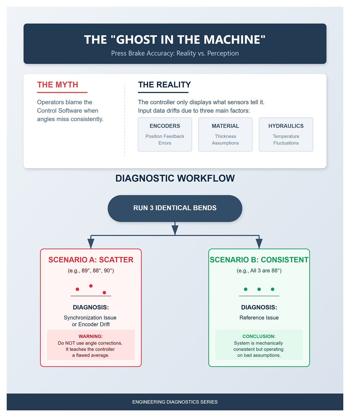
Start by determining whether the issue lies in repeatability or in reference. Run three identical bends from the same program. If all three finish equally under-bent, the system is mechanically consistent but operating on bad assumptions. However, if results scatter—say one part measures 89°, the next 88°, and another 90°—you’re likely dealing with synchronization or encoder drift. Chasing that inconsistency with angle corrections only teaches the controller a flawed average, guaranteeing the next batch will fail in a different way.
When bend angles start coming out wrong, the back gauge usually takes the blame—mainly because it’s the most visible component and seems easy to recalibrate. But tweaking it in response to a bad angle is like adjusting your ruler to fix a crooked cut—it doesn’t solve the real problem. The back gauge determines flange length, not the bend angle. Unless the gauge is physically loose or overshoots its stop, recalibrating it won’t affect the ram’s closing depth, which is what actually controls the angle.
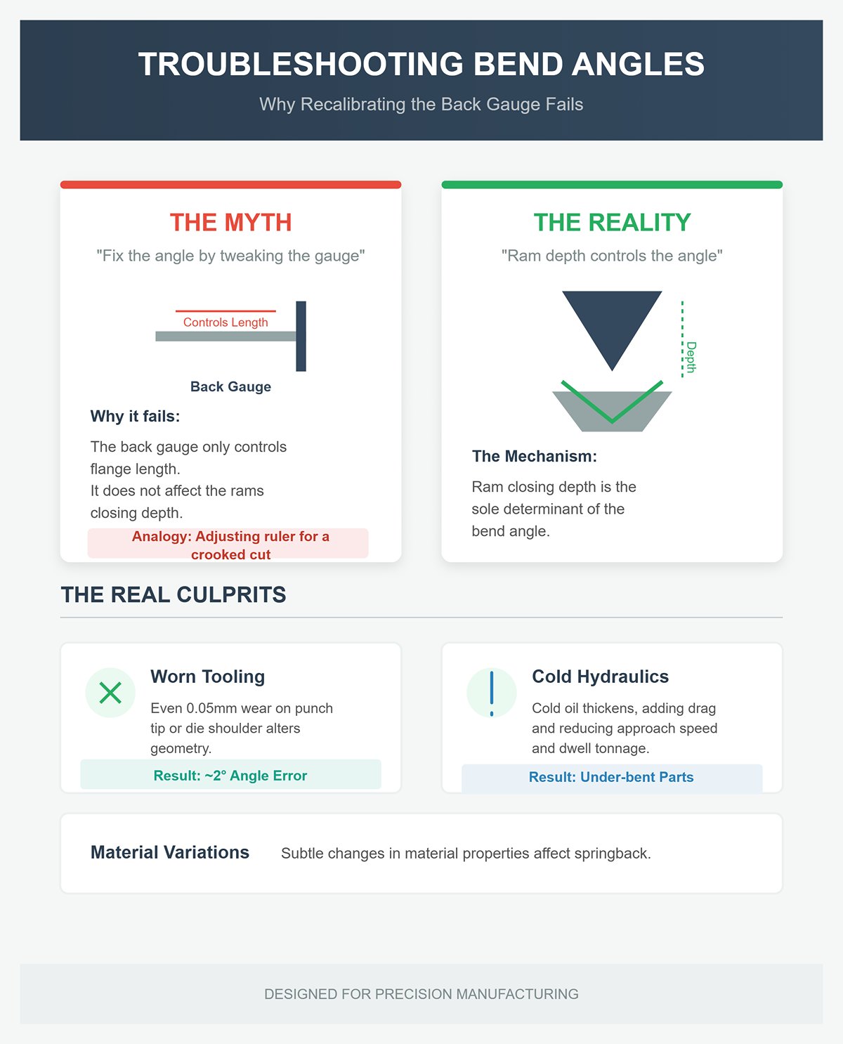
In the classic case of getting 88° when you wanted 90°, recalibrating the back gauge is just wasted effort while the real culprits—worn tooling, cold hydraulics, or subtle material variations—keep doing their damage. Wear as slight as 0.05 mm on a punch tip or die shoulder alters contact geometry and springback enough to throw your angle off by about 2°. Similarly, cold hydraulic oil at the start of a shift thickens and adds drag, reducing approach speed and limiting full‑tonnage dwell. The result: under‑bent parts until the oil warms up. No keypad adjustment can compensate for fluid viscosity.
Experienced operators know the rule: when the press brake misbehaves, check the machine itself before blaming its programming. A quick, systematic triage helps you pinpoint the four usual suspects—tooling wear, hydraulic synchronization, material inconsistency, and back‑gauge or encoder drift—that cause most sub‑degree errors.
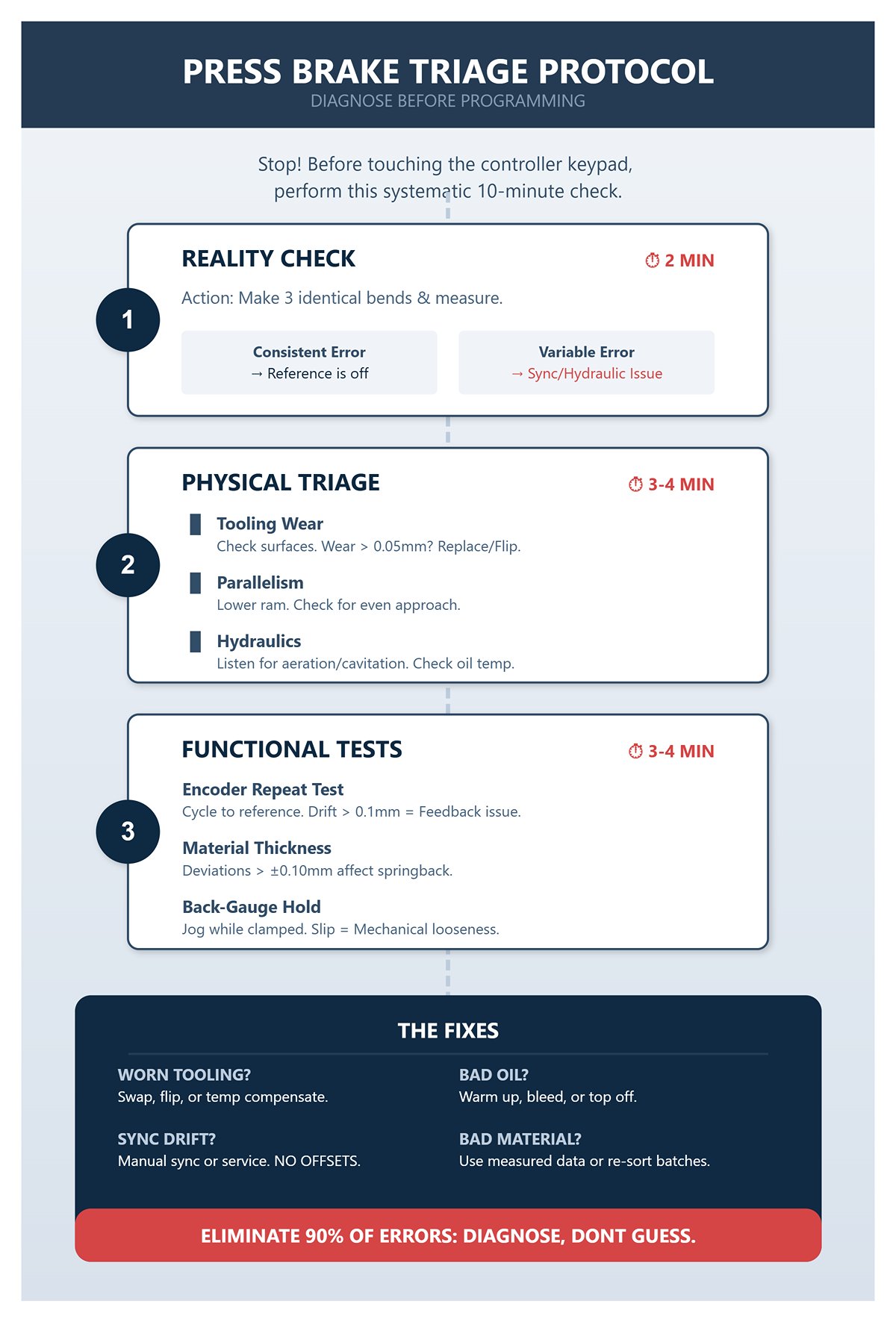
1. Reality Check (2 min) – Make three identical bends and measure each with a gauge or digital protractor. If the error is consistent, the system is repeatable but its reference is off. If the error varies, suspect a hydraulic or feedback synchronization issue.
2. Physical Triage (3–4 min)
3. Quick Functional Tests (3–4 min)
Once these checks are complete, the next step is refreshingly simple:
Operators who follow this process reliably eliminate about 90% of those late‑night angle‑chasing sessions. The reason is straightforward: they diagnose instead of guessing. Controller tweaks and back‑gauge recalibrations only disguise the underlying mechanical shift. When you treat the press brake like the precision hydraulic machine it truly is—a system defined by movement, feedback, and steel‑to‑steel geometry—you replace guesswork with control. That stubborn 88° bend becomes what it should be: a quick, two‑minute fix, not an all‑night ordeal.
When a bend feels soft, the instinct is to start punching in corrections on the controller—don’t. Every digital adjustment compounds the problem if the press brake’s physical state has already shifted. Consistency in forming begins with mechanical accuracy: everything flat, aligned, seated, and clean. A brief physical check—using your hands, eyes, and a simple shim—often reveals more than any diagnostics screen ever could.
Begin with a rapid health check—a ninety‑second investment that can save you hours of troubleshooting. Inspect for oil leaks beneath the ram or around manifolds; hydraulic seepage leads to uneven pressure response. Listen to the pump’s tone—if it whines or cavitates, there’s air trapped or fluid running low. Cycle the ram through one dry stroke; any hesitation points to valve contamination or scoring. Jog the back gauge—if it doesn’t glide smoothly, you’re likely dealing with rail debris or dried lubricant, both sources of inaccurate referencing. If anything seems off, step away from the keypad. Mechanical faults only amplify digital errors.
The first deceiver in any shop isn’t the operator—it’s the material stack itself. Controllers assume every springback calculation is based on a single “nominal” thickness, but real-world batches vary. A ±0.1 mm fluctuation across sheets can alter springback enough to turn a perfect 90° bend into 88° or 92°. The program hasn’t changed—the metal has.
Quick check: grab a digital caliper and test five sheets—three points per sheet: at the edge, center, and near the tooling reference. If the variance exceeds 0.1 mm, consider the batch mixed. No caliper available? Try a density test instead: weigh a piece of known area and compare its grams‑per‑square‑centimeter to the spec. Any mismatch reveals an alloy or temper deviation.
Immediate remedy: separate the stack into “thin” and “thick” groups. Run the thinnest first; the longer ram stroke will make springback more consistent. When pressed for time, apply a controlled overbend—about +5 % for soft aluminum or +2–3° for mild steel—then confirm with three quick paper‑gauge readings. Always label the batch clearly; the controller’s calculations are only as accurate as the material data you feed it.
Skipping this check is how late‑shift parts end up under‑bent: even a 0.1 mm thicker sheet on a narrow V die spikes tonnage and distorts the bend radius. Once you align your program with the actual material, every adjustment regains its meaning.
A single sheet of standard paper—about 0.1 mm thick—can reveal whether the issue lies in geometry or hydraulics. Slip it between the punch and workpiece along the bend line, make one trial bend, then open. If the angle tightens or steadies within half a degree, the real problem is alignment or seating, not the program itself.
Perform the test at three points—center, left third, and right third. Differences between these areas indicate a tilt or uneven ram synchronization. Uniform improvement across all spots points to a worn punch tip or contamination in the die seat. In minutes, you’ll know whether the fault is system‑wide or localized.
Next, with the punch retracted, check the tip by touch. A flattened area wider than 0.05 mm alters the effective bend radius. Ensure clamp screws or wedges haven’t loosened; even a single speck of debris can lift the tool enough to distort angles. Clean thoroughly, tighten securely, reseat, and remove any oil film or grit.
If re‑clamping fails to fix the issue, rotate the punch or swap in a backup die set to complete the job. Repeat the paper‑shim test—if the angle no longer changes under direct contact, you’ve verified the geometry problem is solved. Ten minutes of testing now can save hours of chasing phantom software errors later.
Every die develops its own “comfort zone”—a small section the operator instinctively favors. With every bend, that area becomes polished into a mirror‑bright groove. It may look harmless, but once bend angles start to wander, the problem reveals itself. The groove shifts the line of contact, alters the neutral axis, and causes unpredictable changes in springback.
A quick diagnostic takes only seconds: run a fingernail along the punch edge—if it snags, the tip radius has flattened. Then inspect the lower V‑die under strong light; a shiny strip longer than a few millimeters signals concentrated pressure and uneven wear. Any depression deeper than 0.2 mm disrupts material flow and makes bends spring open before they should.
To keep production moving, act fast: if spare tooling is available, swap out the punch or die. Practice changeovers until they’re routine five‑minute jobs. If no spare exists, shift the part slightly sideways so the bend line engages an unworn section, and mark that new reference to ensure consistency across operator shifts.
For a lasting fix, re‑grind or retire the tooling as soon as you detect a flat wider than 0.05 mm or when the polished area reaches half the die’s width. Record tool life at every job closeout—this builds a predictive wear curve and prevents mid‑order surprises.
Most press‑brake manuals jump straight to software corrections and compensation tables, bypassing the basic physics check. But no amount of controller magic can make up for a dirty seating surface, inconsistent material thickness, or a grooved die. This initial “physical triage” lays the only reliable foundation the software can interpret accurately: stable geometry and predictable material behavior. Once that’s confirmed, then—and only then—the keypad earns your attention. Skip it, and every program tweak just becomes a chase after phantom errors in steel.
Many operators reach for the most obvious fix—individually adjusting the Y1 and Y2 axes until both sides of the bend appear correct. It may work temporarily, but the consistency soon vanishes. The issue is straightforward: adjusting Y1 and Y2 independently doesn’t correct the underlying cause—it simply disguises it. A press brake depends on both cylinders moving in perfect sync. When you start offsetting one side against the other, the control system loses its baseline reference. The part might look acceptable today, but torque imbalance, crowning distortion, and thermal drift will compound that offset tomorrow.
The right method is to rely on controller‑managed program offsets. Both Cybelec and Delem systems feature adaptive correction routines that fine‑tune stroke or depth based on measured deviations in bend angle rather than arbitrary position shifts. Because these adjustments are computed by the controller to move both cylinders in harmony toward the commanded angle, they preserve symmetry and ensure full synchronization.
Picture “global correction” as trying to tune a guitar by bending one string until it sounds roughly right—it might work momentarily, but everything falls out of tune when you change keys. True calibration means the entire machine—hydraulic balance, ram flex, crowning, and feedback sensors—must reference one unified zero point. Programming offsets need to be systemic rather than local. Once the mechanical and hydraulic foundations are verified, use the controller’s built‑in correction tools: they deliver predictable compensation, maintain synchronization stability, and automatically log each change in the job memory for traceability.
Cybelec controllers—including the ModEva, VisiTouch, CybTouch, and the latest Cybelec 7 series—offer two methods for refining bend accuracy: Angle Correction and Depth Mode. Understanding the difference is key to avoiding the classic programming mistake of applying both simultaneously without a precise measurement reference.
Angle Correction relies on feedback. You perform a test bend, measure the resulting angle, and enter that value into the controller. The CNC then recalculates the necessary stroke depth to produce the programmed target angle on the next cycle. Because this adjustment stays within the program’s logic, synchronization and crowning compensation remain intact. Use Angle Correction when minor variations occur—such as shifts in material batch, thickness, or oil temperature affecting springback—while the mechanical alignment stays consistent.
Depth Mode operates purely on positional control: both cylinders travel to a defined coordinate (for example, –75.35 mm from machine zero). This method ensures flawless left‑right synchronization and repeatable die penetration, assuming the material’s elastic properties are already characterized. Depth Mode is ideal for precision bottoming or coining applications where maintaining perfect parallel ram motion overrides the need to achieve a specific air‑bent angle.
A quick and reliable routine combines both methods: first, confirm synchronization is within ±0.01 mm (most machines display live deviation values). Then, bend a test piece in Angle Correction mode, record the achieved angle, and rerun the same piece in Depth Mode using the adjusted stroke. This establishes the connection between ram stroke and resulting angle—essentially your “material modulus map” for that setup. Avoid continuously adding new angle‑correction points if left and right readings start to diverge; that signals a hydraulic or mechanical fault, not a control discrepancy.
Delem controllers—from the DA‑52 to the DA‑69T—determine the bottom dead center (BDC) by combining known tool geometry with programmed bend parameters. Operators sometimes override this BDC to fine‑tune the angle, but an unchecked override may push the ram past its safe travel range, risking damage to sensors or tooling.
The correct procedure is to use the Offset or Fine‑Tune parameter fields. Each allows small, controlled adjustments relative to the calculated BDC—typically in increments of 0.05 to 0.10 mm. Enter a positive offset to reduce bending (for a shallower angle) or a negative one to increase bending (for a tighter angle). Always perform a dry run without material to confirm adequate tool clearance. Never deactivate synchronization or bypass stroke‑limit interlocks for angle corrections—these safeguards prevent ram and die overtravel.
If cumulative corrections exceed roughly 0.3 mm, stop and reassess the base data—tool dimensions or material thickness are probably incorrect. When available, Delem’s adaptive bending function can automatically learn the real BDC after a calibration bend, reducing the need for manual offsets. Record every offset within the job recipe to ensure consistency for repeat orders.
Experienced press‑brake operators treat BDC overrides like precision instruments: small, intentional, and verified each time. Large adjustments hide setup errors and compromise future program consistency. Used correctly, careful offsetting protects tooling, preserves machine accuracy, and maintains the repeatability that Delem’s system is designed to deliver.
Each unsynchronized adjustment adds mechanical stress to the system. When Y1 travels deeper than Y2 to straighten a misaligned part, it twists the frame and invalidates crowning settings, leading long bends to taper in subsequent runs. Over time, even the ram’s reference line shifts, forcing increasingly large software compensations and compromising the consistency of produced parts.
The proper approach is a structured correction sequence: begin with mechanical realignment, proceed with global offset adjustments, and finish with adaptive fine‑tuning. Check oil temperature and pressure balance, reset both Y axes, confirm the crowning baseline, and then allow the controller algorithm to statistically correct small residual angle errors over several cycles. A practical guideline: if a correction exceeds 1.5° or 0.2 mm, it signals a mechanical problem that requires inspection.
Effective press‑brake programming recognizes that precision arises from stable, repeatable links among data points—tool geometry, crowning profile, material elasticity—and real‑time sensor feedback. Systems like Cybelec and Delem incorporate advanced functions to maintain these relationships. The skilled operator’s discipline lies in using them correctly: applying systemic corrections within the control logic instead of making spontaneous, unrecorded adjustments that disrupt synchronization. Master this principle, and “angle drift” becomes a problem solved once, not an ongoing chase.
Every experienced press‑brake operator eventually faces the “canoe effect”—a subtle yet damaging distortion that appears when bending long parts. Under high load, the ram and bed deflect elastically: the ends stay relatively rigid while the center sags. For bends exceeding one meter, this uneven stress distribution increases end force by roughly 20–30%, making the center “open up” by two to three degrees. A nominal 90° bend may measure 92° at mid‑span and 88° near the edges—an inconsistency invisible during setup but unmistakable once assembled.
The most reliable way to confirm bed deflection is with a straightforward three‑point test. Form a sample bend and measure the angle at both ends as well as at the center. If the center differs by more than one degree from either end, you’ve verified the presence of canoe distortion. Checking the workpiece immediately after bending with a straightedge exposes the mechanics behind it: a sag exceeding 0.1 mm across the bed length indicates under‑compensation. That tiny deflection compounds under load, multiplying with each ton pressed and producing angular drift that no digital controller can fully correct. Reading the bow isn’t about intuition—it’s a form of early diagnosis. Knowing the depth and position of deflection tells you whether the automatic crowning system can handle it or whether manual intervention is needed.
Modern hydraulic crowning systems are designed specifically to neutralize press brake bowing by pre‑arching the bed in the opposite direction of expected deflection. When properly calibrated, they can improve angular accuracy by 80–90%, cutting variation from ±3° down to a tight ±0.25°. The controller interprets pressure data and material properties, directing precision wedge cylinders that lift the bed’s center just before the ram reaches forming pressure. The outcome is consistent contact along the length—and consistent bend angles throughout.
On Cybelec controls, navigate to Machine > Compensation > Angle Correction to adjust. Enter the measured difference between center and ends, and the system automatically recalibrates the crowning ratio. For machines showing structural wear, manual mode allows a fine‑tuned +0.5° center boost through slider adjustments—a quick, effective way to recover accuracy without physical repairs. Delem systems manage this under Setup > Crowning, integrating live angle‑gauge feedback to continually optimize hydraulic pressure. Their adaptive algorithm maintains a steady ±0.25° accuracy even after ten consecutive cycles, whereas manually set crowning typically drifts by about ±1°.
Not every press brake gains from electronic crowning. Traditional mechanical models rely on wedge blocks or hydraulic jacks beneath the bed to form the same compensating curve. Accuracy is critical—lift the bed center between 0.002 and 0.005 in. Testing is hands‑on: slide paper shims under a straightedge until no light shows through at mid‑span. When the raised center perfectly offsets the natural sag, bend angles level out. From a design standpoint, upward‑acting brakes—common on Amada machines—rarely suffer from the canoe effect because their symmetrical load path flexes the frame upward rather than downward, reducing or eliminating the need for crowning adjustments.
Crowning systems assume a sound, even bed surface. Once wear or sag exceeds 0.2 mm, electronic and mechanical compensation both lose precision, leaving operators to chase angle errors by trial and correction. When maintenance downtime simply isn’t possible—during overnight runs or urgent production—a controlled shim technique can temporarily restore bending consistency.
The practical fix costs about the same as a modest lunch. Use thin 0.010‑inch steel shims, placing them under the die at one‑quarter points from each end while leaving the center bare. This geometric offset counteracts the measured bed depression, effectively reconstructing a correct camber beneath the tooling. Run one test piece to confirm results—if the center tightens by roughly 1–2°, alignment is achieved. Expect reliable performance for fifty to a hundred cycles, enough to complete most rush orders before scheduled service.
Two small habits distinguish seasoned professionals from quick‑fix experimenters. First, install shims before activating any auto‑crowning sequence—the control sensors assume a perfectly flat bed, and introducing a false baseline will cause excessive correction. Second, record shim thicknesses and positions for the next shift. Unlogged flattening adjustments cause nearly seventy percent of “ghost compensation” angle discrepancies investigated in production audits.
Shims aren’t a replacement for precision surface grinding, but they reinforce a key concept: effective adaptive control begins with a mechanically sound base. Electronic calibration can only refine accuracy when the physical geometry behaves predictably. In high‑mix fabrication environments, mastering the synergy between hardware and software keeps first‑article approvals above 95% and reduces rework caused by inconsistent bend angles by as much as 25%.
The canoe effect turns predictive programming into hands‑on bending mastery. Operators who learn to interpret deflection, properly calibrate crowning, and apply practical interim fixes move from reacting to angle errors to preventing them altogether. From here, calibration verification and adaptive routines shift from theory to habit—laying the foundation for continuous, repeatable precision.
Every flawless bend begins with perfectly parallel motion. When the Y1 and Y2 cylinders drift even a tenth of a millimeter apart, the ram stops acting like a uniform beam and turns into a lever. The part tells the story—center angles open 1–2°, while the ends overbend. Operators often try to correct springback or crowning, but in roughly 70 % of cases, the true culprit is hydraulic synchronization lag, not programming.
Modern controls reveal the issue before the part exposes it. During a dry run, open the Y‑axis feedback screen and watch Y1/Y2 deviation as the ram transitions through the speed‑change zone. If the deviation rises beyond 0.1 mm, synchronization has slipped out of automatic correction—the servo valves are competing rather than sharing the load. If both sides hold within 0.05 mm at bottom‑dead‑center, the root cause lies in mechanical alignment, not hydraulics.
To make diagnostic certainty second nature, post this quick two‑minute test right on the console:
Bleed the system through the valve screws for about two minutes at mid‑stroke, ensuring the oil temperature is below 45 °C, then rerun the check. When the Y‑axis readout moves with steady, rhythmic balance—as even as a heartbeat—you’ve restored the symmetry every bend relies on.
A reliable rule of thumb: the machine whispers before it screams. If the ram hesitates, tilts, or groans, it’s calling for you to correct sync before the cylinders engrave that twist into every part produced during the shift.
When Y‑axis drift distorts the ends, tonnage drift destroys the tooling. The display gives the first honest signal: calculated load at 100 tons, peak reading at 150. That isn’t more power—it’s metal past its yield point and dies taking the abuse. A tonnage spike exceeding 85 % of the relief setpoint means the hydraulic circuit is compensating for a mechanical obstruction that shouldn’t exist.
A sharp crunch, a double vibration at the bottom of the stroke, or a sudden 20–30 % spike above nominal load—all are the machine’s way of translating distress into data. The damage builds quickly: over-bottoming twists the ram, throws the cylinders out of sync, and flexes the bed until angles drift two degrees from side to side. The next shift ends up chasing phantom springback that was never springback to begin with.
Think of the tonnage chart as a stoplight you can read in real time while the press runs:
Nothing shouts louder than a spike in tonnage—it’s the hydraulic system’s way of pleading for balance.
Every operator has faced that midnight decision—does this issue justify a service call? The answer fits on one gloved hand: if three or more of the five checks stay green within ten minutes, finish the run. If not, call the tech before the costs escalate.
| Check | 1‑Minute Test | Go / Continue Production | No‑Go / Call Tech |
|---|---|---|---|
| 1. Y Sync | Run three dry cycles; compare end vs. center angle | Deviation < 0.1 mm; smooth motion | Tilt > 0.2 mm; audible lag |
| 2. Tonnage | Perform one test bend on scrap | ≤ 85 % of relief; no crunch | Spike > 90 %; safety trip |
| 3. Oil / Pressure | Check gauge stability and pump noise | Normal PSI; quiet pump | Low reading; cavitation present |
| 4. Valves | Observe movement in both directions | Even speed, no hesitation | Sticking or leakage; clean and retest |
| 5. Return Speed | Time full upstroke | < 3 s | > 5 s under load |
Follow this binary system like scripture and you’ll avoid 80 % of those “urgent” service calls that drain maintenance budgets. The hidden advantage: your press learns your rhythm. Consistent, routine checks keep servo valves responsive—intermittent operation just confuses them.
If a cylinder imbalance won’t correct or the relief valve refuses to reseat, that’s your turning point—beyond this, you risk warping the bed or damaging tooling, turning a five‑minute diagnosis into a $5,000 failure masked as an overtime save.
The pivotal realization is this: true hydraulic understanding lies in data, not intuition. The press brake communicates in numbers—minute Y1/Y2 variations, tonnage ratios, return‑time seconds—and those fluent in that numerical language manage consistency through mastery rather than luck.
Your first move tomorrow morning? Affix the “Go/No‑Go” checklist directly beside the start button. Treat it as a definitive guide for every setup, regardless of how routine the task appears.
Now picture this: the ram lowering in perfect alignment, the tonnage line steady and green—no crunches, no tilt—only seamless, balanced pressure translating code into creation. That’s the moment when the machine and the operator act as one.
Everything you’ve done so far—crowning, shimming, calibration—has led to this precise moment of truth: will the hydraulics remain faithful, or are you about to chase phantom errors through steel?
Once you can answer that question with certainty, you’ve moved beyond simply running the press brake—you’re truly commanding it.


