

I’ve watched a new hire lean on the pedal like he was stomping grapes. One-eighth inch mild steel in the V-die, ram coming down hard. The sheet hit ninety degrees under load. Ram lifted. The part relaxed to ninety-four.
He looked at the machine like it lied to him.
That four degrees is where the illusion starts.
To a beginner, the ram comes down, the metal bends, end of story. Hydraulic pressure in, angle out. Like crushing a soda can.
But metal isn’t a sponge. It’s a lattice of crystals that stretch before they surrender. When you first push that sheet into the die, the steel is still elastic—meaning it’s behaving like a spring. You can unload it and it will return to flat. Nothing permanent has happened yet.
The bend only becomes real at a very specific threshold.

Picture the ram descending on that same 1/8 inch sheet. At first, resistance climbs smoothly. You’re just flexing it. Then, at a certain stress—the yield point—the internal structure starts to slip. Dislocations move. The metal stops “remembering” flat.
That’s plastic deformation. Permanent change.
Before yield, you’re just stretching a spring. After yield, you’re reshaping it.
Here’s the part most beginners miss: the machine doesn’t announce that moment. There’s no click, no light. You’re dialing in tonnage based on material thickness, die opening, and tensile strength so that you just cross that line—without overshooting wildly.
The Tonnage Trap is thinking more pressure equals better bends. Past yield, extra force mostly deflects the machine and tools instead of improving the angle.
Scar tissue: I’ve seen operators chase angle errors with pressure and end up bowing the ram a few thousandths—then wonder why their long parts come out wavy.
If yielding makes the bend permanent, why didn’t that ninety-degree bend stay at ninety?
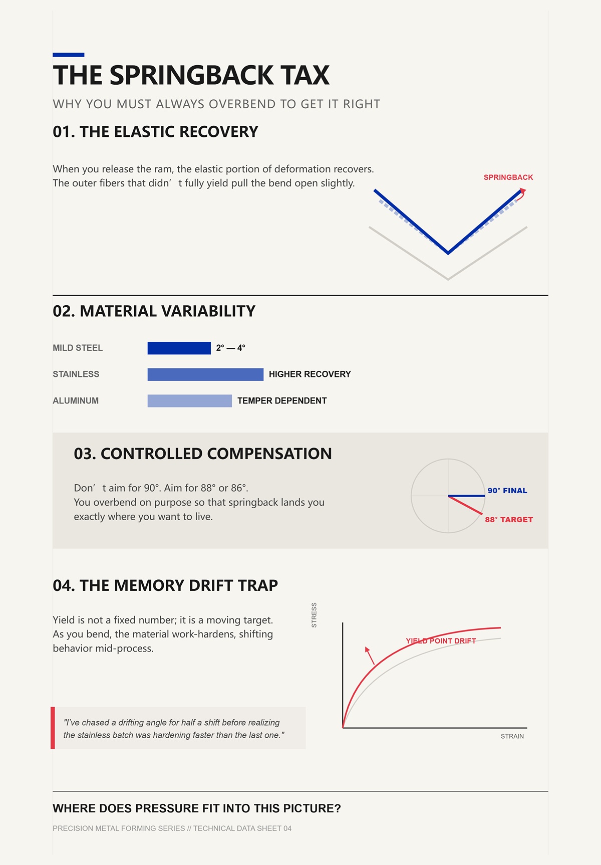
When you release the ram, the elastic portion of that deformation recovers. The outer fibers that didn’t fully yield pull the bend open slightly. That’s springback.
On mild steel, maybe two to four degrees in air bending. On stainless, more. On aluminum, it depends on temper.
So you don’t aim for ninety. You aim for eighty-eight, maybe eighty-six, depending on the job. You overbend on purpose so that springback lands you where you want to live.
That’s not guesswork. It’s controlled compensation.
And here’s where things get interesting: as you bend, the material work-hardens. Its yield point creeps upward. The metal you’re finishing with isn’t quite the metal you started with. If you run too fast or dwell too long, you shift the behavior mid-process.
The Memory Drift Trap is assuming yield is a fixed number instead of a moving target during forming.
Scar tissue: I’ve chased a drifting angle for half a shift before realizing the stainless batch was hardening faster than the last one.
If angle depends on how deep you push past yield and how much springback you predict, where does pressure actually fit into this picture?
Take two setups. Same sheet. Same machine.
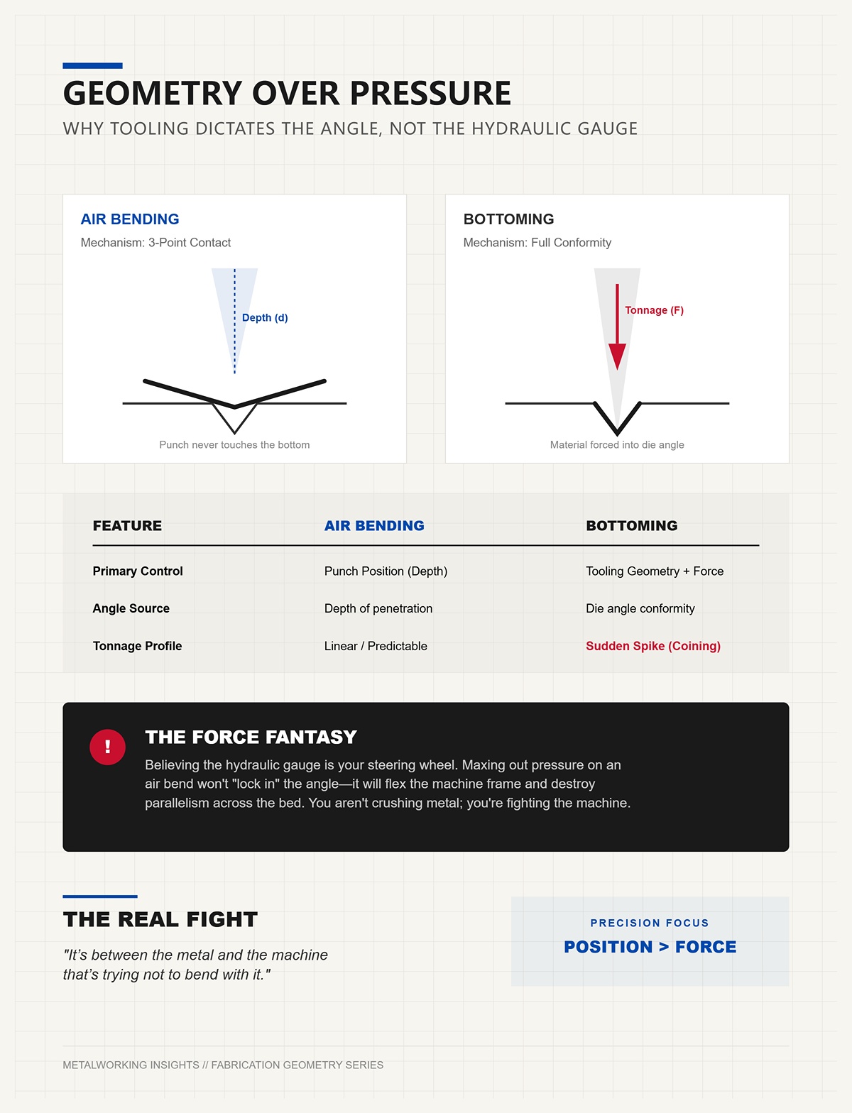
In air bending, the punch never forces the metal to the bottom of the V-die. The sheet touches the punch tip and the die shoulders, forming a three-point bend. The final angle depends on how deep the punch penetrates into the die opening. Change the depth by a few thousandths, you change the angle.
Pressure just gets you to the required depth. Geometry sets the result.
In bottoming, you drive the sheet firmly into the die angle itself. Now the tooling angle dominates, and tonnage spikes because you’re coining the material—forcing it to conform.
See the shift?
Air bending is about position control. Bottoming leans harder on force. But even there, you’re still managing yield and springback, not crushing metal into obedience.
The Force Fantasy is believing the hydraulic gauge is your steering wheel. In reality, punch depth and tool geometry are.
Scar tissue: I’ve watched operators max out pressure on an air bend thinking they’d “lock in” the angle, only to flex the frame and lose parallelism across the bed.
If angle comes from geometry and controlled overbend—not raw tonnage—then the real fight isn’t inside the metal alone.
It’s between the metal and the machine that’s trying not to bend with it.
| Aspect | Air Bending | Bottoming |
|---|---|---|
| Setup | Same sheet and same machine as comparison baseline | Same sheet and same machine as comparison baseline |
| Contact Method | Punch contacts sheet at three points (punch tip and die shoulders) | Sheet is driven firmly into the die angle |
| How Angle Is Determined | Determined by punch penetration depth into the die opening | Determined primarily by tooling (die) angle |
| Role of Pressure | Pressure only achieves required depth; geometry sets the angle | Tonnage increases significantly to force material into die shape (coining effect) |
| Control Principle | Position control (precise depth management) | Greater reliance on force, while still managing yield and springback |
| Sensitivity | Small depth changes (thousandths) significantly affect angle | Angle dominated by die geometry once fully bottomed |
| Common Misconception | Increasing pressure will “lock in” the angle | Force alone guarantees precision |
| Risk Observed | Excess pressure can flex machine frame and affect bed parallelism | High tonnage increases machine stress |
| Core Insight | Angle comes from geometry and controlled overbend—not raw tonnage | Even with higher force, geometry and material behavior remain decisive |
| Underlying Tension | Balance between metal deformation and machine rigidity | Balance between material yield and machine structural limits |
On my old 10-foot brake, I could bend a 3-foot bracket dead-on and miss the same angle by a degree at 9 feet without touching the program. Same material. Same die. Same target depth.
If geometry sets angle, and depth sets geometry, how does machine deflection sneak in and steal accuracy?
Because depth is not what the screen says. It’s where the punch actually lands under load — after the frame stretches, the ram bows, and the drive system finishes delivering force. Two machines can both wear a “100-ton” badge. But the one that can’t control how that force arrives, ramps, and stops will never hold the same punch depth across the bed. And if depth drifts a few thousandths, angle drifts with it.
So when we ask “How hard?” we’re really asking: How does this machine create force, and how well can it stop exactly where geometry demands?
Different drive systems answer that question in five very different ways.
I learned on a flywheel machine that sounded like a freight train. Big spinning mass up top, clutch engages, crankshaft converts rotation into vertical ram motion. Once that clutch bites, the ram is coming down. Period.
Here’s the mechanism. A mechanical press stores energy in a spinning flywheel. When you engage the clutch, that stored kinetic energy dumps through a crank linkage. Force peaks near bottom dead center — that last bit of stroke. Before that, tonnage is climbing but not yet at maximum.
That shape of the force curve matters.
In air bending, we care about position. But a mechanical press is governed by geometry of the crank, not a finely metered hydraulic flow. You can’t feather the last thousandth easily. The ram wants to pass through bottom dead center because the linkage is still moving. So you’re timing clutch engagement, brake release, and hoping inertia doesn’t carry you deeper than planned.
That’s why they’re fast. Stroke rates can be high because you’re not waiting on oil to move. But that same inertia is the Precision Drift Trap. Once energy is in the system, you don’t bleed it off delicately — you arrest it.
Scar tissue: I’ve seen a long part come out crowned because the center of the ram hit peak tonnage a hair earlier in the stroke than the ends, and there was no micro-adjust to correct it mid-hit.
Mechanical presses reward repetition on short runs with fixed setups. But when sheet thickness varies by a few thousandths, or when you’re chasing half-degree tolerances across eight feet, the question becomes uncomfortable:
How do you “shim” depth when the machine’s motion is locked to a spinning wheel?
First time I bent half-inch plate on a modern hydraulic brake, I watched the pressure gauge climb smoothly as the ram descended. No drama. Just controlled push.
Hydraulics generate force by pressurizing oil in cylinders. Pressure times piston area equals force. Simple math. The beauty is control: proportional valves meter flow, servo valves fine-tune it, and you can slow the ram to a crawl in the last few millimeters. That means you can dial in depth with real authority.
And under sustained load, hydraulics shine. Continuous high tonnage on thick plate is their home turf because pressure can be maintained steadily without relying on stored kinetic energy. The frame still deflects, yes — but the system can dwell, hold, and compensate.
Here’s the quiet struggle.
Oil compresses slightly. Hoses expand. Seals flex. Under heavy load, especially across long beds, the two cylinders must stay synchronized. If Y1 and Y2 (left and right cylinders) drift even a few thousandths, the ram tilts. Now your punch depth isn’t parallel.
Electro-hydraulic CNC systems close that loop with linear scales measuring each side independently. Older torsion-bar systems tie both sides mechanically; if one side lags under load, the bar twists and hopes to average it out.
That’s the Parallelism Illusion: assuming equal pressure means equal position. Pressure is force. Position is geometry. They are not the same.
Scar tissue: I’ve chased a taper in a 10-foot stainless panel only to find one cylinder was leading by three thousandths under peak load — invisible on the pressure gauge, obvious in the angle.
Hydraulics remain dominant because they can both generate and modulate serious force. But their precision depends on how well the machine measures and corrects deflection in real time.
So if oil gives us muscle with controllable motion, what happens when we throw oil out entirely?
I visited a shop running a small 22-ton servo-electric brake — ball screws driven by servo motors, no hydraulic unit humming in the background. They were bending thin stainless enclosures under three feet long. Claimed repeatability in the micron range.
Mechanically, it’s clean. A servo motor turns a ball screw — a threaded shaft with recirculating ball bearings that convert rotary motion into linear travel with very high efficiency. Position is tracked by encoders directly on the motor or screw. When the controller says stop, the motor stops. No oil compressing. No valve lag.
For short parts and light gauges, that direct-drive position control is surgical. You can program approach speed, bending speed, and return independently. Energy use drops because the motor only draws power when moving.
But here’s where the marketing posters get thin.
Ball screws have load limits. Under heavy tonnage, they stretch microscopically. The frame still deflects. And dynamic response under thick material can lag compared to hydraulics designed for sustained high pressure. Some comparisons have shown electric systems losing ground in thick, high-tonnage work where pressure stability under load matters more than idle efficiency.
The Efficiency Halo Trap is thinking quieter and cleaner automatically means more accurate in every scenario. Accuracy under load depends on stiffness and feedback, not just motor type.
Scar tissue: I’ve seen a shop buy an electric brake for energy savings, then farm out their thicker jobs because the machine simply wasn’t built to hold depth under that kind of stress.
Servo-electric systems are brilliant scalpels. Hydraulics are controlled hammers. Which tool you pick changes how you fight deflection — and how much of it you can realistically neutralize.
So where does compressed air fit in this orchestra?
I’ve only trusted pneumatic brakes for thin aluminum panels and light brackets. They’re quick. They’re quiet. And they run out of breath fast.
Compressed air drives cylinders much like hydraulics, but air is highly compressible. That means under load, the system behaves like a spring. As resistance increases, the air compresses more before transmitting full force to the ram.
For light-duty work, that springiness isn’t fatal. In fact, cycle times can be quick because the system is simple and fast-moving. For thin sheet where required tonnage is low, pneumatics can outperform heavier hydraulic systems on sheer speed.
Now put quarter-inch steel under it.
Required tonnage climbs sharply with thickness and V-die width. Air compresses further. Control gets spongy. Depth becomes harder to arrest precisely because the medium itself is elastic.
But metal isn’t a sponge. Air is.
That mismatch is the Compliance Cascade: elastic drive system feeding elastic material while the frame flexes in between. You’re stacking springs and hoping for precision.
Scar tissue: I watched a pneumatic unit stall halfway through a thicker bend, pressure maxed, ram shy of target depth — the machine simply couldn’t deliver the force geometry demanded.
Pneumatics have their lane. Step outside it, and deflection wins before you even reach yield.
So even if we choose the “right” muscle, there’s still a brain behind it — or sometimes, not much of one.
I once ran a torsion-bar NC brake where you programmed a single Y-depth. Both cylinders followed together, mechanically linked. If the frame bowed under a long, heavy bend, you compensated by tweaking depth and maybe adding crowning manually.
You were controlling movement.
Modern CNC electro-hydraulic systems measure Y1 and Y2 independently with linear scales mounted near the ram. The controller compares commanded position to actual position thousands of times per second, nudging valves to keep both sides synchronized under load.
That’s programming a result.
The difference shows up on long parts. With NC torsion systems, if one side lags due to uneven load or frame twist, the torsion bar averages the error. With full CNC, each side is corrected in real time. Angular programming can mask small discrepancies on NC, but it’s a workaround — not true parallel control.
The Halfway House Trap is believing servo-driven backgauges and digital screens automatically mean full-axis synchronization. Without independent Y1/Y2 feedback, you’re still trusting the frame more than you should.
Scar tissue: I’ve seen shops chase angle consistency by adjusting backgauge positions when the real culprit was unsynchronized ram travel under load.
Two machines can both claim 100 tons. One delivers it with a spinning flywheel, one with pressurized oil, one with ball screws, one with compressed air. One measures both sides of the ram and corrects mid-bend; another assumes symmetry and hopes.
If angle comes from geometry and controlled overbend — not raw tonnage — then the drive system isn’t just about “how hard.”
It’s about how precisely you can stop, hold, and keep that force perfectly parallel when the music gets loud.
And even with the best drive in the world, the frame itself is still trying to bend.
Picture a 10-foot strip of 1/4-inch A36 laid across the bed. You’ve got the tonnage chart dialed in. The cylinders are synchronized. The controller says both sides are dead level within a few microns. You hit the pedal, and the sheet hit ninety degrees under load.
Then you check it.
Ninety in the center. Eighty-eight and change at both ends.
Nothing “lost pressure.” Nothing slipped. What moved was the machine itself. Under full load, the ram and the bed deflected—bowed microscopically—so the punch penetrated deeper in the middle than at the ends. The drive system did exactly what it was told. The structure translated that force unevenly across its length. If angle comes from geometry and controlled overbend—not raw tonnage—then the real fight isn’t inside the metal alone.
It’s across ten feet of steel trying to behave like a tuning fork under tension.
Doubling material thickness doesn’t just double tonnage; in air bending it roughly quadruples it because required force scales with the square of thickness. Run 1/8-inch mild steel and you’re comfortable. Jump to 1/4-inch in the same V-die and your load climbs fast. That higher load pushes harder against the throat of the frame and the center of the bed, where the span is longest. Deflection increases nonlinearly, but your advertised “200 tons” hasn’t changed. The rating is a ceiling. Parallelism is a moving target.
Scar tissue: I’ve watched a shop blame material variation for a 2-degree taper that was nothing more than mid-span deflection they never measured.
So even if your force is precise and your depth is accurate, how do you keep that ram truly level when the load itself shifts along the bed?
Run a short bracket on the left side only. Now the load is eccentric—off-center. The left cylinder sees higher resistance; the right side is mostly coasting. On an older torsion-bar machine, the mechanical linkage forces both sides to move together, averaging the error. The heavy side wants to lag; the light side wants to run ahead. The bar splits the difference.
You get parallel movement. You don’t get equal force.
Modern CNC brakes read Y1 and Y2 independently with linear scales mounted near the ram. The controller compares commanded and actual position thousands of times per second and nudges each valve separately. If the left side dips under higher load, the system feeds it more pressure to keep positions matched.
Sounds like victory.
But here’s the catch: when thickness jumps or die width shrinks, tonnage spikes sharply. Drop below roughly six times material thickness for your V-opening and required force climbs fast, along with surface marking and unpredictable stress distribution. Now the correction system is fighting harder, amplifying pressure on one side to chase parallelism. You’ve created a tug-of-war between synchronization and structural stiffness.
The Synchronization Trap is believing that equal position always means equal angle. If the frame twists slightly under asymmetric load, the ram can be numerically parallel while the bed itself isn’t presenting a uniform reaction surface.
Scar tissue: I’ve seen operators chase Y1/Y2 offsets for an hour when the real culprit was a narrow die silently overloading one side of the frame.
So even if we keep the ram level side-to-side, why does a perfectly straight bed still produce a curved bend on long parts?
Take that same 10-foot bend, centered this time. Both cylinders balanced. No eccentric load. Before you touch the pedal, the bed is straight within machining tolerance.
Under load, it won’t stay that way.
The punch drives down in the center of the span, and the bed deflects downward there while the side frames resist. The ram, spanning the same width, bows upward slightly at its ends. Together, they create a gap pattern: deepest penetration mid-span, shallower at the tips. The result is a tighter angle in the middle, more open at the ends.
Ironically, the straighter your bed is at rest, the more predictable the bow under load becomes—and the more you must intentionally counteract it.
That’s where crowning comes in. Mechanical or hydraulic crowning systems introduce a controlled upward arc in the bed before the load hits. You’re pre-bending the machine against the expected deflection curve. Dial it right, and when full tonnage arrives, the bed flattens under pressure, distributing force evenly along the length.
You are shimming the instrument before the music starts.
Get it wrong—too little crown—and the center still closes tight. Too much, and the ends overbend. Because tonnage scales with thickness squared, a material change from 3 mm to 6 mm doesn’t just require more force; it demands a different compensation curve. Crowning isn’t a one-time setup. It’s a live adjustment tied to geometry, die width, and material yield.
Scar tissue: I’ve watched a crew run perfect angles all morning, switch to thicker stock after lunch, and spend the afternoon blaming the operator when the only thing that changed was the deflection curve.
Which brings us to the uncomfortable truth: for decades, operators compensated by feel and test bends. Now machines promise to think for you.
Modern systems measure ram position with linear encoders and, in some cases, estimate load through pressure sensors. The controller references a material library—thickness, tensile strength, die opening—and calculates expected deflection. It then adjusts crowning and ram depth automatically during the stroke.
You’re not just commanding depth. You’re programming a predicted elastic event.
On downstroke electro-hydraulic designs, synchronization happens continuously as the ram approaches bottom dead center. The machine can slow, correct Y1/Y2 deviation, and apply dynamic crowning based on real-time feedback. Done right, angle variation across a long bend shrinks dramatically compared to manual machines.
But sensors don’t stiffen steel.
If the frame lacks rigidity, electronic correction increases localized pressure to maintain position, which can deepen structural strain elsewhere. The JEELIX-style downstroke systems improve parallelism, yes—but they also demand accurate tonnage monitoring because compensation itself redistributes force. You’re solving one vector of error while loading another.
The Automation Halo Trap is assuming software cancels physics. It only models it—and only as well as your input data matches reality.
Scar tissue: I’ve seen angle sensors mask a creeping frame fatigue issue for months, until one day the compensation ran out of stroke and the taper came back with teeth.
So we’ve neutralized ram drift, pre-bent the bed against its own sag, and let electronics trim the last few microns. What’s left is the daily craft: choosing tooling ratios that don’t spike tonnage, setting backgauges that don’t twist parts under asymmetric load, and controlling stroke so overbend matches real springback—not catalog values.
That’s where deflection theory either survives contact with the shop floor or gets crushed under its own assumptions.
Picture a 10-foot strip of 1/8-inch mild steel on the bed. You’ve crowned the machine for the load. Material library is dialed in. The screen says 92 tons.
You step on the pedal.
The sheet hit ninety degrees under load.
And when the ram comes up, it relaxes to ninety-four.
That four degrees isn’t a mistake. It’s springback — elastic recovery after the load leaves. But metal isn’t a sponge. It doesn’t rebound randomly. It releases stored elastic strain based on thickness, die width, and yield strength. If angle comes from geometry and controlled overbend—not raw tonnage—then the real fight isn’t inside the metal alone, it’s in how you sequence the setup so the machine, tooling, and material all land on the same number at the same time.
Here’s how you actually do that.
Start with the die, not the tonnage chart.
Take that same 1/8-inch mild steel — 0.125 inch thick. A common rule of thumb is a V-opening about 8 times thickness. That’s a 1-inch die. Plug it into the standard air-bend formula and you’re somewhere around 14–15 tons per foot. Stretch that to 10 feet and you’re flirting with 150 tons.
Now halve the die opening to 0.5 inch. Same material. Same length. The required force nearly doubles because tonnage is inversely proportional to die width. You didn’t change the part. You changed the geometry. And the frame now deflects more under the same job.
The Geometry Trap is thinking tighter dies mean tighter accuracy. What they really mean is higher load and more deflection to neutralize.
Scar tissue: I’ve watched operators chase a two-degree taper that was born the moment they swapped to a narrow die “for precision.”
The die controls inside radius — roughly 16 percent of the V-opening in air bending. That radius determines how much the outer fibers stretch and how much elastic strain you store. Smaller radius, more stored energy, more springback to compensate. You don’t “force” a 90. You overbend to 86 or 88 under load so it relaxes back to 90 after release.
That overbend is geometry-driven. Not ego-driven.
Coining seems like a shortcut. Bottom the punch hard into the die, exceed yield across the thickness, and springback nearly vanishes because you’ve plastically crushed the material to match tooling. But coining spikes tonnage three to five times over air bending. The machine frame, the ram, the pins — everything sees that surge. Vibration creeps in. Emergency overloads trip.
You traded elastic uncertainty for structural strain.
So the first shim in this three-way argument is tooling geometry. Pick a die wide enough to keep tonnage — and therefore deflection — in a controllable range. Choose a punch radius that matches the target inside radius without over-stretching the outer fibers. Map the metal flow before you ever touch the pedal.
Then you ask: if geometry defines the bend line, how do you make sure every part actually lands on that same line?
I once watched a new hire run a batch of brackets. Angles were dead consistent. Lengths were not. Some flanges were off by 0.020 inch. He kept tweaking depth, convinced the ram was wandering.
It wasn’t.
The backgauge fingers were slightly out of parallel — a few thousandths across the span. When the sheet seated against them, it twisted microscopically before the punch even touched it. The machine bent exactly where it was told. The part just wasn’t sitting square.
Backgauges are linear positioning systems — typically ballscrews or belts driven by servos, resolving down to a few microns. They don’t just set flange length. They define where the neutral axis of the bend begins relative to the tooling centerline. If one finger is ahead of the other by 0.003 inch on a 10-foot part, you’ve built a diagonal into the setup.
The machine will faithfully bend that diagonal.
The Alignment Trap is assuming digital readout equals physical truth. Encoders report screw position, not whether the fingers are coplanar under load.
Scar tissue: I’ve seen a perfect Y1/Y2 sync blamed for tapered parts when the real villain was a backgauge rail packed with chips.
On long parts, you support the sheet so gravity doesn’t sag it off the fingers. On asymmetric parts, you reposition gauges to avoid pushing the material sideways as the ram descends. Every contact point is a lever arm that can twist the blank before forming starts.
Parallelism isn’t only about the ram and bed. It’s about how the workpiece enters the fight.
So the geometry is mapped, the blank is seated square. Now comes the moment that separates mechanical brakes from controlled systems: how the stroke decides when enough is enough.
On a modern electro-hydraulic brake, linear encoders sit on each side frame measuring actual ram position, not just cylinder travel. Pressure transducers read hydraulic load. The controller compares target depth to real-time feedback thousands of times during the downstroke.
It isn’t guessing. It’s correcting.
As the punch contacts the sheet, load rises sharply. The frame begins to stretch — yes, stretch — by a few thousandths. That stretch means the ram can be at programmed depth relative to the cylinders but not yet relative to the bed. The controller keeps feeding pressure until encoder feedback says the commanded position under load has been reached.
That’s why a bend might require 0.010 inch deeper penetration under full tonnage than the no-load approach suggested.
Scar tissue: I’ve measured machines that were 0.006 inch taller at rest than under a 120-ton hit. Steel moves. Always.
Mechanical press brakes don’t “feel” this. A crankshaft drives the ram to a fixed bottom dead center. If deflection changes with material or length, the only correction is manual adjustment after the fact. Hydraulic and servo-electric systems trim depth dynamically, but they still live inside the stiffness of the frame. If the required force doubles because you doubled bend length, deflection doubles with it. The controller compensates within its stroke limits — it doesn’t make the C-frame thicker.
The Overconfidence Trap is believing that because most bends come out right, the drama is gone. Modern feedback systems have made the balancing act routine, not irrelevant. Eighty percent of production parts succeed because the operator fed the machine honest geometry, realistic material data, and a die choice that kept tonnage inside the machine’s elastic comfort zone.
When all three agree — tool geometry, material behavior, and ram position — the angle lands within a few thousandths across the span.
You didn’t crush it into submission.
You tuned a long, heavy steel instrument under tension until the note rang true.
Which raises a different question: if running a press brake is really about tuning and feedback, why do we still talk about them as if they’re just big force numbers on a spec sheet?
Walk through any equipment showroom and the first number they’ll shove under your nose is tonnage. Two hundred tons. Three hundred. Bigger must be better.
That’s because tonnage is easy to print on a sticker and easy to compare across brands. Control bandwidth, encoder resolution, Y1/Y2 synchronization accuracy under asymmetric load — those don’t fit on a sales placard. Force is visible. Parallelism under load is not.
If angle comes from geometry and controlled overbend—not raw tonnage—then the real fight isn’t inside the metal alone. It’s inside a long, flexible frame that stretches, twists, and recovers every time you step on the pedal. The sheet hit ninety degrees under load, and the machine was part of that load path. The brake is a controlled elastic structure, not a concrete wall.
But metal isn’t a sponge.
You can’t just soak it with more pressure and expect accuracy to drip out. Past a certain point, extra tonnage doesn’t sharpen control; it magnifies deflection. The beginner’s mistake — The Crusher Trap — is thinking excess capacity equals excess precision. In reality, oversizing without control is like putting a bigger engine in a truck with sloppy steering. You’ll move more force, but you won’t track straighter.
So if tonnage isn’t the north star, what is?
Start treating tonnage as a ceiling, not a goal.
You calculate required force from material thickness, die width, and bend length. That’s basic shop math. Thickness doubles, force goes up roughly four times. Fine. But once you’re comfortably below the machine’s maximum rating, the question shifts from “Can it push hard enough?” to “Can it stop precisely enough under load?”
That’s stroke control.
On paper, two machines might both offer a 10-inch stroke and 200 tons. One uses basic hydraulic synchronization through a torsion bar — a mechanical link tying both cylinders together until bottom dead center. The other runs independent cylinders with linear scales on each side, correcting Y1 and Y2 position in real time.
Under no load, they look identical.
Under a 10-foot asymmetric bend, they are not.
When the left side sees more material than the right, force distribution changes. A torsion bar resists twist mechanically but cannot fine-tune side-to-side penetration once load builds. Independent cylinders can trim each side — if the control loop is fast and calibrated. That “if” is everything. The Independent Cylinder Trap is assuming flexibility automatically means accuracy; without tight feedback, you’ve just created two ways to be wrong.
Scar tissue: I’ve watched a poorly tuned dual-axis system bend a subtle corkscrew into stainless that a simpler, stiffer linkage would have avoided.
So when you read a spec sheet, ask three things: How does it measure ram position under load? How does it synchronize left to right? And how does it compensate for bed deflection across the span? If those answers are vague, the tonnage number is a distraction.
Which leads to the drive systems themselves.
Mechanical brakes run on a crankshaft. The ram goes to a fixed bottom dead center every cycle. Repeatable, yes. Adaptive, no. If material thickness varies or bend length changes, you adjust manually. There’s no listening — only hitting the same note every time whether the instrument is in tune or not.
Hydraulic systems brought modulation. Pressure builds progressively. With proportional valves and encoders, the control can “feel” resistance climbing and stop at programmed depth under load. Upper beam speeds often crawl in the single-digit millimeters per second near contact for a reason: control lives in that narrow window where force and position are both changing. Faster isn’t better if you outrun your feedback loop.
Servo-electric machines replace oil with ball screws and motors. Cleaner. Often faster between bends. Extremely precise in position control because the motor’s rotation directly translates to ram travel. But torque limits replace hydraulic pressure limits; once you approach capacity, the same elastic truths apply. Frames still stretch. Beds still bow. Physics clocks in whether you pay hydraulics or servos.
The Drive-Type Trap is thinking the power source determines accuracy. It doesn’t. The quality of measurement, synchronization, and compensation does.
Scar tissue: I’ve seen a beautifully machined servo brake struggle on long, off-center parts because its crowning system was an afterthought.
So the beginner’s framework becomes simple: choose enough tonnage to stay out of overload, then judge the machine on how intelligently it measures and corrects itself while bending.
What does that buy you on the floor?
Confidence doesn’t come from knowing your machine can hit 300 tons. It comes from knowing why today’s 1/8-inch batch bent differently than yesterday’s.
When you see the brake as a force-control system, you stop reacting emotionally to variation. Angle opened two degrees? You ask: did material yield shift, did die width change effective tonnage, did temperature alter hydraulic response, did Y1/Y2 drift a thousandth? You’re diagnosing a system, not blaming a number.
You also stop being impressed by brute capacity alone. A smaller machine with high-resolution linear scales, responsive valves or drives, and a well-designed crowning system can hold parallelism tighter across real jobs than a larger, dumber frame. That’s non-obvious because force feels powerful, and control feels invisible.
The industry sells tonnage because it’s simple to compare. Buyers choose it because it feels safe. But safety in bending isn’t about how hard you can push. It’s about how precisely you can stop — and how evenly you can distribute that stop across ten feet of steel that’s fighting back.
Once you see that, the spec sheet changes in your hands. The big number fades. Your eyes go hunting for feedback loops, synchronization strategy, and compensation design.
And the next time someone brags about crushing power, you’ll ask a quieter, sharper question: how does it stay parallel when the music gets loud?


