

I’ve watched a press brake operator bury a punch an extra 0.040 in., convinced the angle would finally snap to 60°. Instead it opened up to 62°.
He stared at the screen like it lied to him. It didn’t. His intuition did.
That’s the air-bending trap — believing depth equals angle, and angle lives in the controller. That logic works right up until geometry stops being free.
In standard V-die air bending, the sheet only touches at three points: punch tip and die shoulders. Everything else is air. That freedom is why you can chase ±1° by bumping depth a few thousandths. The material can slide, stretch, and redistribute stress as you steer it.
Now picture a complex profile — a molded tang form with sidewalls, offsets, tight internal radii. The sheet isn’t hanging in space anymore. It’s contacting surfaces early and often. Material flow isn’t free; it’s guided, sometimes trapped.
Reality Check: when flow is constrained, penetration no longer equals angle. I’ve seen this scrap a $50k run.
If your mental model is still “add depth, close angle,” you’re fighting the metal instead of understanding what’s physically happening.
So what does it really cost to force a universal punch to behave like a custom one?
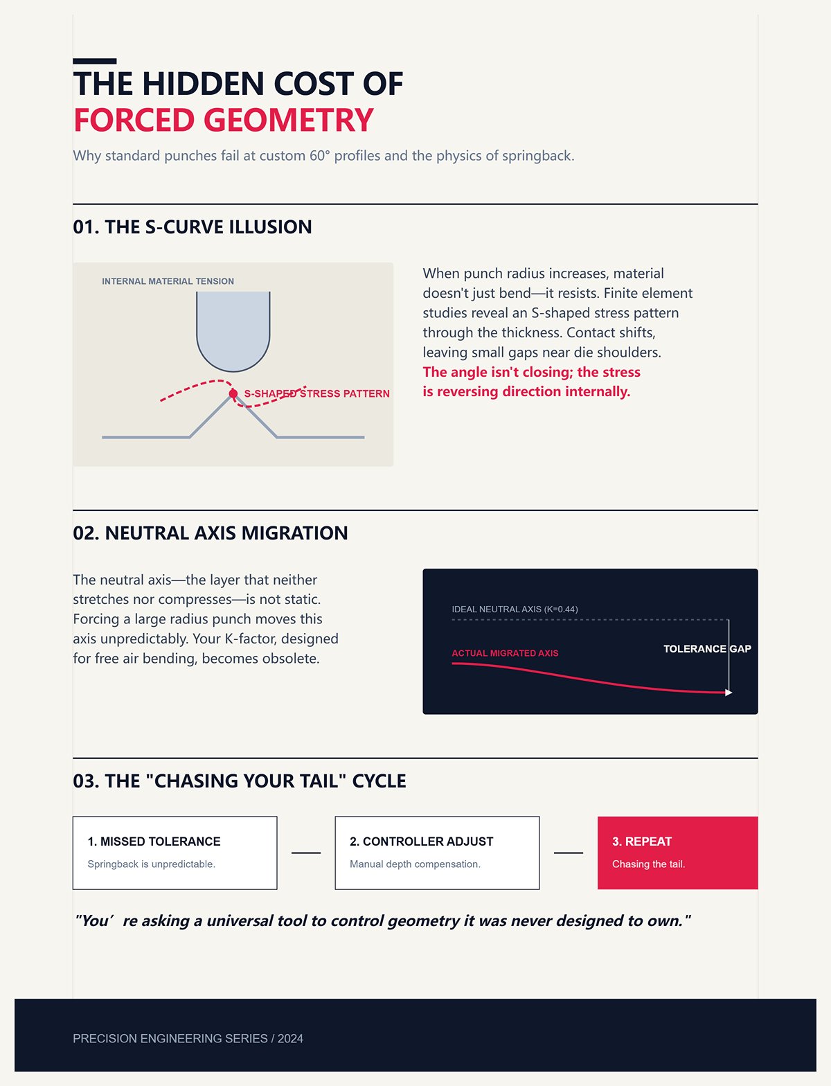
Suppose you’re trying to form a complex 60° profile in a V-die with a large punch radius. You go deeper expecting tighter angle. But finite element studies have shown something ugly: as punch radius increases, the material can form an S-shaped stress pattern through thickness. Contact shifts. Small gaps form near the die shoulders.
You think you’re closing the angle. Internally, stress is reversing direction.
The part springs back unpredictably because the neutral axis — that imaginary layer that doesn’t stretch or compress — has moved. Your K-factor assumption, built for free air bending, is now wrong. Not by a hair. By enough to miss tolerance every time.
So you compensate in the controller. Then compensate again. You’re chasing your tail.
All because you asked a universal tool to control geometry it was never designed to own.
What happens when the geometry pushes back harder?
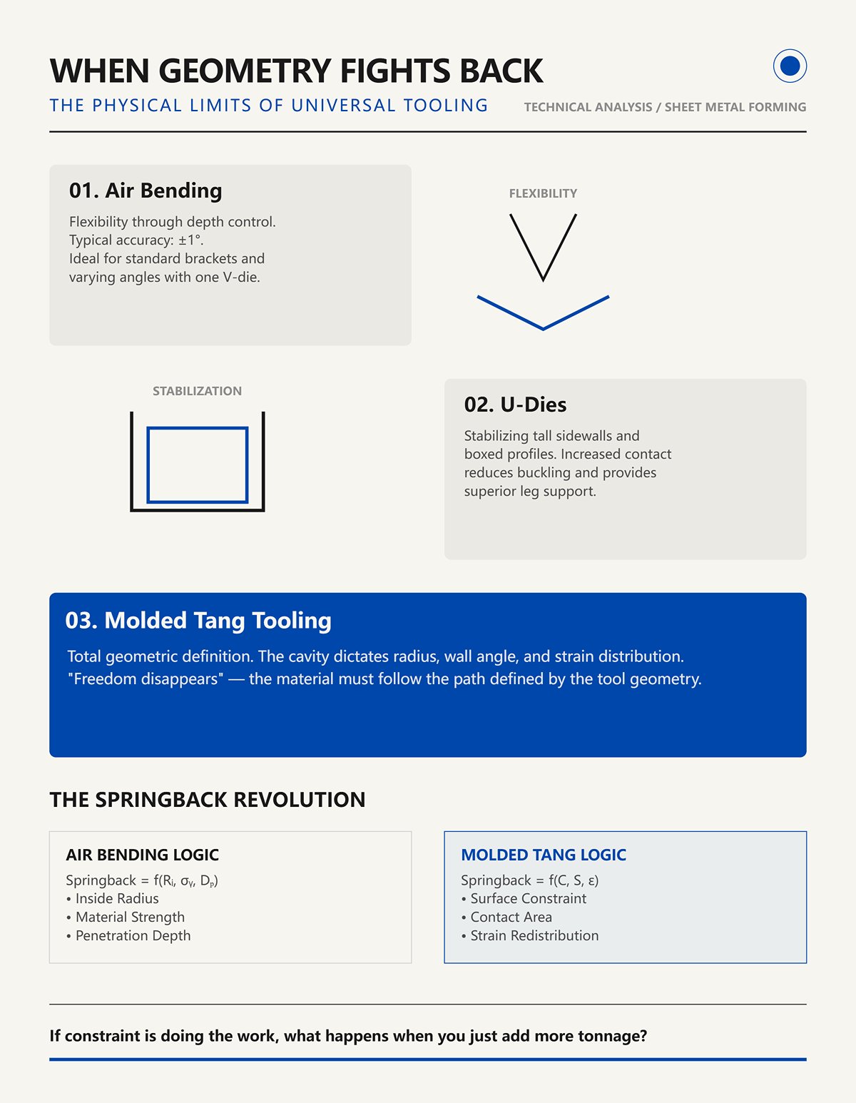
Air bending promises flexibility. One V-die can hit multiple angles with depth control. Typical accuracy? Around ±1° if you know your material. That’s fine for brackets.
But once sidewalls get tall or profiles get boxed in, the sheet wants support. U-dies prove this — they stabilize channels by supporting the legs, reducing buckling. More contact. More control.
Molded tang tooling goes further. It doesn’t just support the material; it defines its path. The cavity shape dictates radius, wall angle, even where strain accumulates. Freedom disappears.
And with it, your old springback math.
In air bending, springback is largely a function of inside radius, material strength, and penetration depth. In molded tang forming, it’s governed by constraint and surface contact. The tool geometry redistributes strain before you ever hit bottom.
That’s not a tweak to your spreadsheet. That’s a rebuild.
If constraint is doing the work, what happens when you just add more tonnage?
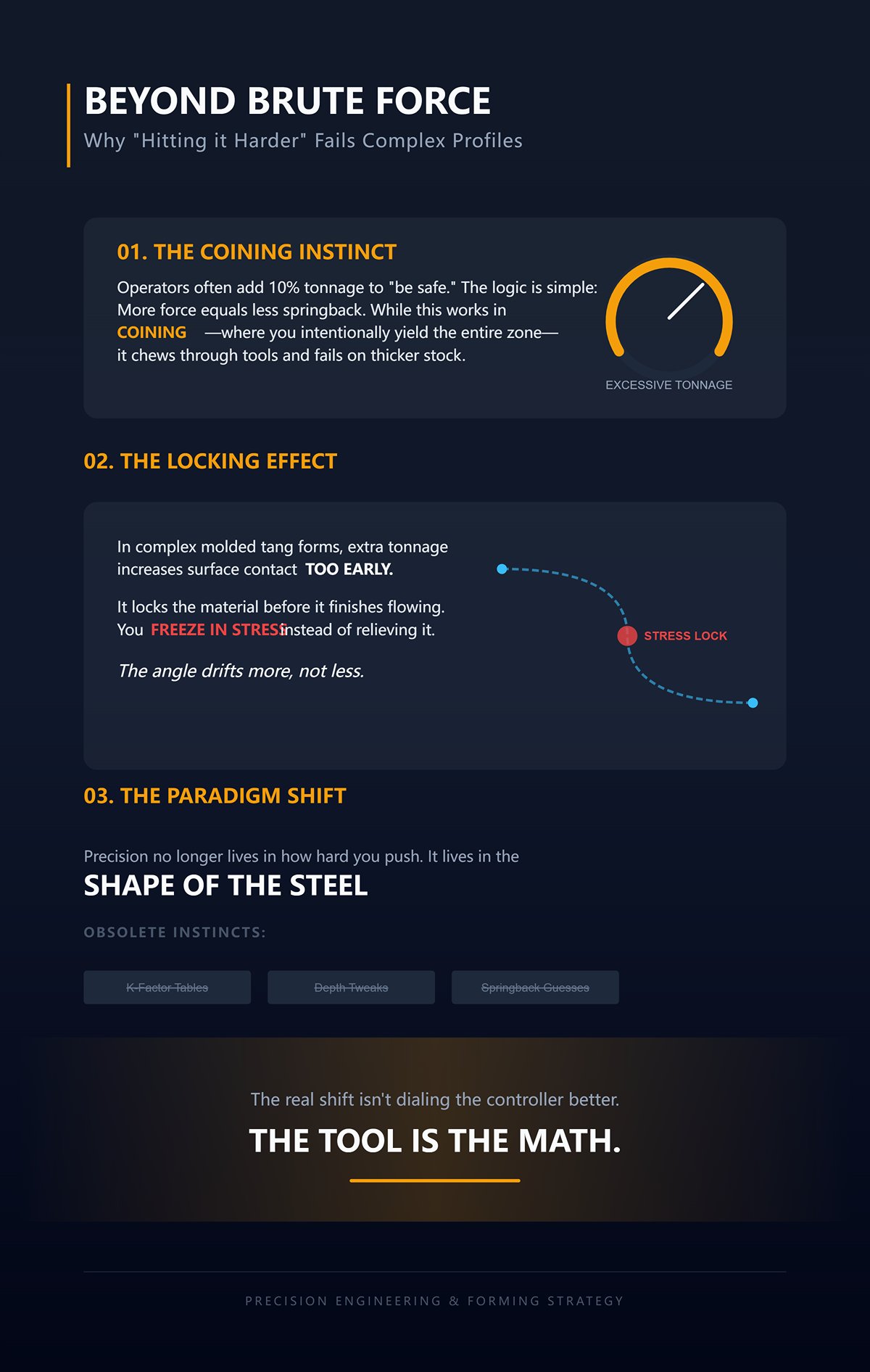
I’ve seen operators double-check tonnage charts, then add 10 percent “just to be safe.” The logic is simple: more force, less springback.
Works in coining — where you intentionally yield the entire bend zone and pin the angle. But coining chews tools and doesn’t play well with thicker stock. It’s a brute-force solution.
In complex molded tang forms, extra tonnage often increases surface contact earlier, locking material before it finishes flowing. You freeze in stress instead of relieving it. The angle drifts more, not less.
That’s the part nobody wants to hear.
Because it means precision no longer lives in how hard you push or how deep you go. It lives in the shape of the steel doing the pushing.
And if the tool owns the geometry, then your old air-bend instincts — K-factor tables, depth tweaks, springback guesses — aren’t just outdated.
They’re irrelevant.
So the real shift isn’t dialing the controller better.
It’s accepting that in molded tang forming, the tool is the math.
Picture a molded tang tool with a punch wrapped by a stripper plate, cavity walls hugging both sides of the profile, and an integrated stop that the part physically crashes into at bottom. You cycle the ram, and before you’re halfway downstroke, the sheet is already touching steel on three, four, five surfaces.
Now ask yourself: if the tool owns all those contact points, where exactly is the metal supposed to “decide” its final angle?
In air bending, you steer a loose trailer. In molded tang forming, you bolt the load into a machined cradle. The freedom disappears. And once freedom disappears, so does the old idea that the controller is in charge. What happens when the geometry pushes back harder is not a software problem — it’s a contact mechanics problem.
Set up a simple 90° air bend in 0.125 in. mild steel. Three-point contact. The sheet touches the punch tip and the two die shoulders. Everything else is open space. As you penetrate deeper, material can draw inward from the legs. The neutral axis — that layer that doesn’t stretch or compress — floats wherever the stress balance puts it. That’s why a few thousandths of depth can swing a degree. The metal is free to redistribute strain.
Now wrap that same blank inside a molded tang cavity. Add sidewalls that contact early. Add a stripper plate that drags on the surface as the punch advances. Research on constrained bending with strippers shows something critical: the friction between stripper and sheet induces tensile force along the length of the bend. Instead of the inner fibers just compressing and the outer fibers just stretching, you’re actively stretching the entire bend zone as it’s forced over the punch.
That tension resists material draw-in. The sheet can’t just slide from the legs to feed the radius. It has to elongate locally.
Reality Check: once draw-in is restricted, penetration depth no longer maps cleanly to angle. I’ve seen this scrap a $50k run.
In air bending, springback is largely a function of inside radius, material strength, and penetration depth. In constrained forming, the stress state is rewritten by friction and multi-surface contact before you ever hit bottom. The neutral axis doesn’t just “shift” — it’s pinned by geometry and tension. If the metal is being stretched over a fixed cavity while restrained from feeding, who’s really controlling the strain path?
| Section | Content |
|---|---|
| Topic | Air bending vs. constrained forming: where the material actually moves |
| Air Bending Setup | Set up a simple 90° air bend in 0.125 in. mild steel with three-point contact. The sheet touches the punch tip and the two die shoulders; everything else is open space. As penetration increases, material can draw inward from the legs. The neutral axis — the layer that doesn’t stretch or compress — floats according to stress balance. A few thousandths of depth can change the angle by a degree because the metal is free to redistribute strain. |
| Constrained Forming Setup | Wrap the same blank inside a molded tang cavity. Add sidewalls that contact early and a stripper plate that drags on the surface as the punch advances. Research shows friction between stripper and sheet induces tensile force along the bend length. Instead of only inner compression and outer tension, the entire bend zone is actively stretched as it is forced over the punch. |
| Material Behavior Difference | The induced tension resists material draw-in. The sheet cannot slide from the legs to feed the radius and must elongate locally. |
| Reality Check | Once draw-in is restricted, penetration depth no longer maps cleanly to angle. This effect can cause significant production scrap (e.g., a $50k run). |
| Springback Comparison | In air bending, springback depends largely on inside radius, material strength, and penetration depth. In constrained forming, friction and multi-surface contact rewrite the stress state before bottoming out. The neutral axis becomes constrained by geometry and tension rather than freely shifting. |
| Core Question | If the metal is stretched over a fixed cavity while restrained from feeding, what is truly controlling the strain path? |
Take a molded tang tool with a 0.060 in. machined inside radius. That radius is not a suggestion. It’s a steel fact. When the punch closes into the cavity, the sheet is forced to conform to that radius along its entire length.
In air bending, the inside radius is a byproduct — roughly 16 percent of the V-opening for mild steel as a rule of thumb. Change V-die width, change radius. Change penetration slightly, radius shifts a little. It’s flexible, which is why your K-factor tables are statistical guesses.
In a molded tang cavity, the radius is fixed. But here’s the part most people miss: fixing the radius doesn’t automatically mean fixing the angle unless the pressure distribution is right.
If you overdrive the punch past the intended stop, you start compacting the inner lattice — compressing the grain structure near the inside surface. That’s drifting toward bottoming or even coining territory, which can require five to thirty times the tonnage of air bending. Do that blindly and you can induce “negative springback,” where the part actually closes past nominal after unloading.
Sounds great until you thin the inside wall and shift the K-factor again.
So yes, fixed geometry eliminates the randomness of free air bending — but only if the cavity supports the material uniformly and the tonnage matches the design intent. Poor pressure distribution in a tight cavity can create localized overstress, thinning, and unpredictable elongation. Now your “fixed” math is broken again, just in a different way.
The lesson isn’t that molded tangs are foolproof. It’s that their accuracy lives or dies in how the cavity manages contact area, friction, and load spread. If the radius is dictated by steel, what locks the angle itself so it stops caring about ram depth?
I’ve run bottom-bend jobs on thirty-year-old brakes with sloppy encoders and still held angle. Why? Because the die was the hard mechanical limit. The controller just got me close; the tool finished the job.
A molded tang tool with an integrated stop takes that principle and tightens it. At full stroke, the part physically seats against a machined surface that defines the final wall angle. Not “approximately.” Not “based on depth.” It stops because it hits steel.
That’s backgauge independence in physical form.
If your blank is a hair long or short, air bending shows it immediately as angle variation because material can draw in differently each cycle. In a constrained cavity with an integrated stop, draw-in is already restricted and the final position is set by the stop face. Variation in ram depth of a few thousandths doesn’t change the angle once the stop is engaged — the load just increases against the tool.
But here’s the hybrid math nobody talks about: you still need enough tonnage to fully seat the part against that stop without elastic rebound holding it off the surface. Too little force and you’re floating. Too much and you’re coining unintentionally.
That means tooling design, material strength, and press capacity have to be calculated together. The controller becomes a delivery system for force and position; the tool defines the outcome.
Once you accept that the cavity fixes the radius, the stop fixes the angle, and friction fixes the strain path, the old air-bend K-factor charts aren’t just inaccurate — they’re describing a different physical world.
So if the tool is dictating radius, angle, and strain state, what does that do to your bend allowance and springback math?
I had a 0.125 in. mild steel bracket that penciled out perfectly on paper. Air-bend numbers. K-factor at 0.42. Inside radius estimated at 16 percent of a 1 in. V-opening. Bend allowance came out clean, blank cut, first hit looked good.
Except the flange came up short. Not by a hair. By 0.060 in.
Same material. Same thickness. But this time it was formed in a molded tang cavity with a 0.060 in. machined radius and sidewalls that grabbed early. The old math assumed the neutral axis would float somewhere around 42 percent of thickness from the inside. In the cavity, with friction stretching the bend zone and draw-in restricted, that neutral axis shifted outward. The material elongated more than the table predicted. More elongation means more bend allowance consumed. More allowance consumed means shorter legs.
That’s not a rounding error. That’s a different strain path.
If the tool fixes radius and angle, then the only variable left in your flat pattern math is how the material actually stretches inside that steel envelope. And that’s where the rebuild starts.
Take the classic bend allowance formula:
BA = angle × (R + K × T)
Angle in radians. R inside radius. T thickness. K the neutral axis ratio.
In air bending, K is a statistical compromise. The radius forms as a function of V-opening and penetration. The sheet can draw in from the legs as it wraps the punch. The neutral axis “finds” its own position based on relatively free deformation.
Now trap that same sheet in a molded tang cavity.
Sidewalls contact before full wrap. A stripper applies pressure on top. Friction along those surfaces induces tensile stress along the bend line. Instead of just bending, the material is being stretched over a fixed 0.060 in. radius while being prevented from feeding inward.
Mechanically, that does two things:
If your handbook says K = 0.42 and the real constrained condition behaves like 0.48 or 0.50, your bend allowance grows. On a 90° bend in 0.125 in. material with a 0.060 in. radius, that shift can eat fifty to eighty thousandths of flat length.
Reality Check: if you’re still using the handbook K-factor from your V-die job, I’ve seen this scrap a $50k run.
Could you trial-bend and back-calculate a new K like the old-timers do with V-dies? Sure. Three hits, measure, tweak, repeat. That works when the deformation mode stays consistent.
But in a molded tang, deformation consistency depends on full seating against the cavity, consistent friction, and stable tonnage. Miss one of those and your “calibrated” K drifts again. So the question isn’t whether you can tune it — it’s whether you’re tuning the right physical model in the first place.
I’ve watched operators overbend air bends to 88° so they’d spring open to 90°. Textbook move. Instead it opened up to 62°.
That wasn’t magic. That was coining creep. Once you drive deep enough in a tight cavity, you’re no longer in elastic-dominated air bending. You’re plastically compressing the inner fibers and redistributing stress through thickness. What happens when the geometry pushes back harder isn’t a gentle elastic recovery — it can flip the sign of the correction.
In air bending, springback is largely a function of inside radius, material strength, and penetration depth. So we calculate an overbend angle and command the ram to go there.
In a molded tang with an integrated stop, the final angle is defined by steel-to-steel contact. You don’t “dial in” 92° and hope it relaxes to 90°. You machine the cavity to the angle that yields 90° after unloading under full seating force.
That’s the paradox: the overbend isn’t programmed into the controller. It’s machined into the tool.
Mathematically, that means your springback term moves from a variable in the press setup to a fixed offset in the cavity angle. If material and thickness change, the cavity angle may no longer compensate correctly. Your springback factor Ks — final angle divided by loaded angle — isn’t just material-based anymore. It’s material-plus-constraint.
Ignore that, and you’ll chase your tail adjusting ram depth against a hard stop that doesn’t care what the controller thinks.
So if the angle correction lives in the tool steel itself, how much force does it take to make that correction real every cycle?
On a 4 ft air bend in 0.125 in. mild steel, you might run, say, 20 tons. The load is concentrated along a narrow punch tip and two die shoulders. Limited contact. Limited friction.
Close that same length into a molded tang cavity and you’ve got punch nose contact, sidewall contact, stripper pressure on top, and full-length seating against an integrated stop. Contact area multiplies. Friction multiplies. The material isn’t just bending; it’s being pressed into a shape.
Force equals pressure times area. Increase area, and total tonnage climbs fast.
Miss the required tonnage and the part won’t fully seat against the stop. It will elastically unload slightly off the cavity face. Now your beautifully machined overbend angle never transfers into the part. You measure 91° instead of 90°, tweak depth, and nothing changes because the stop is already engaged. You were force-limited, not position-limited.
Go too far the other way and you drift into unintended coining — five to thirty times air-bend tonnage in extreme cases — thinning the inside wall and shifting your effective K again.
That’s why recalibrating the math isn’t just about plugging a new K into a spreadsheet. It’s about linking three things into one model: constrained strain (custom K), cavity-defined overbend (tool angle), and sufficient tonnage to seat the part without crushing it.
Once you accept that the blank development, springback compensation, and press capacity are a single system in molded tang forming, the controller becomes the least interesting part of the equation.
Which means the next fight isn’t theoretical at all — it’s whether your setup and alignment are tight enough for this rebuilt math to survive first contact with the floor.
You rebuilt the math. You cut the cavity angle for springback. You verified the tonnage can seat the part without drifting into coining.
Now the only thing left that can wreck you is setup.
Here’s the hard truth: molded tang tooling doesn’t forgive slop the way air bending does. In air bending, you’re steering a loose trailer with the wheel — a little misalignment, a little ram tweak, and you can nudge the angle back. In molded tang forming, you’ve bolted the load into a machined cradle. The geometry decides. If that cradle is shifted half a millimeter, every part will be wrong in exactly the same way, at full production speed.
That’s not a small error. That’s a system error.
So the question becomes practical: if the math is right, what keeps it right on the floor?
Let’s talk about 0.5 mm.
On a molded tang cavity with sidewalls and an integrated stop, that offset doesn’t just skew an angle. It shifts where the material first contacts the wall. That changes friction distribution. That changes strain path. And since your overbend is machined into the cavity, the material will obediently form to the wrong geometry.
It won’t fight you. It will comply — incorrectly.
In a simple single-feature part, you might see a flange lean or a hole drift. In a multi-feature tang with cooling passages, reliefs, or nested bends, that half millimeter compounds. One wall engages early. Another never fully seats. Now you’ve got uneven contact pressure along the length, which means uneven springback correction built into the steel.
Reality Check: I’ve seen this scrap a $50k run. The setup tech swore the numbers were right. They were. The die wasn’t centered.
Air bending tolerates a little lateral slop because the material is free to pivot between punch and die shoulders. Molded tang forming is constrained on three sides. You’re not bending between two points; you’re pressing into a shape. Misalignment doesn’t average out — it locks in.
So how do you keep that contact behavior consistent when friction itself is part of the strain model?
In air bending, we barely think about lubrication. The sheet touches a punch tip and two die shoulders. Contact area is small. Friction matters, but it’s not steering the ship.
In a molded tang cavity, friction is part of the steering system.
As the sheet wraps and seats, sidewall drag resists draw-in. That resistance is what pushes the neutral axis outward and shifts your effective K. Change the drag, and you change the strain distribution you just spent two sections rebuilding.
Run dry on Monday, oil-heavy on Tuesday, and don’t be surprised when your “fixed” geometry starts wandering.
This is where guys start chasing their tail — tweaking ram depth against a hard stop because the angle drifted half a degree. The controller didn’t change. The steel didn’t move. The friction coefficient did.
I’m not telling you to drown it in lube. Too much lubrication can let the material slip more than your model assumes, reducing the tensile stretch along the outer fibers. Now your cavity overbend over-corrects.
Consistency beats perfection. Pick a lubrication condition. Lock it down. Document it like it’s a dimension.
Because in this process, it is.
Which brings us to the discipline part most shops rush past.
If molded tang forming is a coupled system of strain, geometry, and force, then setup has to respect that coupling.
You don’t “throw it in and hit it.”
You clamp. You gauge. You verify.
In that order.
Before you ever run material, seat the tang fully in the holder and indicate the die faces relative to the ram centerline. Not eyeball. Indicate.
You’re looking for parallelism and centering along the full working length, not just at one end. A cavity can be square at the left side and drifting at the right if the holder or bed has debris, burrs, or uneven torque on the clamps.
Clean steel matters here more than software ever will.
If the tang isn’t fully seated, your integrated stop angle — the one carrying your springback compensation — isn’t where you think it is. Now your “machined overbend” is a floating variable.
And you won’t see it until parts stack up out of spec.
With alignment confirmed, bring the ram down slowly to contact without material. Verify even contact along the cavity face using feeler stock or pressure paper if you have it.
You’re not checking angle. You’re checking seating force distribution.
Then introduce material and run a controlled hit to confirm full seating against the stop at your calculated tonnage. Watch the load curve if your press shows it. A clean rise and stable plateau tells you you’re force-limited correctly. A spike or uneven climb can signal localized contact or premature wall engagement.
Remember what happens when the geometry pushes back harder: the press must have enough authority to transfer the cavity angle into the part. If you’re shy on force, the part will spring off the stop and lie to you on the bench.
Depth numbers mean nothing if force isn’t there.
Most shops measure angle and call it good.
That’s air-bend thinking.
For molded tangs, validate three things on the first article: final angle, feature location relative to the bend line, and wall contact marks inside the cavity. Those witness marks tell you whether seating is uniform or biased.
If the angle is right but the feature shifted, your K assumption under constraint may be off — or friction isn’t what you modeled. If contact marks are heavy on one side, alignment or lubrication isn’t stable yet.
This is where the rebuilt math meets steel reality.
Get this right, and you’ve turned a fragile setup into a repeatable system. Get it wrong, and every cycle just makes scrap faster.
And once alignment, friction, and stroke are disciplined, another question creeps in — what happens when the material itself doesn’t behave the same from coil to coil?
| Step | Content |
|---|---|
| Step 1: Seating the tang and verifying die alignment | Before you ever run material, seat the tang fully in the holder and indicate the die faces relative to the ram centerline. Not eyeball. Indicate. You’re looking for parallelism and centering along the full working length, not just at one end. A cavity can be square at the left side and drifting at the right if the holder or bed has debris, burrs, or uneven torque on the clamps. Clean steel matters here more than software ever will. If the tang isn’t fully seated, your integrated stop angle — the one carrying your springback compensation — isn’t where you think it is. Now your “machined overbend” is a floating variable. And you won’t see it until parts stack up out of spec. |
| Step 2: Calibrating ram stroke for overtravel | With alignment confirmed, bring the ram down slowly to contact without material. Verify even contact along the cavity face using feeler stock or pressure paper if you have it. You’re not checking angle. You’re checking seating force distribution. Then introduce material and run a controlled hit to confirm full seating against the stop at your calculated tonnage. Watch the load curve if your press shows it. A clean rise and stable plateau tells you you’re force-limited correctly. A spike or uneven climb can signal localized contact or premature wall engagement. Remember what happens when the geometry pushes back harder: the press must have enough authority to transfer the cavity angle into the part. If you’re shy on force, the part will spring off the stop and lie to you on the bench. Depth numbers mean nothing if force isn’t there. |
| Step 3: First-article validation beyond the angle check | Most shops measure angle and call it good. That’s air-bend thinking. For molded tangs, validate three things on the first article: final angle, feature location relative to the bend line, and wall contact marks inside the cavity. Those witness marks tell you whether seating is uniform or biased. If the angle is right but the feature shifted, your K assumption under constraint may be off — or friction isn’t what you modeled. If contact marks are heavy on one side, alignment or lubrication isn’t stable yet. This is where the rebuilt math meets steel reality. Get this right, and you’ve turned a fragile setup into a repeatable system. Get it wrong, and every cycle just makes scrap faster. And once alignment, friction, and stroke are disciplined, another question creeps in — what happens when the material itself doesn’t behave the same from coil to coil? |
You dial everything in. Indicated the die. Verified seating. Locked lubrication like it was a dimension. First coil runs dead on.
Second coil comes in. Same spec on paper: 16-gauge stainless. You hit the stop, full tonnage, clean load curve. Instead it opened up to 62°.
Nothing moved on the machine. The geometry didn’t change. So what did?
When you air bend, you’ve got room to steer. Depth changes angle. The material pivots on two shoulders. If thickness creeps a few thousandths, you bump the ram and move on. The controller carries part of the burden.
Molded tang tooling doesn’t give you that steering wheel. The cavity owns the angle. The stop owns the overbend. When the tool is the math, any change in what fills that cavity becomes your problem.
That’s the Achilles’ heel.
I’ve watched a precision brake struggle with stainless that varied 0.003 inch from edge to center. Thicker in the middle, thinner at the sides. No pattern you could chase with a simple correction like “two thou equals two degrees.” Along the same bend line, one section underbent while the other over-seated.
In air bending, that inconsistency partly averages out. The sheet contacts at three points. Thicker sections resist penetration more, so you adjust depth or let the angle correction system hunt a little. It’s not perfect, but it’s adjustable.
Now put that same sheet into a molded tang cavity.
You’re no longer bending between points. You’re displacing material into a defined volume. If the sheet is 0.003 inch thicker at mid-span, it reaches the cavity walls sooner. Contact pressure spikes locally. Friction increases right there. That shifts the neutral axis differently at that location, which changes the effective K-factor along the length.
And here’s the part most folks miss: the stop doesn’t know any of that. It just says, “This is the angle.”
So the thicker section may never fully seat against the overbend face while the thinner edges do. You end up with a part that looks fine at one end and lies to you at the other.
Reality Check: I’ve seen this scrap a $50k run. The print called for tight tang symmetry. Material cert said “within tolerance.” The coil was legal. The parts weren’t.
With fixed geometry, thickness tolerance stops being a purchasing footnote and becomes a forming variable. You want molded precision? Then incoming thickness variation has to be tighter than what air bending ever demanded. Otherwise you’re fighting the metal inside a cavity you can’t adjust.
So if thickness is one axis of variability, what about the way the metal flows?
Take two blanks from the same sheet. One cut with the bend line parallel to rolling direction, one perpendicular. Same thickness. Same alloy. Same setup.
Parallel-to-grain often bends easier. Perpendicular fights you more. That’s basic metallurgy — rolling elongates grains, and bending across them means you’re stretching across more boundaries. Yield strength effectively changes with orientation.
In air bending, you feel that difference as springback. You tweak depth or angle correction. Done.
In a molded tang cavity, the story changes because the material isn’t free to find its own radius. The inside radius is largely dictated by the cavity geometry. In air bending, springback is largely a function of inside radius, material strength, and penetration depth. Here, penetration depth is fixed by the stop, and the radius is constrained by the die.
So when you rotate grain direction and yield strength shifts, the material’s resistance to being forced into that fixed radius shifts too. What happens when the geometry pushes back harder? Either you don’t reach full seating force — meaning incomplete conformity to the cavity — or you reach it with higher stress locked into the part.
I’ve seen identical tang tooling run mild steel all week, then switch to stainless without rethinking the cavity factor. Stainless work-hardens faster. It wants a larger inside radius — think 10–12 times thickness in conventional die selection, not 8. If your molded cavity was designed around mild steel flow, stainless will either fight to fill it or crack at the corner.
There is no universal cavity that ignores alloy and grain. If you don’t pre-compensate geometry for the specific material’s flow behavior, you’re back to chasing your tail with stroke adjustments that don’t truly fix the strain path.
So you lock thickness. You control grain orientation on the flat pattern. You design cavities per alloy, not per nominal gauge.
Now assume you did all that.
What happens after fifty thousand hits?
The first articles off a new molded tang tool are a thing of beauty. Crisp contact lines. Clean seating. Angles dead on because the cavity face still holds its machined overbend — maybe 88° cut in so the part springs to 90°.
Run it long enough, especially in high-strength stainless, and the cavity edges polish. Then they round. Microns at first. Then measurable.
You won’t see it with your eye. You’ll see it in the parts. They start coming off slightly open. Not wildly wrong. Just drifting.
Remember, in this system the angle lives in the steel of the die. If the overbend face wears from 88° toward 89°, you’ve just reduced your built-in springback compensation. The press still bottoms out at the same stop. The load curve still looks healthy. But the geometry has changed.
That’s the dark side of “the tool is the math.” Math can erode.
Wear also changes friction behavior. Polished walls may reduce drag, allowing slightly more draw-in before full seating. That shifts strain distribution again, nudging your effective K-factor without anyone touching a number in the controller.
Air bending tolerates some tool wear because angle comes from depth. Molded tang forming is less forgiving. You need wear inspection intervals tied to hit count and material type. Gauge the cavity angle periodically. Blue the faces and check contact patterns. Treat regrind as a dimensional change that requires revalidation of flat patterns, not just a maintenance task.
If the tool owns the precision, then tool life, incoming thickness control, and grain discipline aren’t side issues. They are the process.
And that forces the bigger question every shop eventually faces: is this level of control — on material, tooling, and inspection — worth what molded tang precision promises?
You’re asking the right question: is all this upstream policing and downstream babysitting worth it?
Here’s the part that’s non-obvious. In molded tang work, you’re not buying tighter angles — you’re buying the right to stop adjusting them.
In air bending, you live at the screen. Part comes off 91° instead of 90°? Nudge depth. Different coil? Bump correction. You’re steering a loose trailer with the wheel, correcting every sway. That works because the angle is a function of penetration and springback. In air bending, springback is largely a function of inside radius, material strength, and penetration depth. You control penetration. So you control the angle.
Molded tang tooling rips that steering wheel out of your hands.
The cavity is the angle. The stop is the depth. The overbend is machined in. If the tool was cut at 88° so the part springs to 90°, that decision is frozen in steel. When it works, it works without babysitting. When it doesn’t, you don’t tweak — you redesign. That’s the mental shift most shops never fully make.
So the real question isn’t “Is it more precise?” It’s “Do I want precision engineered into steel instead of dialed in at 10:37 a.m. by whoever’s on shift?”
Chasing angles is reactive. Designing bends is proactive.
When you chase, you’re responding to what came off the brake five minutes ago. When you design, you’re deciding — before the tool is even cut — what the neutral axis will do, where the material will thin, how the grain will react inside a fixed radius. That means your K-factor isn’t a handbook number anymore. It’s a geometry-specific constant tied to that cavity.
And that’s where most shops stumble.
They cut a molded tang tool based on nominal thickness and a “typical” K-factor, then hope the controller can clean up whatever’s off. It can’t. I’ve seen this scrap a $50k run. Once the cavity is wrong, every hit is consistently wrong. Beautifully wrong.
Reality Check: if your toolmaker skips verifying cutter diameter before finishing the cavity, or your grinding tolerance slips from true high-precision to “close enough,” you’ve baked error into the only thing that owns the angle. You won’t tune it out later. The tool doesn’t care what the controller says.
So designing bends means dragging material control, toolmaking tolerance, and flat-pattern math into the same room before steel is cut. It’s slower up front. It’s ruthless. And it forces a different question — when is that pain justified?
Here’s the test I give customers.
First: volume. If you’re running a few hundred parts a year, molded tang tooling is like buying a race engine for a delivery van. You won’t amortize the discipline it demands.
Second: tolerance stack. If the tang angle controls a downstream weld gap, seal compression, or robotic assembly window, and you’re currently burning labor nudging angles and sorting parts, then fixed geometry starts making sense. You’re not paying for angle. You’re paying to eliminate adjustment labor and variation drift.
Third: stability of the design. Hard tooling excels when the print is settled. If engineering is still “finding the right angle,” molded tang is the wrong battlefield. Changes after the fact don’t mean a new program. They mean new steel.
There’s another layer most people miss: supply chain maturity. If you can’t guarantee thickness bands tighter than what air bending tolerated, if you can’t lock grain direction on blanks, if your tool vendor can’t hold the grinding class you spec, then the tool does not truly “own” accuracy. Variability just moved somewhere you can’t see.
So is the burden justified? Only when the process around the tool is mature enough that geometry can actually do its job.
That leads to the payoff — what happens when it is?
When molded tang tooling is done right, something interesting happens.
Your press brake stops being a tuning station and becomes a replication machine.
Instead of programs with angle corrections per material lot, you build a library of tool sets tied to specific alloys, thickness bands, and grain orientations. Tool A with Material X at 0.125 in. and parallel grain. Tool B for the stainless variant. Each one validated, documented, locked.
Now your K-factor isn’t theoretical. It’s empirical and frozen to that cavity. Your springback isn’t an adjustment; it’s machined overbend. Your operator isn’t chasing his tail — he’s loading parts into a machined cradle that dictates the result.
That’s the new lens I want you to carry forward: molded tang precision isn’t about squeezing tighter numbers out of the same mindset. It’s about moving precision upstream into design and tooling so the machine’s job becomes boringly consistent.
Air bending teaches you to think in corrections.
Molded tang forming forces you to think in commitments.
And once you accept that the commitment lives in steel, not on the screen, the question shifts from “Can I tweak this?” to “Did I engineer this right?”


