

I watched a 200-ton brake miss a 90° bend by two degrees on 3/16-inch HSLA. Brand-new machine. CNC crowning. Laser angle check. The screen said 90.0°. The part said 92°.
The operator blamed tonnage. The supervisor blamed the program. The steel just sat there, holding its shape like a stubborn apprentice who heard you—and decided to answer back.
That gap between the screen and the steel is where precision actually lives—and closing it requires more than raw tonnage; it demands CNC-controlled bending systems designed for repeatability, compensation, and integration into real production workflows. Solutions like the 100% CNC-based bending systems from CN-HAWE, detailed on their press brake solutions page, are built for high-end sheet metal applications where elastic behavior, automation, and angle consistency must align on every stroke.
A 200-ton brake doesn’t know whether you slid in 50 ksi A36 or 70 ksi HSLA. It only knows force and position. Yield strength—the stress where steel stops behaving elastically and starts taking a permanent set—isn’t something the ram can feel. It’s something you calculate.
I’ve seen shops buy bigger machines to “solve” angle inconsistency. More force. Faster servos. Tighter backgauge repeatability. And they still chase half-degree corrections all shift long. Because the machine can repeat position within thousandths, but it can’t erase springback. It can’t normalize residual stress near a weld seam you didn’t anneal. It can’t fix a bad die choice you made before the ram even moved.
High tonnage bends the part. It doesn’t guarantee where it settles after it springs back.
So when the controller says 90°, and the part says 92°, what exactly just happened?
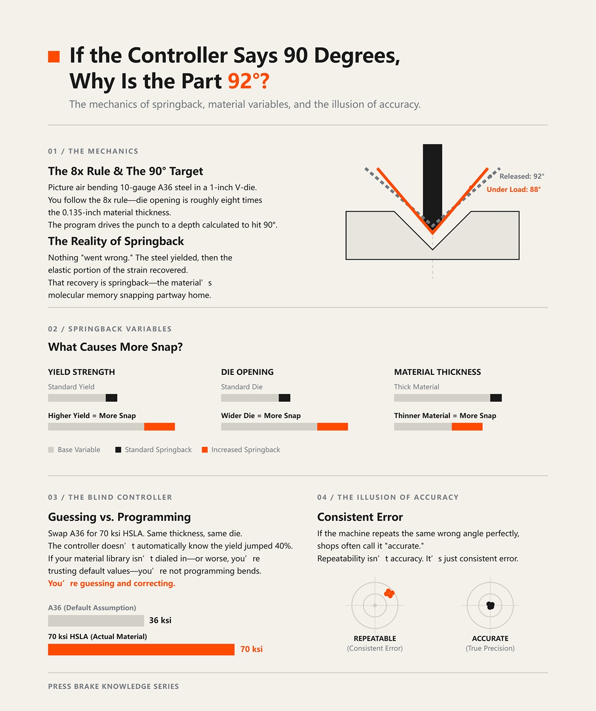
Picture air bending 10-gauge A36 in a 1-inch V-die. You follow the 8x rule—die opening about eight times material thickness—so roughly 1-inch is right for 0.135-inch stock. The program drives the punch to a depth calculated to hit 90°.
Under load, you hit 88°. Release the pressure, and the part relaxes to 92°.
Nothing “went wrong.” The steel yielded, then the elastic portion of the strain recovered. That recovery is springback—the material’s molecular memory snapping partway home. Higher yield strength? More snap. Wider die opening? More snap. Thinner material? More snap.
Now swap that A36 for 70 ksi HSLA, same thickness, same die. The controller doesn’t automatically know the yield jumped 40%. If your material library isn’t dialed in—or worse, you’re trusting default values—you’re not programming bends. You’re guessing and correcting.
And here’s where shops fool themselves: if the machine repeats the same wrong angle perfectly, they call it “accurate.” Repeatability isn’t accuracy. It’s just consistent error.
So what else is stacking the deck before the ram even touches steel?
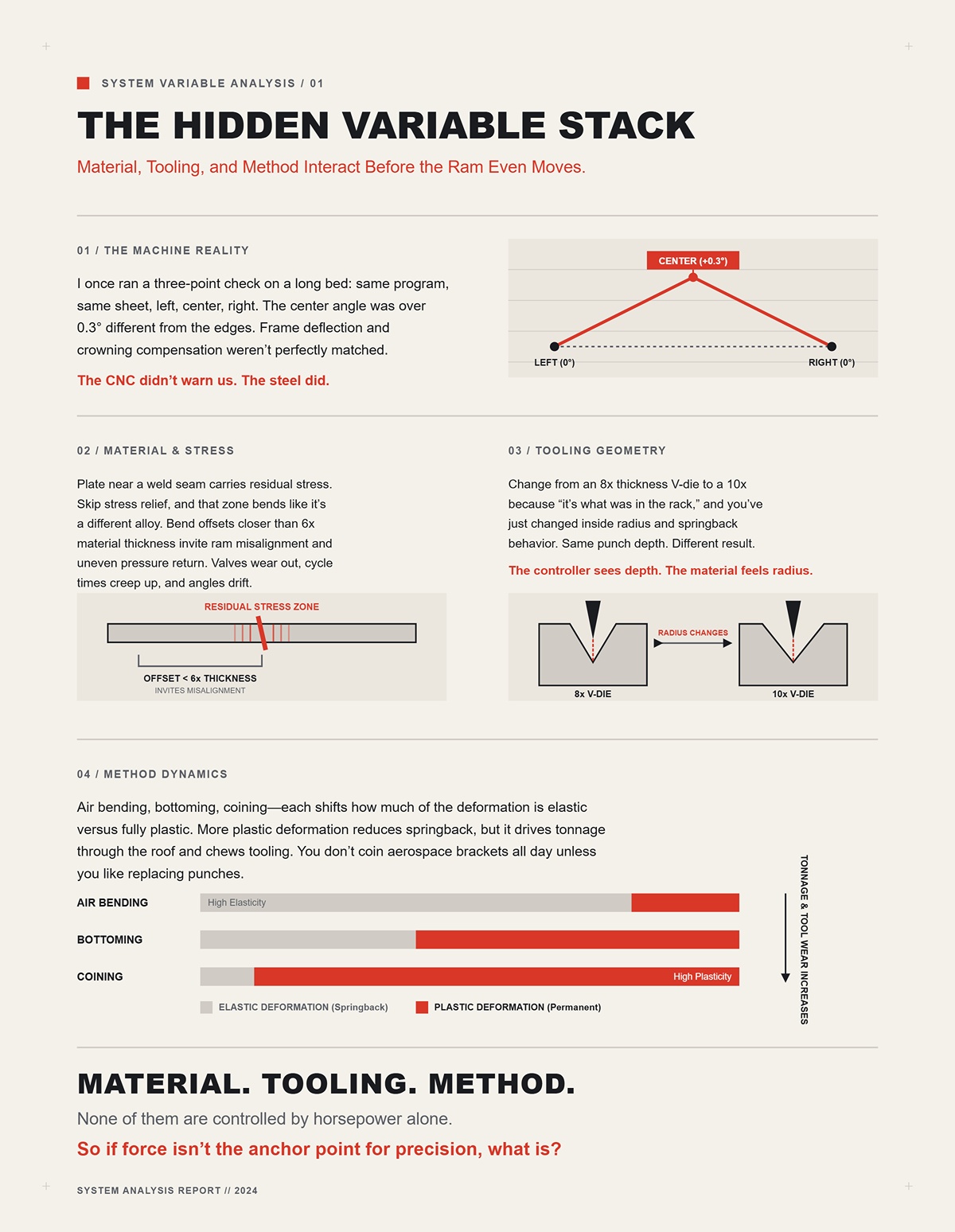
I once ran a three-point check on a long bed: same program, same sheet, left, center, right. The center angle was over 0.3° different from the edges. Frame deflection and crowning compensation weren’t perfectly matched. The CNC didn’t warn us. The steel did.
Now layer in real production conditions. Plate near a weld seam carries residual stress. Skip stress relief, and that zone bends like it’s a different alloy. Bend offsets closer than six times material thickness, and you invite ram misalignment and uneven pressure return. That’s not theory—that’s valves wearing out and cycle times creeping up while angles drift.
Tooling geometry matters just as much. Change from an 8x thickness V-die to a 10x because “it’s what was in the rack,” and you’ve just changed inside radius and springback behavior. Same punch depth. Different result. The controller only sees depth. The material feels radius.
Method ties it together. Air bending, bottoming, coining—each shifts how much of the deformation is elastic versus fully plastic. More plastic deformation reduces springback, but it drives tonnage through the roof and chews tooling. You don’t coin aerospace brackets all day unless you like replacing punches.
Material. Tooling. Method. None of them are controlled by horsepower alone.
So if force isn’t the anchor point for precision, what is?
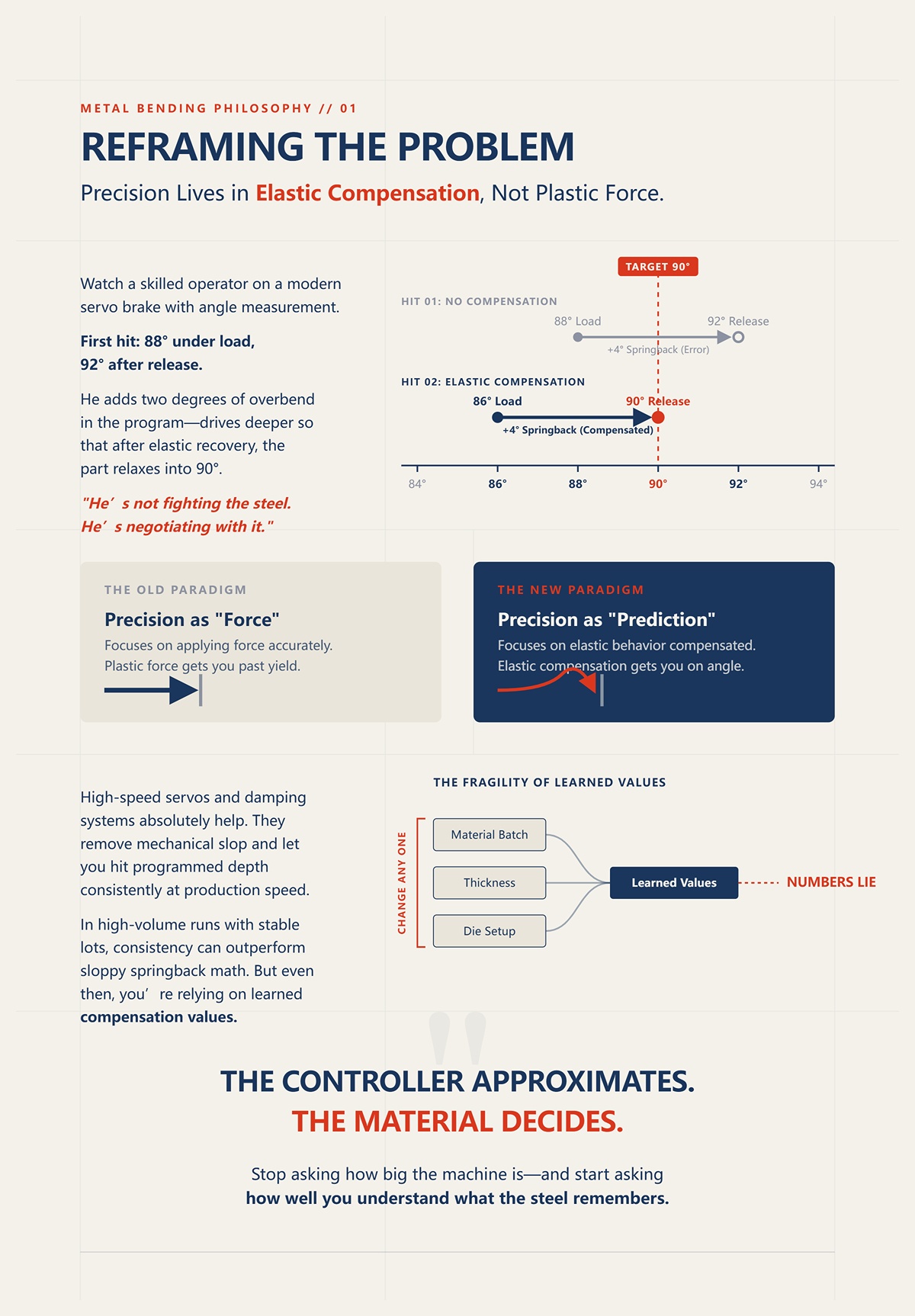
Watch a skilled operator on a modern servo brake with angle measurement. First hit: 88° under load, 92° after release. He doesn’t reach for more tonnage. He adds two degrees of overbend in the program—drives deeper so that after elastic recovery, the part relaxes into 90°.
He’s not fighting the steel. He’s negotiating with it.
That’s the shift I want you to make: stop seeing precision as “force applied accurately” and start seeing it as “elastic behavior predicted and compensated.” Plastic force gets you past yield. Elastic compensation gets you on angle.
High-speed servos and damping systems absolutely help. They remove mechanical slop and let you hit programmed depth consistently at production speed. In high-volume runs with stable material lots, that consistency can outperform sloppy springback math. But even then, you’re relying on learned compensation values tied to a specific material batch, thickness, and die setup. Change any one, and the old numbers lie.
The controller approximates. The material decides.
And the moment you accept that, you stop asking how big the machine is—and start asking how well you understand what the steel remembers.
Last winter we ran 0.125-inch 17-4PH on a brand-new machine. Program said 90°. First hit opened to 94° after release. Same die we’d used all week on 304 stainless. Same depth. Different outcome. The only thing that changed was the yield strength sitting inside that sheet.
You want to land on angle the first time? Then stop treating yield like a fixed number in a material library and start treating it like the gatekeeper of elastic memory. Springback isn’t a mystery—it’s elastic strain recovering after you’ve pushed past yield. The higher the yield strength relative to how much plastic strain you actually impose, the harder it snaps back. That’s not philosophy. That’s stress-strain curve math.
Most controllers store tensile strength because it’s printed big on the cert. But tensile strength is the peak before fracture. Springback is decided much earlier—right when you cross yield and how far you go beyond it. If you’re programming compensation off the wrong part of the curve, you’re negotiating with a ghost.
So which number on that mill cert is actually fighting your punch?
Take mild A36. Yield might sit around 36 ksi, tensile around 58–70 ksi. That’s a wide gap. You’ve got room for plastic deformation before necking. When you air bend it in an 8x die, you push well past yield in the outer fibers. Plenty of plastic strain. Springback is manageable because the plastic zone dominates the elastic core.
Now compare that to high-strength alloys where the yield-to-tensile ratio climbs toward 0.9. I’ve seen certs where 80 ksi yield is chasing 88 ksi tensile. That means the material starts to yield and almost immediately approaches its limit. There’s less plastic cushion between “permanent set” and “fracture.” You’re bending closer to the edge. The elastic portion is a bigger share of the total strain. More snap on release.
That’s why 17-4PH—yield around 950–1050 MPa, tensile just north of 1100 MPa—behaves like a disciplined but unforgiving apprentice. It yields high, hard, and doesn’t give you much post-yield stretch. Great for precision parts in service. Tough in the brake. If you program it like 304 because the tensile numbers look similar on paper, you’ll under-compensate and chase angles all shift.
And here’s where shops fool themselves: if the machine repeats the same wrong angle perfectly, they call it “accurate.” The controller did its job. You fed it the wrong battlefield map.
So tensile strength tells you how it dies. Yield strength tells you how it springs back. Which one matters at 88° under load?
I once cut two brackets from the same 4×8 sheet of 0.187-inch 5052. Same nest, same thickness, same program. One bent across the grain. The other bent with it. First one relaxed to 90.2°. Second one opened to 91.1°. Customer tolerance was ±0.5°. One passed. One didn’t.
Rolled sheet isn’t isotropic—that’s just a clean word for “it doesn’t behave the same in every direction.” During rolling, grains elongate along the rolling direction. Bend across the grain, and you’re forcing those elongated structures to stretch differently than when you bend parallel to them. Effective yield strength shifts slightly with direction. Not dramatically. Just enough to matter when you’re chasing tenths of a degree on aerospace brackets.
On thin stock in wide V-dies—say 16-gauge in a 1-inch die—the plastic zone is already shallow. Small directional changes in yield behavior show up as measurable springback differences. If your flat pattern guy rotates parts for better sheet yield and doesn’t flag bend direction, your compensation table just got blind-sided.
Steel remembers how it was rolled long before it remembers how you bent it.
So if yield varies by alloy and by direction, what happens when it varies within the same heat lot?
We ran a batch of 10-gauge HSLA where the first pallet bent clean at +1.5° overbend. Second pallet—same spec, same supplier—needed +2.2° to settle at 90°. Certs were within range. Thickness mic’d the same. What changed? Likely micro-variations in chemistry and cooling rate that nudged yield upward a few ksi and shaved ductility.
You won’t see that on the surface. But you’ll feel it when the part opens another half degree.
Ductility—the material’s ability to deform plastically before fracture—controls how much of your bend strain becomes permanent versus elastic. Lower ductility means you approach tensile strength quickly after yield. The plastic region shrinks. Elastic recovery becomes a larger fraction of total strain. That’s why high-carbon steels, with tensile barely above yield, can crack instead of gracefully springing back. In those cases, the problem isn’t too much memory. It’s no forgiveness.
Now flip it around. Extremely ductile metals can localize strain—necking in tension tests shows this clearly. In bending, if strain concentrates unevenly through thickness because of tooling radius or surface condition, your assumed uniform yield behavior goes out the window. Your model said one thing. The outer fibers did another.
So how do you program for that?
You don’t trust a catalog number. You bend a test coupon from the actual lot, in the actual die, at the actual thickness. Measure under load if you can. Record the real overbend required. Build your compensation around observed yield behavior, not brochure tensile strength. Then lock down grain direction and die selection with the 8x thickness rule so you’re not stacking new variables on top of a moving target.
The controller can approximate. The steel decides.
And once you accept that yield is a moving target—shifting with alloy, direction, and ductility—you’re ready to ask a sharper question: how does the bending method itself change how much of that elastic memory survives the hit?
I’ve got a 0.125-inch 5052 coupon on the bench, bent in a 1-inch V-die—right on the 8x thickness rule. Under load it reads 88°. Ram comes up. It relaxes to 92.4°. That’s over 4° of springback, and that’s not a typo. I’ve seen some aluminum lots push past 5° when the inside radius runs large.
Here’s what’s actually happening in air bending.
The sheet only touches the tooling in three places: punch tip and the two die shoulders. The angle is created by penetration depth, not by forcing the material to conform to a fixed cavity. That means most of the thickness is in a mixed state—outer fibers past yield, inner core still elastic. When you release pressure, that elastic core unloads and pulls the bend open. How far? Exactly as far as the yield behavior of that specific lot allows.
Air bending is a negotiation with elasticity.
Change nothing but the material—from A36 to 70 ksi HSLA in the same 8x die—and your required overbend jumps. The geometry didn’t change. The tonnage barely changed. The yield did. That’s your multiplier. In mild steel you might overbend 1–2°. In high-strength material, 3° isn’t unusual. In some aluminums, more.
And here’s where shops fool themselves: if the machine repeats the same wrong angle perfectly, they call it “accurate.” The CNC only knows depth and angle math based on assumed yield. It cannot feel that this pallet runs 6 ksi higher than the last one. If you treat air bending like a button-pusher process, you’ll chase angles all shift because the three-point contact leaves a large elastic core alive inside the bend.
So what happens if we reduce that elastic core on purpose?
Same material. Same thickness. Now instead of stopping short in the V, you drive the punch deeper so the part makes near-full contact with the die faces. Not coining—just bottoming. The punch angle is slightly more acute than the die angle, so the material is forced closer to the target geometry.
Under load, the metal is no longer floating between three points. It’s pressed along the die walls. More of the cross-section is pushed past yield because you’re plastically deforming it to match the die angle, not just flexing it into space.
Springback drops. Not to zero. But it drops.
If air bending that 0.125-inch steel needed 2° of overbend, bottoming might cut that to under 1°. The multiplier shrinks because the elastic portion of the thickness shrinks. You’ve overpowered more of the molecular memory.
But don’t kid yourself—bottoming is not springback-free. The punch and die still don’t compress the material through its entire thickness like a forging operation. There’s still elastic strain stored in the core. That’s why bottoming setups often use tooling ground a degree or two acute. They’re pre-compensating mechanically because they know some recovery is coming.
And here’s the part that upsets the “it’s all about machine quality” crowd: bottoming can make an older, looser press look better than it is. By forcing the material into the die angle, you reduce reliance on precise depth control. You’re substituting tonnage and contact for intelligence.
That works—up to a point.
You pay in higher forming pressure, more tool wear, visible die marks on cosmetic parts, and more load on the machine frame. I’ve seen shops bottom 10-gauge stainless all day and then wonder why their ram parallelism drifts over the year. Steel doesn’t forget. Neither does your brake.
So if bottoming reduces springback by overpowering more yield, what happens when you go all the way?
Now we’re not negotiating. We’re crushing.
Coining drives the punch tip into the material with enough pressure to plastically deform the entire bend zone through thickness. Tonnage can jump five to ten times over air bending. You’re not just forming an angle—you’re imprinting it. The inside radius becomes the punch radius because the material yields completely at the contact zone.
Elastic memory has nowhere to hide.
Springback becomes almost negligible because the elastic core has been largely eliminated in the bend area. The material can’t “relax” back to a wider angle; it has already been pushed beyond yield across most of its thickness at that radius.
That’s why coining shows up in tight-tolerance aerospace brackets where ±0.25° actually matters and volumes justify the load. He adds two degrees of overbend in the program—drives deeper so that after elastic recovery, the part relaxes into 90°—in air bending. In coining, that compensation nearly disappears because the geometry is mechanically locked in.
But you don’t get that precision for free.
The tonnage requirement can approach the limits of the machine. Tooling sees extreme contact stress. Surface finish can suffer. Maintenance intervals shorten. If you’re coining parts that could have been air bent with smart compensation and proper 8x die selection, you’re trading brainwork for brute force—and beating up a half-million-dollar asset in the process.
Coining makes sense when the cost of angle variation exceeds the cost of tonnage and wear. It’s a strategic decision, not a macho one.
So now you’ve seen the spectrum: air bending leaves a large elastic core, bottoming reduces it, coining nearly eliminates it. Same material. Same yield behavior. Different amounts of molecular memory allowed to survive.
If method changes how much memory remains, then the next lever isn’t force.
It’s geometry.
Put a sheet of 0.125-inch 5052 in a 1-inch V-die and air bend it to 90°. You’ll likely see 3–4° of springback. Swap nothing but the die to a 0.75-inch opening and run the same depth program. Angle changes. Tonnage changes. Springback changes. Same machine. Same operator. Same material.
So what moved?
The interface. The V-die and punch are where force turns into strain distribution through the thickness. In air bending, that distribution is set by three points: punch tip, die shoulders. Change the V-width and you change the bend radius that forms naturally. Change the radius and you change how much of the cross-section is pushed past yield and how much is left elastic in the core. That elastic core is the “memory” we’ve been talking about.
Tooling geometry doesn’t just shape the part. It decides how much of the apprentice remembers the lesson.
And if you think the CNC can compensate for a bad die choice, you’re back to being a button-pusher with expensive toys.
I’ve watched a new guy grab a 1-inch die for 0.125-inch steel because “that’s what we always use.” He wasn’t wrong. He just didn’t know why.
The 8× rule says your V-die opening should be about eight times material thickness for mild steel in air bending. For 0.125-inch, that’s 1.000 inch. It’s not folklore. It’s geometry and strain control. At roughly 8×, the inside bend radius that forms naturally is about 0.16 × V-opening. So a 1-inch die gives you roughly a 0.160-inch inside radius. That radius produces a predictable strain gradient: plastic near the inside surface, elastic toward the neutral axis, manageable springback for common yields.
Now change the material to 70 ksi HSLA at the same thickness. Yield is higher. That means for the same radius, a smaller portion of the thickness goes plastic before the stress falls below yield. Your elastic core grows. Springback increases.
Here’s where shops fool themselves. They keep the 8× die because “thickness didn’t change,” then chase angles all shift with depth tweaks.
The 8× rule was built around mild steel behavior. It is a starting point, not a commandment.
For higher-yield materials, tightening the die opening—say moving from 8× down to 6×—reduces the natural inside radius. Smaller radius increases surface strain. More of the thickness crosses yield. The elastic core shrinks. Springback drops. But tonnage rises fast, and surface strain climbs toward fracture limits. In aluminum, especially across the grain, you can buy yourself a crack chasing angle stability.
So the real question isn’t “What’s the thickness?” It’s “What yield am I managing, and how much plastic penetration through the thickness do I need?”
Ignore the 8× rule entirely and I promise the steel will educate you the hard way. Treat it blindly and it’ll do the same.
Which brings us to what most people never calculate.
Take that same 0.125-inch sheet in a 1.000-inch die. Now tighten the die to 0.900 inch. That’s a 10% reduction in opening.
Air-bend tonnage is inversely proportional to die width. Roughly speaking, T ∝ 1/V. Shrink V by 10%, and tonnage doesn’t drop—it climbs about 11%. That’s the clean math.
But that’s not the whole story.
Because the smaller die also reduces the formed inside radius. Smaller radius means higher strain at the inner surface. Higher strain means you’re pushing deeper into plastic deformation. To reach the same angle, especially in higher-yield material, you often drive deeper than the simple 1/V equation predicts. Real-world force jumps can feel like 20–40% depending on material and angle target.
I’ve seen a shop swap from a 1-inch to a 0.875-inch die on 10-gauge A36 to “tighten up the angle.” The press brake load meter went from comfortable to flirting with the machine’s rated tonnage. Same part print. Same thickness. Different geometry. The machine didn’t get weaker. The die got narrower.
Now layer in method. Bottoming already demands roughly 1.5× air-bend tonnage. Coining can demand 5×. If you tighten the die and escalate the method at the same time, you can stack multipliers until you’re stressing tooling, pins, and frames. And if the material lot runs high on yield, your neat spreadsheet numbers evaporate.
This is how a brand-new machine ends up blamed for “angle inconsistency” when the real issue is a die choice that swung force and strain distribution beyond what the process window could tolerate.
And force is only half the interface.
I once saw a bracket spec’d with a near-zero inside radius on 0.090-inch 304 stainless. The programmer picked a sharp punch to “lock in” the angle and fight springback. The first ten parts looked fine. The eleventh showed a hairline crack at the inside bend.
Why?
A sharp punch tip concentrates strain at the inner surface. Strain in bending is approximately thickness divided by twice the inside radius. Drive the radius down and that surface strain spikes fast. In high-strength or low-ductility materials, you can exceed elongation limits before the rest of the thickness has meaningfully yielded. You get a crack before you get stability.
On the other end, go too large on punch radius—classic radius bending—and you reduce peak surface strain so much that a thick elastic core survives. Springback becomes unpredictable. In multi-bend parts without return flanges, 2° per bend can stack into 8° across four bends. Geometry that was “safe” on a single hit becomes a tolerance disaster in sequence.
So what’s the move?
Match punch radius to material ductility and target inside radius, not to some macho idea of “sharp equals accurate.” In air bending, the punch radius should be equal to or smaller than the natural radius formed by the chosen V-die. That keeps contact conditions stable without forcing extreme strain. If you need a tighter inside radius than the die naturally forms, you don’t just jam in a razor punch—you reassess die width, method, or even move to controlled bottoming with compensated punch angle.
I’ve seen a 7° springback case solved not by cranking tonnage or narrowing the die, but by using an 83° punch with precision bottoming so the plastic flow matched the target geometry. Geometry did the compensation, not brute force.
The die sets the span. The punch sets the strain concentration. Together, they decide how much of the thickness yields and how much remembers.
And once you start pushing tonnage and narrowing windows to control that memory, you’re not just negotiating with the material anymore—you’re loading the machine structure itself, which brings us to what happens when the frame, not the die, becomes the weak link.
A 12-foot bend in 0.125-inch 5052, air-formed in a 1-inch V-die on a 175-ton brake. Center reads 90°. The last 6 inches on both ends read 92°. Same program. Same punch. Same operator.
That isn’t springback wandering around. That’s the machine sagging under load.
When you drive tonnage up—tight die, high-yield lot, deeper penetration to tame that elastic core—you’re not just negotiating with the sheet anymore. You’re loading the ram and bed like a beam in bending. Steel frame, pinned at the ends, force in the middle. Basic mechanics: beams deflect most at center. If the machine deflects downward in the middle, the punch penetrates less relative to the die at center than at the ends. Less penetration means a more open angle.
So why did the center come out tight in that example?
Because the shop had mechanical crowning dialed in from the last job—overcompensated for lighter material. The bed was pre-cambered upward. Under heavier load, the frame sag and the pre-load didn’t match. The deflection curve shifted, but the correction didn’t. The result wasn’t random. It was predictable.
And here’s where shops fool themselves: if the machine repeats the same wrong angle perfectly, they call it “accurate.”
Repeatability isn’t geometry. It’s just consistent error.
If the next step is to speak with the team directly, Contact us fits naturally here.
If tooling geometry governs strain distribution through the thickness, frame deflection governs how evenly that strain is applied along the length. Miss either one, and your negotiation with the material’s memory falls apart before springback even enters the conversation.
Picture a simple model. Twelve feet between side frames. Ram pushing down at 120 tons total, distributed across the bend line. Treat it like a loaded beam: deflection at center increases with the cube of length and directly with load. Double the tonnage, and deflection doubles. Increase bend length, and deflection climbs fast.
Now layer in material reality.
A 10% increase in tensile strength demands roughly 10% more force to hit the same angle. If thickness climbs 10%, tonnage can jump closer to 20% because bending force scales with thickness squared. That extra force doesn’t just change penetration—it changes frame shape under load.
If your crowning system was set for the lighter lot, the new load profile produces a different deflection curve. The center opens up while the ends stay tight, or vice versa depending on how you preloaded the bed.
I’ve seen 70 ksi HSLA swapped in for A36 on the same print. Same 8× die. Same programmed depth. The operator added two degrees of overbend in the program—drives deeper so that after elastic recovery, the part relaxes into 90°. Ends hit fine. Center sat 1.5° open across ten feet. He kept chasing depth. All he did was increase overall tonnage and exaggerate the deflection mismatch.
The material wasn’t misbehaving. The frame was.
Crowning isn’t about fixing bad programming. It’s about matching the machine’s elastic curve to the load curve before you ever argue with springback.
So what system actually follows that moving target?
I’ve run both.
Mechanical wedge crowning is honest but static. You dial in a pre-load—basically forcing the bed into a slight upward bow before the hit. Under the “expected” tonnage, the bed flattens out. That works beautifully if your assumptions are right.
But assumptions collapse when the lot changes.
A 10% jump in strength means 10% more force. That means 10% more deflection. Mechanical wedges don’t know that. They can’t adjust under load. If your center comes out open, you stop, shim, re-dial, and try again. Production hates that.
Hydraulic crowning systems push oil into zones along the bed to create compensation. Better ones allow adjustment during the cycle. As tonnage builds, pressure in the crowning cylinders can be tuned to match actual load, not assumed load. The table stays closer to planar contact with the sheet while force ramps.
That matters because air bending force is not constant through the stroke. It spikes as the angle closes. A static wedge matches only one point on that curve. A responsive hydraulic system can track it.
But let’s keep our heads straight.
Even hydraulic crowning is still an approximation. Most systems compensate in zones, not continuous points. Seal wear, oil temperature, valve response—they all shift behavior over time. If the deflection curve of the frame and the compensation curve of the system don’t match point-by-point, you’re still approximating.
You’re still negotiating with the steel’s memory using a machine that has its own.
Which brings up the mistake that turns temporary deflection into permanent damage.
I walked into a shop with a brand-new machine that “couldn’t hold angle across 10 feet.” Center always open. Ends always tight. They had started bottoming 10-gauge stainless in a narrow die to kill springback—stacked multipliers: tighter V, higher yield, bottoming method.
They were running near rated tonnage every cycle.
Over time, the bed developed a permanent upward bow at the ends and a slight sag in the middle. We checked with a straightedge and feeler gauges. It wasn’t dramatic. A few thousandths. That’s all it takes.
Think about the strain math. In air bending, a few thousandths of penetration difference can shift angle by a degree or more depending on die width. If the bed takes a permanent set—what guys call “canoeing”—you can dial crowning all day and never truly flatten the system. You’re compensating for damage, not elastic behavior.
Frames are designed to deflect elastically within rated tonnage. Exceed that repeatedly, and you move from elastic to plastic deformation in the machine itself. Now the machine has memory too.
And unlike the sheet, you don’t get to scrap it and pull another blank.
If tooling geometry pushes tonnage to control springback, and crowning tries to neutralize elastic deflection, then the real discipline is knowing where elastic ends and permanent distortion begins.
Because once the brake remembers how you abused it, every negotiation with the material starts from a warped baseline.
You want the safe tonnage window and the right crowning setting?
You earn it with test bends, not guesses.
Rated tonnage on the side of the frame tells you where the machine yields permanently. Your real window is narrower: the range where the frame stays elastic, the bed stays straight under load, and the material yields just enough to relax into spec after springback. That window shifts when yield strength shifts, when grain direction flips, when someone swaps A36 for 70 ksi and forgets to tell you.
Steel remembers.
If you don’t measure how this lot behaves in this die on this machine, you’re negotiating blind with two memories at once—the sheet’s and the brake’s. So the strategy isn’t “add two degrees and hope.” It’s controlled probes: short parts, measured penetration, verified angles, tonnage watched like a hawk. You’re mapping the elastic border before you run production across it.
That’s the difference between operating a press brake and controlling a forming process.
I don’t start with a full-length 10-foot part.
I cut a 3-inch-wide strip from the same sheet, same grain direction, and I bend it in the exact die we’ll run—8× material thickness for the V-opening unless there’s a documented reason to break that rule. If it’s 0.125-inch material, I’m in a 1-inch V. Not because the book says so, but because I’ve seen what happens when guys tighten the die to “fight springback” and quietly double their tonnage.
Here’s the math the button-pushers skip: air-bend tonnage scales with thickness squared and drops as die width increases. Narrow that V by 10–15%, and force climbs fast. That extra force doesn’t just close angle. It bends the frame harder. Now your crowning setting is wrong before you’ve even looked at springback.
So I run the test strip to 90° programmed.
Then I measure what it relaxes to.
If it opens to 92°, I know I need roughly 2° of overbend in this setup. He adds two degrees of overbend in the program—drives deeper so that after elastic recovery, the part relaxes into 90°. But I’m not done. I watch the tonnage graph during the hit. If I’m already at 85–90% of rated capacity on a short strip, I know a full-length bend will push deflection and maybe flirt with permanent set if crowning isn’t right.
Fifteen minutes. Three strips. Across-grain and with-grain if the print allows both.
That beats four hours of chasing angles on finished parts while production stands around blaming the steel.
You need starting points, not folklore.
Mild steel in a proper 8× die? One to two degrees of springback in typical thicknesses. 5052-H32 aluminum? Two to four, sometimes more if you’re across the grain. 304 stainless in air bending? Three to five is common. High-strength low-alloy at 70 ksi? I’ve seen seven degrees on a clean setup.
Those aren’t promises. They’re opening bids.
The mechanism is simple: higher yield strength means a larger elastic core through the thickness during air bending. More elastic core means more recovery when load comes off. You can bottom or coin to crush that elastic zone, yes—but coining can demand five to ten times the tonnage of air bending. On a standard brake, that’s how you turn elastic frame deflection into permanent canoeing.
And once the bed takes a set, your “solution” becomes the new problem.
So I treat those degree ranges as guardrails. If my test strip in 0.125-inch 304 opens four degrees in a 1-inch V, that’s normal. If it opens eight, something changed—material temper, wrong die width, bad punch radius. The test tells me whether I’m inside expected behavior before I ever touch a production blank.
You don’t eliminate variation.
You box it in.
Modern controls carry material libraries. Some even read angle in real time and adjust depth on the fly.
Useful tools.
But they are still approximations built on average yield values and assumed friction. Change grain direction, surface finish, or lot chemistry, and the real springback curve shifts. I’ve watched laser angle systems get confused by brushed stainless and chase a ghost two degrees off reality.
And here’s where shops fool themselves: if the machine repeats the same wrong angle perfectly, they call it “accurate.”
I trust the table when my test strips confirm it. If the control says stainless at this thickness in this die needs 3° overbend and my strip relaxes from 87° to 90°, good. We’re aligned. If it says 3° and I measure 5°, I override it without apology. The controller can’t feel yield strength drift. You can measure it.
The CNC is a calculator.
You are the process owner.
When you build compensation from measured behavior—short strips, known die geometry, verified tonnage—you stop reacting to springback and start predicting it. And once you can predict it inside the machine’s elastic limits, the conversation shifts from “How hard can I hit it?” to something more serious.
What kind of operator do you want to be: someone who runs parts, or someone who controls outcomes?
You want prediction to survive second shift.
Not in your head. Not in your notebook. In the process itself — so the part comes off at 90° whether you’re there or not.
That’s the line between running a machine and controlling a forming system.
A brand-new machine won’t save you from a drifting process. I’ve watched shops bolt a six-figure brake to the floor, load the OEM material table, and assume precision comes pre-installed. Two months later, day shift hits 90°, night shift hits 92°, and everyone blames the steel. What actually changed was not force. It was discipline. No locked die rule. No documented test strip results. No agreed-overbend tied to that lot and grain direction. Just tribal memory.
Steel is a stubborn apprentice with a long memory. If you don’t write down how it behaved in that 1-inch V on 0.125-inch 304 across the grain, the next operator is negotiating from scratch.
So how do you make prediction repeatable instead of personal?
Because the largest error source in most shops isn’t backgauge drift or crowning mismatch. It’s unmeasured springback.
Ignore elastic recovery and you’re gambling two degrees or more. That’s not a setup nuisance. That’s scrap on aerospace parts with a half-degree tolerance.
Yield strength is the gatekeeper here. Higher yield means a thicker elastic core during air bending. Thicker elastic core means more recovery when load comes off. The machine doesn’t “see” that shift unless you tell it. And yield strength moves from lot to lot — even inside the same spec band.
You can’t standardize force and hope for precision.
You standardize how you respond to elastic behavior.
That means every new material lot, thickness, or grain orientation triggers the same controlled probe: short strip, correct V by the 8× rule unless engineering says otherwise, measured angle after relaxation, tonnage observed. The result isn’t just “needs 3° overbend.” It’s documented: material heat, die opening, punch radius, programmed depth, actual springback.
Now you’re building a material response library that belongs to your shop, not a generic CNC table.
But documentation alone doesn’t stop drift between operators, does it?
I’ve seen a manual brake with a sharp operator out-hold a poorly-calibrated CNC by a full degree all day long.
Not because the machine was better.
Because the process was tighter.
Here’s what that looks like in practice:
And here’s where shops fool themselves: if the machine repeats the same wrong angle perfectly, they call it “accurate.”
Repeatability without validation is just automated scrap.
High-end controls with in-process angle correction can chase springback in real time. Good systems. I’d run one. But even they rely on baseline assumptions about yield and friction. If your foundation data is sloppy, the correction loop just oscillates around the wrong target faster.
The manual brake wins in bad shops because it forces attention.
So the question becomes: how do you build that attention into the system so it doesn’t depend on personality?
Most operators think in terms of final angle.
Process controllers think in terms of elastic penetration.
When you air bend, you’re not forming 90°. You’re driving to a calculated depth that creates a specific elastic-plastic distribution through the thickness. He adds two degrees of overbend in the program—drives deeper so that after elastic recovery, the part relaxes into 90°. That depth — not the displayed angle — is the real control variable.
Lock that in, and angle becomes a byproduct.
Here’s the framework I expect a lead hand to run:
Now prediction lives in measured penetration and documented response, not in who’s at the control.
Control the elastic phase, and the plastic result follows—every single time.
That’s the lens I want you to carry forward: precision isn’t about pushing harder or buying smarter software. It’s about treating elastic recovery as the primary variable and designing your shop’s habits around it.
Once you see bending as management of elastic memory instead of pursuit of force, you stop asking, “Can the machine hit it?”
You start asking, “Have we defined the material’s behavior tightly enough that it can’t miss?”


