

A 10‑foot sheet of 14‑gauge slides into the die. The new guy squints at the tonnage chart, bumps the pedal harder than he needs to, and waits for the steel to surrender. It does.
Then it springs back two degrees and scuffs the paint where the punch kissed too hard.
If this were just a metal folder in the dictionary sense—something that “folds metal”—more force would mean more certainty. But the first thing you learn on the floor is that the metal never simply obeys. It negotiates.
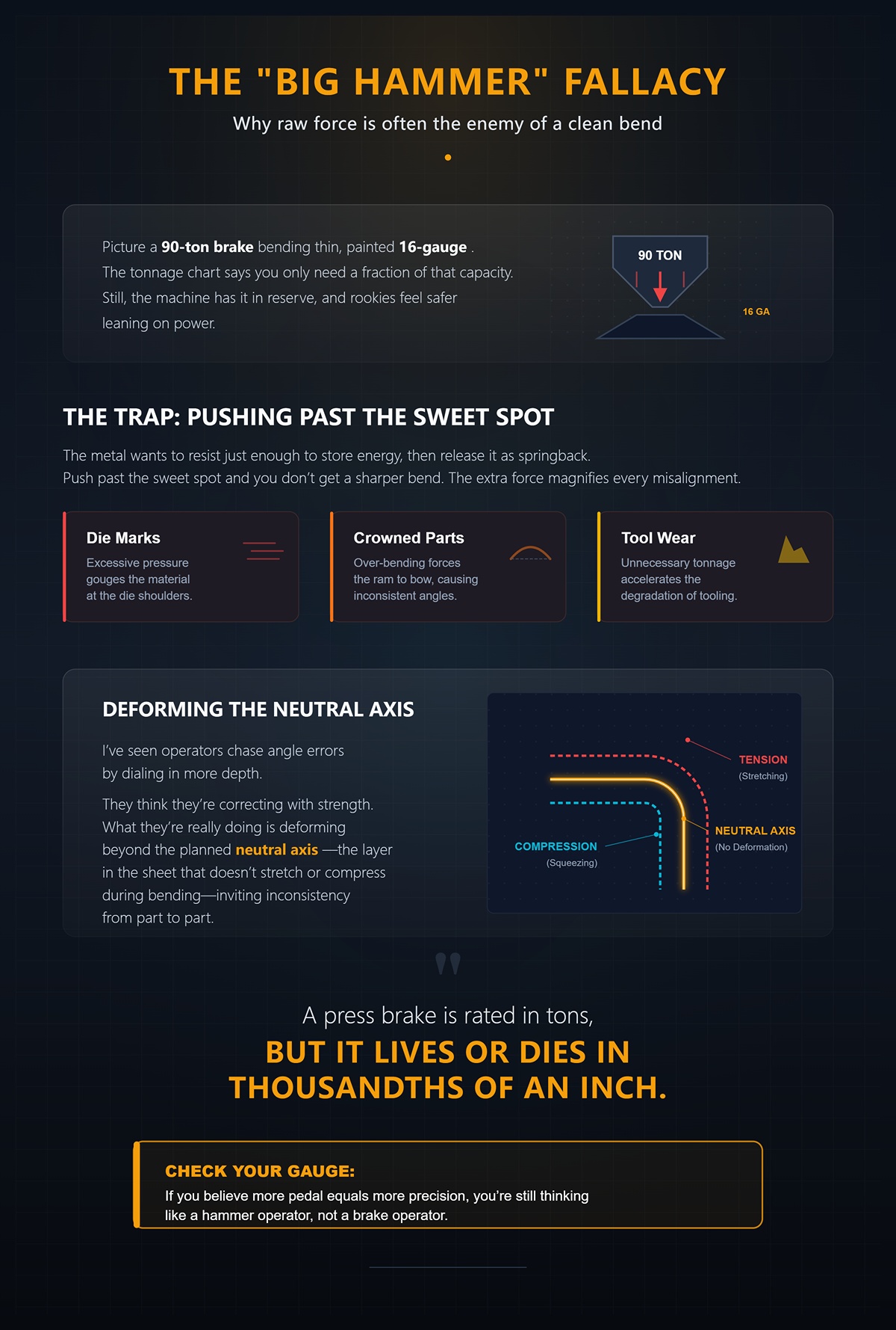
Picture a 90‑ton brake bending thin, painted 16‑gauge. The tonnage chart says you only need a fraction of that capacity. Still, the machine has it in reserve, and rookies feel safer leaning on power.
Here’s the trap: the metal wants to resist just enough to store energy, then release it as springback. Push past the sweet spot and you don’t get a sharper bend—you get die marks, crowned parts, and accelerated tool wear. The extra force doesn’t improve geometry; it magnifies every misalignment in the setup.
I’ve seen operators chase angle errors by dialing in more depth. They think they’re correcting with strength. What they’re really doing is deforming beyond the planned neutral axis—the layer in the sheet that doesn’t stretch or compress during bending—and inviting inconsistency from part to part.
A press brake is rated in tons, but it lives or dies in thousandths of an inch.
Check Your Gauge: If you believe more pedal equals more precision, you’re still thinking like a hammer operator, not a brake operator.
Let’s slow the moment down.
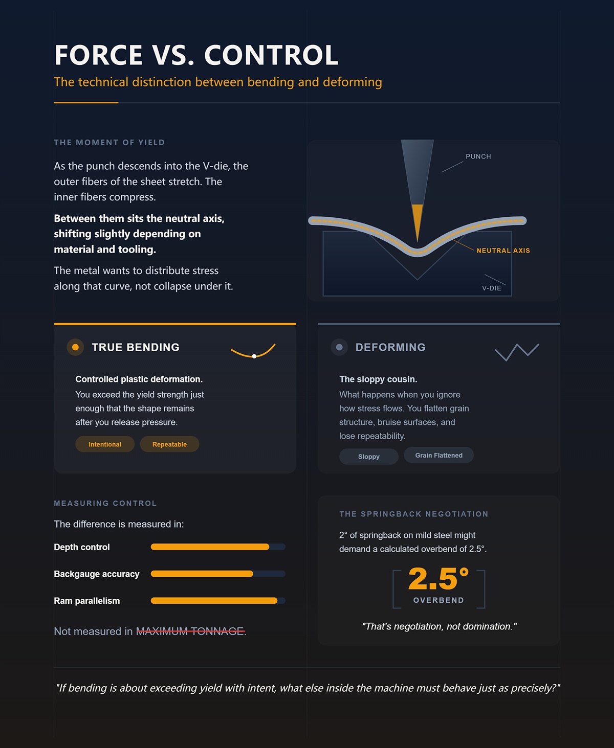
As the punch descends into the V‑die, the outer fibers of the sheet stretch. The inner fibers compress. Between them sits that neutral axis, shifting slightly depending on material and tooling. The metal wants to distribute stress along that curve, not collapse under it.
True bending is controlled plastic deformation: you exceed the yield strength just enough that the shape remains after you release pressure. Deforming, the sloppy cousin, is what happens when you ignore how stress flows. You flatten grain structure, bruise surfaces, and lose repeatability.
The difference is measured in depth control, backgauge accuracy, and ram parallelism—not in maximum tonnage. Two degrees of springback on mild steel might demand a calculated overbend of two and a half degrees. That’s negotiation, not domination.
If bending is about exceeding yield with intent, what else inside the machine must behave just as precisely?
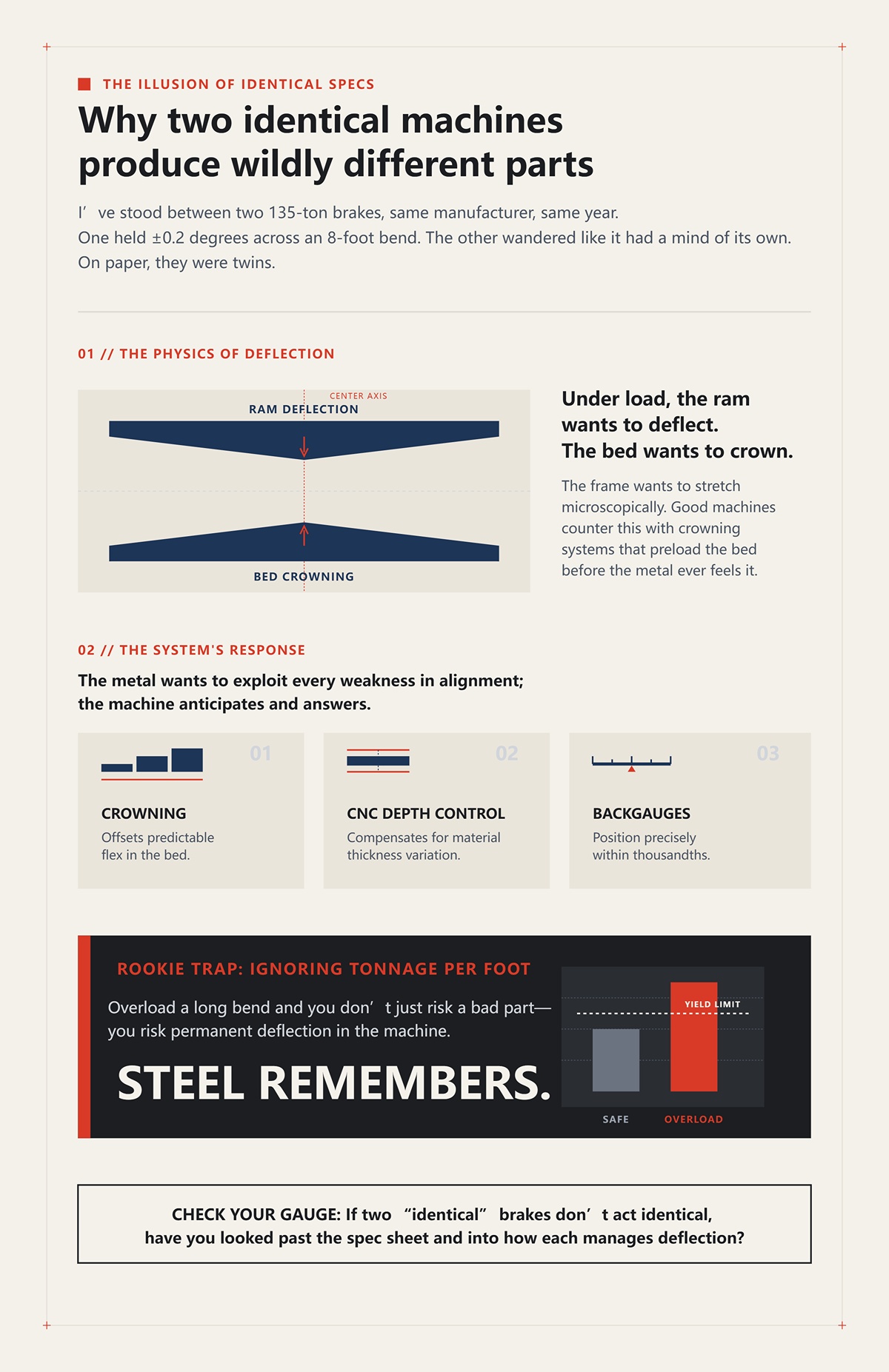
I’ve stood between two 135‑ton brakes, same manufacturer, same year. One held ±0.2 degrees across an 8‑foot bend. The other wandered like it had a mind of its own.
On paper, they were twins.
Under load, though, the ram of any brake wants to deflect in the middle. The bed wants to crown. The frame wants to stretch microscopically. Good machines counter this with crowning systems—mechanical or hydraulic adjustments that preload the bed to fight deflection before the metal ever feels it.
That’s where the system shows itself. CNC depth control compensates for material thickness variation. Backgauges position within thousandths. Crowning offsets predictable flex. The metal wants to exploit every weakness in alignment; the machine anticipates and answers.
Rookie trap: ignoring tonnage per foot. Overload a long bend and you don’t just risk a bad part—you risk permanent deflection in the machine. Steel remembers.
Check Your Gauge: If two “identical” brakes don’t act identical, have you looked past the spec sheet and into how each manages deflection?
Call it a metal folder and you picture a hinge and a shove. Stand at the controls long enough and you see something else.
The press brake coordinates three conversations at once: force applied through the ram, motion guided by CNC axes, and material behavior shaped by grain direction, thickness tolerance, and springback. Change one variable and the others respond. The metal wants to return to flat; the machine counters with calculated overbend. The frame wants to flex; the crowning system preloads against it. The operator wants speed; the physics demand patience.
That’s not brute force. That’s force management under constraint—like playing chess against an opponent that remembers every move.
And if the whole game is about how the metal stores and releases stress, what exactly happens inside the sheet the instant the punch makes contact?
Stand at the side of the brake and watch closely. The punch hasn’t even buried itself into the V‑die yet—just first contact—and the sheet already dimples under the tip. No angle formed. No dramatic fold. Just a shallow indentation where stress begins to concentrate.
That instant matters.
The outer surface under the punch tip feels tensile stress first—it wants to stretch. The inner surface, pressed toward the die shoulders, wants to compress. Between them sits the neutral axis, the thin internal layer that neither stretches nor compresses. It doesn’t stay politely centered; it shifts toward the inside radius as load increases. The metal wants to move that axis to protect itself, redistributing strain where the grain can tolerate it.
At this stage, everything is elastic. Elastic means temporary. You could stop the ram early, release pressure, and the sheet would flatten out as if nothing happened. That’s the metal’s memory—its internal lattice structure resisting permanent rearrangement.
Keep descending.
The stress at the outer fibers eventually exceeds yield strength—the point where the material stops behaving like a spring and starts flowing plastically. Now you’re rearranging grain structure. Now you’re spending the metal’s memory, not just borrowing it. This transition from elastic to plastic isn’t a cliff; it’s a narrow ridge. Cross it cleanly and you get repeatable bends. Hover too shallow and you get wild springback. Drive too deep and you bruise tooling and shift the neutral axis unpredictably.
This is why a brake with ±0.01 mm ram repeatability still produces parts that vary five times that in the real world. Thickness variation, grain direction, tool wear—they all alter where that elastic‑plastic transition actually occurs. The machine may hit the same depth every cycle, but the material does not respond identically.
The first move in this chess match happens before the angle is visible.
Check Your Gauge: When the punch first touches the sheet, are you thinking about angle—or about where yield actually begins?
Bend a piece of mild steel to a measured 93 degrees under load. Release the ram. It opens to 90.
That three‑degree difference is not error. It’s stored elastic energy escaping.
As the punch forces the sheet into the die, the outer fibers stretch past yield, but deeper layers closer to the neutral axis may remain elastic. When you release pressure, those elastic zones recover, pulling the bend open slightly. The metal wants to return toward flat because part of it never agreed to stay bent.
Air bending—the most common method—relies on this behavior. The punch never bottoms out; it controls angle by penetration depth. That means springback must be predicted and compensated with calculated overbend. On mild steel, maybe 1–3 degrees. On high‑strength material, more. On thin sheet, often proportionally higher than thick plate.
Here’s the part that flips rookie intuition: thicker material often shows less percentage springback than thin sheet. Thin stock has a larger portion of its cross‑section behaving elastically relative to the plastic zone. So that flimsy 20‑gauge can demand more aggressive overbend than 10‑gauge plate. The metal wants to snap back harder when it hasn’t committed much thickness to plastic flow.
There is another path: bottoming or coining. Drive the punch deep enough to press the material firmly into the die angle, crushing much of that elastic memory. Springback drops close to zero. Sounds perfect—until you calculate tonnage. Bottoming can require several times the force of air bending and often dedicated tooling angles. That’s not just energy; that’s frame stress, tool wear, and setup cost. Precision bought with brute load is expensive.
So we overbend instead—not because it’s crude, but because it’s efficient. We accept that the metal will take a few degrees back and plan the move ahead of time.
The new guy squints at the tonnage chart, bumps the pedal harder than he needs to, and waits for the steel to surrender. But surrender isn’t the goal. Prediction is.
If springback is the metal’s memory asserting itself, why does that memory change so dramatically between alloys?
Take two sheets, same thickness: one mild steel, one 304 stainless. Set up identical tooling. Bend both to the same programmed depth.
The stainless opens more when you release.
Stainless steel has higher yield strength and a wider gap between yield and ultimate tensile strength. That means it can store more elastic energy before and even during plastic deformation. The metal wants to stretch and still keep a strong pull toward its original lattice alignment. So springback increases, and required tonnage rises accordingly.
Aluminum plays a different game. Lower modulus of elasticity than steel. That means for the same stress, it deflects more elastically. It feels soft under the punch, but it springs back aggressively relative to its yield. The metal wants to move easily—and then recover more than you expect.
Grain direction adds another layer. Bend perpendicular to the rolling direction and the material typically tolerates tighter inside radii. Bend parallel, and cracking risk increases because you’re asking elongated grains to open along their length. The metal wants to split along its weakest orientation.
This is where “standard tonnage per foot” charts become starting points, not guarantees. They assume nominal thickness, average properties, and fresh tooling. Real coils vary. A few thousandths thicker across a 10‑foot bend can shift tonnage requirements enough to change angle outcome. That’s why experienced operators adjust depth based on test bends, not blind faith.
Check Your Gauge: When you switch from mild steel to stainless, do you change only the tonnage—or your expectation of how the material will remember the bend?
Picture a cross‑section of the bend under magnification. Outer grains elongated. Inner grains compressed and slightly buckled. Somewhere between them, a boundary where elastic behavior fades into plastic flow.
Your job is to position that boundary deliberately.
Too shallow, and most of the thickness remains elastic. The bend looks right under load but opens unpredictably. Too deep, and you force excessive plastic deformation, thinning the outer radius and risking micro‑cracks—especially in high‑strength or improperly oriented grain. The metal wants to protect its internal structure; push recklessly and it answers with fracture or inconsistency.
The sweet spot is where enough of the cross‑section has yielded to anchor the shape, but not so much that you damage integrity or overload the machine. That balance depends on inside radius selection, die opening width (often around 8 times material thickness for air bending in mild steel), and accurate depth control.
This is why bending uses far less energy than machining. We’re not cutting material away; we’re persuading it to flow just past yield. Efficient, yes. But that efficiency comes with sensitivity. Small shifts in thickness or tool wear move the elastic‑plastic boundary, and your angle drifts.
The press brake, then, is not crushing steel into submission. It is positioning stress with intent, so that when pressure releases, the material settles exactly where you predicted.
And if the metal’s memory and grain dictate so much of the outcome, what kind of machine architecture is required to manage those forces without introducing its own errors?
Two press brakes sit side by side on a shop floor. Both rated at 135 tons. Same tooling. Same operator. Same 10‑foot strip of 11‑gauge mild steel.
One holds ±0.5° across the length after a single correction. The other drifts a degree at the center and needs chasing. Same tonnage sticker. Different result.
That’s your first clue that force capacity and force control are not the same animal.
But the first thing you learn on the floor is that the metal never simply obeys. It negotiates. It pushes back through springback, shifts the neutral axis as it yields, and amplifies any inconsistency in how the ram arrives at bottom. If your drive system can’t meter force and position through that elastic‑plastic transition, you’re not bending — you’re gambling.
So the architecture question isn’t “How many tons?” It’s “How does this machine deliver those tons through the stroke?”
Check Your Gauge: If two brakes share the same tonnage rating, what part of the stroke — approach, contact, or bottom — do you actually control on yours?
Picture an old mechanical brake: flywheel spinning, clutch engaged, crankshaft turning that rotational energy into vertical ram motion. Once you trip it, the ram completes the cycle. No hesitation. No mid‑stroke rethink.
That’s production muscle.
Mechanical systems shine in repetition. If you’re stamping the same shallow bend thousands of times in thin stock, that fixed stroke becomes an advantage. Bottom dead center — the lowest point in the crank rotation — is mechanically defined. Each hit lands in nearly the same physical spot because the geometry of the crank decides it, not fluid pressure or servo feedback.
Now here’s the trap.
The stroke is fixed. The energy is stored in that spinning flywheel. Once engaged, you cannot feather the last few thousandths of an inch to compensate for a coil that came in 0.004″ thicker. The metal wants to resist a little more today than it did yesterday. The mechanical brake doesn’t care. It drives through bottom dead center with whatever energy the flywheel carried.
If you’re air bending, that lack of variable stroke control becomes a liability. You’re trying to stop at a precise depth where elastic memory will spring you back to target. But the crank doesn’t “pause and measure.” It commits. Overbend errors turn into angle scatter.
And there’s the rookie trap: chasing angle by increasing tonnage on a mechanical brake when the real problem is stroke inflexibility. The new guy squints at the tonnage chart, bumps the pedal harder than he needs to, and waits for the steel to surrender. On a mechanical system, that can mean slamming into the dead point with more energy than the frame or tooling appreciates.
Mechanical brakes reward sameness. They punish variability.
Check Your Gauge: Are your jobs identical enough that a fixed stroke works in your favor — or are you asking a crankshaft to negotiate with springback?
Stand in front of a hydraulic brake during a test bend. The ram descends fast, slows near contact, then creeps into the work as pressure builds. You can stop it mid‑stroke. Reverse it. Nudge it deeper by thousandths.
That controllability changed the industry.
Hydraulic cylinders convert fluid pressure into linear force. Pressure builds only as resistance builds. The metal wants to stiffen as it crosses yield; the hydraulic system responds by increasing pressure to maintain motion. That feedback loop — resistance matched by pressure — is what makes air bending practical at scale.
Now add the real‑world detail: most electric brakes today top out under roughly 300 tons. If you’re bending thick plate or long parts with wide dies, you need raw force beyond that ceiling. Hydraulics can scale up — larger cylinders, higher pressures, longer beds. That’s why heavy fabrication shops still rely on them.
But hydraulics have their own temperament.
Fluid compresses slightly. Seals wear. Temperature shifts viscosity. A minor internal leak can cause pressure drift during the dwell at bottom, which translates into angle inconsistency. I’ve seen a machine hold angle perfectly in the morning and open up half a degree by late afternoon because oil temperature changed response time. The metal wants consistency; the fluid system sometimes negotiates differently hour to hour.
Variable stroke control made hydraulics dominant because you can approach the elastic‑plastic boundary deliberately. Yet that precision depends on a healthy, well‑maintained pressure system. Ignore that, and your “control” becomes theoretical.
Check Your Gauge: When your angles drift, do you blame the operator — or have you checked oil condition, seal wear, and thermal stability?
Now watch a modern electric press brake run a 14‑gauge stainless part. Servo motors drive ball screws directly connected to the ram. No oil. No valves. Just torque converted to linear motion with encoder feedback measuring position in microns.
The ram moves down. Stops exactly where commanded. Holds without pressure fluctuation because there is no fluid column to compress.
That direct drive is why shops report faster cycle times and significant energy savings — power is drawn mainly during motion, not continuously to maintain hydraulic pressure. One fabricator I know replaced most of their hydraulic fleet with electric machines for light‑to‑medium work, cut energy consumption nearly in half, and improved repeatability on thin stainless parts. But they kept one hydraulic brake on the floor for high‑tonnage plate.
That’s the reality behind the “revolution.”
Electric systems excel where precision of depth equals precision of angle — thin to mid‑thickness materials, shorter beds, moderate tonnage. The servo can micro‑adjust depth to compensate for springback variation from sheet to sheet. The metal wants to rebound differently each batch; the servo can respond in fine increments without overshoot.
But force ceilings are real. Deep box bends in thick material demand sustained high tonnage over longer strokes. Today, hydraulics still own that territory. Electric isn’t replacing hydraulic across the board — it’s redefining what “precision first” work looks like.
Hybrid setups are becoming common because shops are realizing something uncomfortable: the machine type shapes the kind of accuracy you can promise customers.
Check Your Gauge: Are you choosing a machine for maximum tonnage on paper — or for the type of force control your most demanding parts actually require?
Run a long 12‑foot bend in 10‑gauge on a hydraulic brake without active crowning compensation. You’ll often see the center open slightly compared to the ends because the frame deflects under load. The machine structure stretches; the bed bows. The metal wants uniform stress; the frame introduces its own.
Now try the same on a high‑precision electric brake designed for lighter work. You may get exceptional depth control — but if the job exceeds its tonnage comfort zone, you’re operating near capacity, where any overload risk forces conservative programming.
Here’s the point most brochures won’t say: drive system and frame design together define your practical accuracy ceiling. A mechanical brake can repeat bottom dead center all day—but only for jobs that tolerate fixed stroke energy. A hydraulic brake can handle massive loads—but only as accurately as its pressure stability and deflection compensation allow. An electric brake can place the ram with surgical precision—but only within its tonnage envelope. If you’re evaluating where that ceiling should sit for your work mix, a CNC press brake engineered with verified frame rigidity and predictable force control—like those from CN-HAWE—becomes the practical next step; explore how these capabilities come together in a modern press brake built for repeatable accuracy without operating on the edge.
Accuracy is not just a matter of encoder resolution. It’s the intersection of force delivery method, structural rigidity, and how gracefully the system responds when the metal wants to push back harder than expected.
In this chess match, your drive system is your opening strategy. Choose poorly, and you spend the rest of the game compensating for a machine that adds its own uncertainty to the material’s memory.
So if drive architecture determines how force is delivered and limited, what happens when we zoom in from power source to geometry — to how the ram stays parallel, how the backgauge positions, and how the frame counters its own deflection under load?
Roll a 12‑foot strip of 10‑gauge under the punch, call up your program, and let the machine hit 180 tons. The angle reads 90° at the ends. In the center, it’s 90.7°. Same depth. Same force. Different result.
Nothing changed in the drive system. What changed was the shape of the machine under load.
When you push that much force through the ram, the side frames stretch microscopically and the bed bows upward in the middle. Steel under stress doesn’t argue; it elongates. The machine is doing the same thing your workpiece is doing. The metal wants uniform compression along the bend line. The frame introduces its own curve into the negotiation.
This is where beginners get fooled. They think precision lives in tonnage and encoder resolution. But the first thing you learn on the floor is that the metal never simply obeys — and neither does the frame holding it. If the ram isn’t parallel, if the backgauge isn’t square and repeatable, if the bed isn’t compensated for deflection, your carefully managed force turns into uneven geometry.
Force delivery sets the ceiling. Geometry decides whether you ever reach it.
Check Your Gauge: When your angles vary across the length, are you adjusting depth blindly — or asking whether the machine itself is bending?
Stand at the front of a modern CNC brake and look at the readout: Y1 on the left cylinder, Y2 on the right. Two numbers. They’d better match within a few thousandths of an inch.
Older machines tied both sides together mechanically. One hydraulic circuit, one position assumption. But under load, the left side might see slightly different resistance than the right — uneven material thickness, off‑center loading, minor frame wear. If both sides move blindly together, the ram racks. One end hits bottom first. The other follows late. Now your bend angle varies from left to right.
Independent Y1/Y2 control uses linear scales on each side of the ram, feeding real‑time position back to the CNC. If the left lags by 0.001 inch, the controller corrects it immediately. It negotiates constantly, keeping the ram parallel to the bed even while 100 tons are trying to twist it out of square.
Here’s where this stops being theory. Imagine bending a four‑sided box with return flanges. After the first two bends, the part no longer sits flat. Load shifts toward one side because the geometry is asymmetrical. Without independent correction, the machine will follow the path of least resistance. The metal wants to tip. The ram must refuse.
Rookie trap: assuming parallelism is a one‑time calibration. It’s not. Guide wear, cylinder drift, even uneven floor settling can introduce skew over time. If Y1 and Y2 aren’t monitored independently, you won’t see the error until parts start failing inspection.
Check Your Gauge: Do you know your machine’s allowable Y1/Y2 deviation under load — or are you trusting yesterday’s calibration?
Now move behind the bend line. The backgauge isn’t glamorous, but it’s the difference between a part that assembles and one that gets scrapped.
The X‑axis controls depth — how far the part is fed into the die. The R‑axis moves the fingers up and down. Add Z1 and Z2, and the fingers can shift left and right independently.
On a simple U‑shaped bracket, X and R are enough. Set the depth, adjust the height for flange length, repeat. A two‑axis gauge handles that all day.
But suppose you’re forming an enclosed box where the third bend would crash into a fixed finger. With only X and R, the operator must remove the part, reposition manually, maybe flip it, maybe eyeball alignment against a stop. Each touch introduces variation — especially after two or three bends when the part gets floppy. The metal wants to sag under its own weight. Your hands add pressure in inconsistent ways.
A four‑axis system (X, R, Z1, Z2) lets the fingers spread to support irregular flanges and reposition automatically between bends. The CNC moves the support to where the geometry demands it. You eliminate the human shove.
But don’t oversell it. Most shops run a high percentage of simple parts. An 8‑axis backgauge won’t fix worn guide rails or loose couplings. Positioning accuracy fails for five common reasons: mechanical wear, loose drive components, encoder issues, insufficient finger rigidity, and thermal expansion. Calibration comes first. Mechanical inspection second. Thermal stability third. If you chase software parameters before checking those, you’re playing chess without looking at half the board.
Precision isn’t axis count. It’s controlled, repeatable positioning under real shop conditions.
Check Your Gauge: Are you adding axes to solve a geometry problem — or ignoring mechanical drift that no software can correct?
Take that same 12‑foot bend again. Mid‑span deflection on a heavy load can reach several thousandths of an inch. That sounds small until you remember that in air bending, angle change is extremely sensitive to depth. A 0.001‑inch variation in penetration can shift angle noticeably, especially in thinner material.
Crowning systems counteract this by introducing a slight upward curve in the bed before the load peaks. Mechanical crowning uses wedges along the lower beam. Hydraulic crowning uses small cylinders. The idea is simple: pre‑bend the machine opposite the way it wants to deflect.
The trick is calculation. The required compensation depends on tonnage, material thickness, die width, and bend length. Too little crowning, and the center opens up. Too much, and the center overbends while the ends stay shallow. The metal wants uniform stress. Crowning is how you negotiate with the frame so it doesn’t distort that stress field.
Rookie mistake: setting crowning once and leaving it. Change from 14‑gauge mild steel to 10‑gauge stainless, and your tonnage per foot jumps. The deflection curve changes. So must the compensation.
Check Your Gauge: When switching materials or lengths, do you recalculate crowning — or hope yesterday’s settings still apply?
Now add time to the equation.
You start a morning run. The shop is cool. By mid‑afternoon, the machine has cycled hundreds of times. Lead screws warm. Hydraulic oil heats. Steel frames expand. A few thousandths of thermal growth in a positioning system is enough to shift flange length outside tolerance.
High‑end systems use linear encoders mounted directly to the ram and sometimes temperature sensors tied into compensation algorithms. Instead of assuming the screw length equals position, they measure actual beam location. Some controls apply thermal growth factors once the machine reaches operating temperature.
Most shops skip the warm‑up cycle. They calibrate cold, run hot, and chase drifting dimensions with program edits. The metal wants consistency. The environment changes the rules quietly.
And remember the part itself. After multiple bends, especially in thin stainless, stiffness drops. The third bend in a sequence may vary not because the gauge missed, but because the part flexed against the fingers differently. Support arms, proper sequencing, and consistent operator pressure matter as much as servo resolution.
This is the part nobody brags about in brochures: precision is a system of machine geometry, compensation logic, environmental control, and operator discipline. Remove one, and the others can’t carry the load.
Check Your Gauge: Before blaming the CNC, have you let the machine reach thermal stability and verified compensation is active — or are you correcting symptoms instead of causes?
Next question, and it’s a strategic one: once geometry and compensation are controlled, how does the bending method itself — air bending versus bottoming — change the way force and deflection interact?
You’ve squared the ram. You’ve compensated for deflection. You’ve warmed the machine and verified the gauges.
Now the real decision shows up.
Once geometry and compensation are under control, the bending method you choose rewrites the relationship between force, deflection, and angle accuracy. Air bending and bottoming are not just two ways to hit the same angle — they are two philosophies about how hard you push the steel and how much you let it breathe.
But the first thing you learn on the floor is that the metal never simply obeys.
In air bending, you stop short of crushing the sheet into the die. The punch presses the material into a V‑die opening, and the final angle is controlled by penetration depth, not by forcing the punch tip to fully match the die angle. The metal spans the die shoulders like a bridge. It negotiates. You’re shaping stress, not locking geometry.
Bottoming flips that logic. You drive the punch deeper until the material contacts the die faces fully. In coining, you go even further — applying enough pressure to plastically deform the inside bend radius and override springback by brute force. The metal doesn’t get to negotiate much. You are telling it what its memory will be.
So which strategy respects the physics you just worked so hard to control?
Check Your Gauge: Before you choose a method, are you asking how the metal will carry stress — or just how fast you can hit 90 degrees?
Air bending is depth control, not shape forcing.
Because the punch never fully seats the material into the die angle, required tonnage stays dramatically lower than bottoming. Lower force means less frame deflection, less tooling stress, and less fatigue in the part itself. In fatigue‑sensitive applications, that reduced internal stress can matter more than half‑degree perfection.
The metal wants to spring back. In air bending, you plan for that. You intentionally overbend — maybe to 93 degrees to land at 90 after release — and you let elastic recovery finish the move. That means angle accuracy depends on precise ram position and repeatable depth control. Thousandths matter.
The upside is flexibility. Change material thickness? Adjust depth. Change target angle? Adjust depth. One punch and die set can produce a range of angles without swapping tools. That’s why most modern CNC shops live in air bending for the majority of their work. Speed stays high. Tooling wear stays reasonable. The machine isn’t fighting itself every cycle.
But air bending demands a disciplined machine. Ram repeatability, crowning accuracy, backgauge consistency — if those drift, angle drifts with them. There’s no die face to “correct” you at the bottom of the stroke.
Check Your Gauge: Is your machine precise enough in depth control to let air bending work for you — or are you expecting the die to fix what the ram cannot repeat?
Bottoming is insurance through pressure.
On older mechanical brakes without refined ram control, operators used bottoming to compensate for positional inaccuracy. By forcing the sheet fully into the die angle, the tooling geometry dictated the result even if the stroke depth varied slightly. The steel was pressed into conformity.
Coining goes further. Extremely high tonnage compresses the material at the bend line, thinning it slightly and plastically setting the angle so springback is nearly eliminated. You get tight angle repeatability — sometimes within half a degree — especially in thin material where tolerance stacks are brutal.
But nothing comes free.
High tonnage means higher frame deflection during the stroke. More load on bearings. More stress on punches and dies. Some tooling manufacturers openly caution against routine bottom bending because the liability lives in cracked tooling and overtaxed machines. The new guy squints at the tonnage chart, bumps the pedal harder than he needs to, and waits for the steel to surrender.
That’s a rookie trap.
Bottoming and coining have their place — tight‑tolerance thin gauge work, legacy machines with limited control, parts where minimal springback is mission‑critical. But you must confirm your brake’s rated tonnage per foot and compare it to the actual requirement. Exceed it, and the frame becomes the weak link in your precision chain.
Check Your Gauge: Are you choosing bottoming because the part truly demands it — or because you don’t trust your depth control?
Air bending and bottoming can differ in required tonnage by multiples, not percentages.
In air bending, tonnage depends primarily on material strength, thickness, die opening, and bend length. Increase the V‑die width, and required tonnage drops — but your inside bend radius grows. It’s a trade: less force for more radius.
Bottoming ignores that courtesy. Because you are forcing full contact with the die angle, required tonnage jumps significantly — often several times higher than the air bend equivalent for the same material and thickness. Coining demands even more, sometimes approaching the upper limits of the machine’s capacity on long parts.
And higher tonnage means more deflection to compensate.
Remember the crowning discussion. Deflection scales with load. If you switch from air bending to bottoming on a long part, your previous compensation values are no longer valid. The frame introduces its own curve into the negotiation. You must recalculate or you’ll chase angle variation across the length.
So the method is not just about angle control. It’s about how hard you ask the machine to work — and how much geometric correction you must apply to keep it honest.
Check Your Gauge: When you change methods, do you recalculate tonnage and compensation — or assume yesterday’s air bend settings survive today’s bottoming load?
Tooling is where philosophy becomes steel.
In air bending, the inside bend radius forms as a function of the die opening — commonly around a fraction of that width. The metal wants to wrap naturally between the die shoulders. Choose a wider V, and the radius opens up. Choose a narrow V, and the radius tightens but tonnage rises.
Bottoming demands a die angle that closely matches the punch and target angle. If you bottom a 90‑degree punch into an 88‑degree die, you’re forcing correction through pressure. That pressure goes somewhere — into the tooling and the frame.
One die set cannot handle every thickness because each thickness carries different yield strength and springback behavior. A die that works beautifully for 16‑gauge mild steel may overload the brake when used to bottom 10‑gauge stainless. The metal wants to distribute stress along predictable lines; mismatched tooling concentrates it in the wrong places.
This is where the chess match sharpens. You are not just picking tools. You are choosing how the stress field will form inside the part, how much the frame will deflect, and how much compensation you must apply to land inside tolerance.
Choose your methodology before you hit the pedal.
Because once the ram starts down, physics is already moving.
Check Your Gauge: Are your tooling choices aligned with your bending method and material strength — or are you asking one die set to solve problems it was never designed to carry?
You don’t start by asking, “Which press brake should I buy?”
You start by asking, “What is this part going to demand of the steel — and how hard will the steel push back?”
That sounds philosophical until you price a machine too small, crack a die, or watch a long bed sag in the middle because your calculation assumed a perfectly rigid frame that does not exist outside a textbook. The formulas assume uniform force, zero deflection, perfect distribution. Real brakes bend under load. Real steel springs back unevenly. The metal remembers.
So the decision matrix is not a shopping list. It’s a force map. You define part geometry, tolerance, material strength, and bending method first. Only then do you see what class of machine can survive that negotiation without lying to you about precision.
Check Your Gauge: Are you defining the machine by catalog specs — or by the forces your part will actually generate?
Lay the drawing on the bench.
Look at flange lengths, inside radii, return bends, overall length. A four‑sided box with tight return flanges is not just “a box.” It restricts die access. It limits V‑die width. And that one restriction can double your tonnage before you ever touch the pedal.
Here’s the part most beginners miss: V‑die opening is often the dominant variable. Shrink the V from eight times material thickness to six, and required force can spike dramatically. The metal wants to flow over a wider shoulder; narrow that shoulder and it resists harder. That resistance travels straight into your ram, your tooling, your frame.
So geometry drives die choice. Die choice drives tonnage. Tonnage drives machine class.
Not the other way around.
If the print calls for a tight inside radius smaller than what air bending naturally produces with a reasonable V opening, you’ve already cornered yourself toward bottoming or a narrow die. That means higher force multipliers. That means more deflection to compensate.
Before you read a brochure, answer this: what die opening does this part truly allow?
Now we calculate — but we calculate honestly.
Most air-bend formulas look clean on paper. Thickness squared, multiplied by bend length, divided by die opening, times a constant. Clean enough that a rookie trusts it blindly.
But the first thing you learn on the floor is that the metal never simply obeys.
Those base formulas assume air bending. Switch to bottoming and you can multiply required tonnage several times over. Coining? Higher still. I’ve seen jobs estimated at comfortable capacity on paper that were living on borrowed time once the method changed.
And here’s the second trap: calculators spit out a number — say 38 tons — and the new guy thinks a 40‑ton machine is perfect. No margin for deflection. No margin for material variation. No margin for repeated cycles that fatigue tooling and bed over time.
The machine is not infinitely rigid. Under long, heavy bends, the center sags. Without adequate crowning — the intentional upward compensation built into the bed — your angles open in the middle even if your math was “right.”
So tonnage calculation is step one. Deflection capacity and compensation system are step two. Ignore step two and your precision evaporates under load.
Check Your Gauge: Did you add a real safety margin and account for deflection — or are you trusting ideal math to survive real steel?
A small shop bending short brackets in mild steel does not need the same machine as a production floor running twelve‑foot stainless panels all day.
But “minimum viable” does not mean “barely enough to survive one bend.”
Low-volume shops fall into a quiet trap: they buy exact-capacity machines because the job technically fits. Then one day the customer changes material to 304 stainless. Yield strength jumps. Springback increases. Required tonnage climbs. Suddenly every bend runs near maximum load.
Running at the ceiling is like driving a truck pinned at redline. The frame flexes more. The hydraulics strain. Precision drifts as heat builds.
Production environments think differently. They buy headroom — not for ego, but for stability. A machine operating at 60–70% of rated capacity behaves more predictably. Less deflection. Less wear. More repeatable angles across shifts.
The hidden cost of undersizing isn’t just broken tooling. It’s inconsistency.
So ask yourself: is this brake meant to survive occasional jobs — or deliver repeatable geometry under daily stress?
Here’s the lens I want you to carry forward.
Not “How big is the brake?” Not “Hydraulic or electric?”
Ask these three:
1. What bending method does my tightest-tolerance part force me to use? If your most demanding job requires bottoming or narrow dies, your tonnage baseline shifts upward immediately. Method is the multiplier.
2. What die opening does my geometry realistically allow? If access or radius requirements lock you into small V openings, calculate force from that constraint — not from a comfortable textbook ratio.
3. How will the machine control deflection under that load? Does it have sufficient crowning range? Independent ram control? Repeatable depth accuracy fine enough for air bending if you choose it? Because tonnage without geometric control is brute force, and brute force is how frames get bent out of truth.
This is the non-obvious part: the press brake is not defined by maximum force. It is defined by how intelligently it manages force under your specific constraints.
You are not buying power. You are buying controlled negotiation with material memory and machine deflection.
And if you define that negotiation clearly before you define the machine, the steel stops surprising you.
The next question isn’t what machine to choose.
It’s whether you’re ready to respect the physics before you touch the pedal.


