

The part comes off the brake looking perfect—until it cools, relaxes, and opens up by two degrees, blowing a tolerance the chart promised was “guaranteed.” That moment reveals the gap this article addresses: press brake bending isn’t a geometry problem; it’s a system‑behavior problem. Charts describe geometry. They don’t describe reality.
CAD unfolds and bend charts assume an ideal world: uniform material, perfectly rigid machines, pristine tooling, and a neutral axis that obediently stays where the software places it. On the shop floor, none of those assumptions survive contact with reality. The result is a persistent mismatch between what looks correct in CAM and what actually measures right after forming.
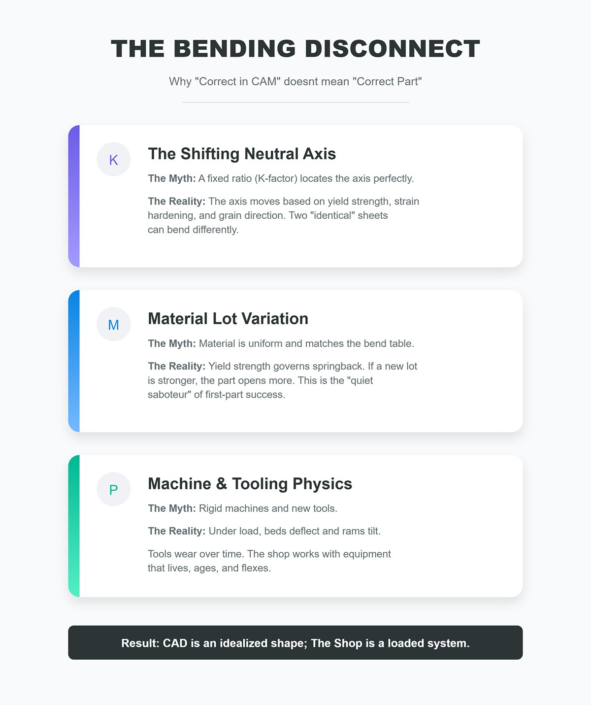
The neutral axis is not fixed. CAD systems rely on a K‑factor—a ratio used to locate the neutral axis within the material thickness—to calculate flat length. In practice, the neutral axis shifts with yield strength, strain hardening, grain direction, and true material thickness. Two sheets both labeled “304 stainless, 1.5 mm” can bend differently enough to miss angle and flange length, even with identical tooling and programs.
Material lot variation is the quiet saboteur. Yield strength governs springback. If an incoming lot is stronger than the material used to build the bend table, the part will open more after unloading. The chart didn’t change—but the material did. Without validating material behavior by lot, first‑part success becomes luck rather than process control.
The machine and tooling are part of the geometry. Under load, press brake beds deflect, rams tilt by microns, and crowning systems work to compensate. Punch noses wear, die shoulders round over, and backgauges develop backlash. Each of these changes the effective tool geometry during the bend. Charts assume rigid, like‑new components; the shop works with equipment that lives and ages.
This is why parts that “match the unfold” still fail inspection. The chart defines an idealized shape. The shop produces the outcome of a loaded, imperfect system.
The belief that the final angle equals the punch angle plus the die angle ignores the dominant variable in bending: springback. The angle you see under load is not the angle the part retains after unloading.
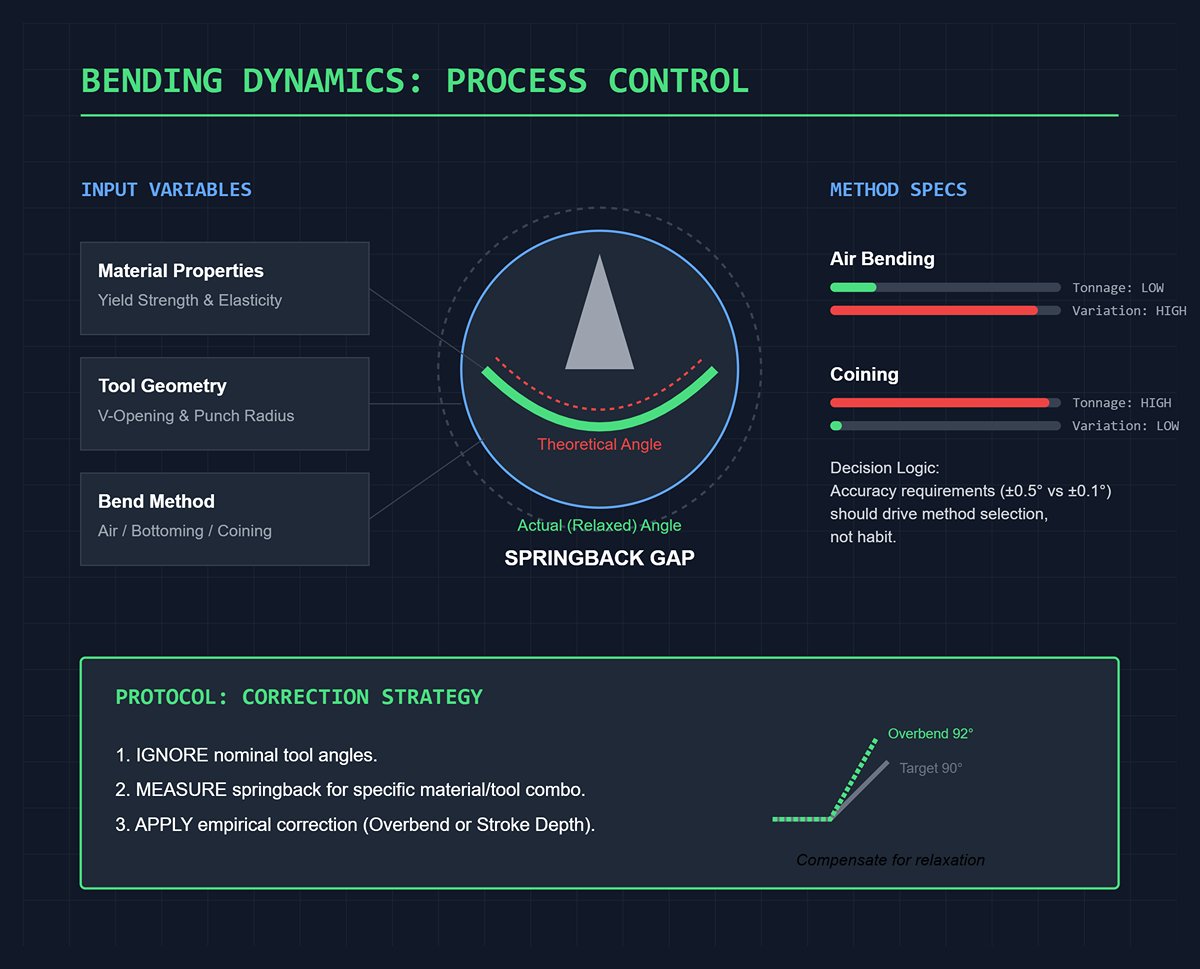
Springback is elastic recovery, not a mistake. When the punch retracts, the material releases stored elastic energy and relaxes, opening the bend. The amount of springback is driven by the strain imposed during forming, which in turn is governed by V‑opening width, punch nose radius, bend method (air bending, bottoming, or coining), and the material’s yield strength.
Tool angles are only a starting point. In air bending, the punch almost never fully contacts the die angle—the material rests on the die shoulders and wraps around the punch nose. Change the V‑opening or the punch radius and you alter the inside radius, the strain distribution, and therefore the springback. The nominal tool angles may be unchanged; the resulting bend will not be.
Bend method matters more than most charts admit. Air bending minimizes tonnage and speeds changeovers, but it also produces the widest springback variation. Bottoming constrains the part more tightly, reducing variability. Coining plastically deforms the material through its thickness, nearly eliminating springback—at the cost of dramatically higher tonnage and accelerated tool wear. Accuracy requirements (±0.5° versus ±0.1°) should drive method selection, not habit.
The practical takeaway is straightforward: you cannot program bend angles from tool geometry alone. Springback must be measured for the specific material, tooling, and machine combination, then compensated for with an empirical correction—whether via overbend or stroke depth—based on real data.
“Tweak it until it passes” feels fast. It is also expensive in ways most shops never bother to quantify.

Scrap compounds quietly. A 5% scrap rate on a 1,000‑piece run doesn’t just mean 50 bad parts. It consumes material, machine time, labor, and inspection capacity, while injecting uncertainty into delivery and quoting. The math is simple and unforgiving: scrap cost = piece cost × scrap rate × quantity. Run the numbers and the margin erosion becomes obvious.
Setup time is cheaper than rework. A 10–15 minute calibrated setup—using the actual material lot and the intended tooling—can eliminate dozens of trial hits. One short test bend, a measured angle, and a programmed overbend close the loop before production begins. That time is planned, predictable, and more than repaid through lower scrap and stable cycle times.
Repeatability beats heroics. Shops that invest in fast, disciplined calibration turn out first‑run parts that pass inspection, quote with confidence, and avoid constant firefighting. Shops that lean on tribal knowledge and “feel” simply move the cost downstream—to scrap bins, overtime, and customer concessions.
The promise here is straightforward: stop treating bend charts as gospel and start treating bending as a controllable process. Do that, and angles stop “mysteriously” drifting, setups shrink, and failures drop—not because the chart got better, but because your understanding did.
Air bending is the default in most shops because it’s flexible and requires relatively low tonnage. The sheet only contacts the punch tip and the two die shoulders; it never seats against the die sidewalls. That single fact explains everything that follows.
The die—not the punch—sets the outcome. Because the material is effectively “floating” in the V, the inside radius and final angle are governed by the die V‑opening and die angle, along with punch penetration depth. You can swap punch angles all day with minimal effect; change the V‑opening and the result shifts immediately. That’s why experienced operators tune angles through die selection and ram depth—not by chasing punch geometry.
Trade‑offs you accept: the lowest tonnage for a given thickness, quick setups, and the ability to run a wide range of angles with one toolset. In return, you live with the largest—and most variable—springback. Changes in material lot, grain direction, and machine deflection show up directly in the angle. Accuracy is achievable, but it’s empirical: measure, compensate, repeat.
Shop implications that matter: V‑opening width has an outsized effect on inside radius and springback (the familiar “~8× thickness” is a guideline, not a law). Smaller V’s tighten the radius and reduce springback—but drive tonnage up. Larger V’s reduce force but amplify variability. Crowning and ram parallelism matter here more than anywhere else.
Bottom bending drives the material firmly into the die angle under load. The punch continues until the flanges seat against the die faces, dramatically reducing springback compared with air bending.
Why shops choose it: When properly dialed in, bottom bending routinely achieves angular accuracy around ±0.5°. That’s not sales hype—it’s the natural result of forcing the part to fully seat into the die geometry rather than floating above it.
What you give up: higher tonnage than air bending and reduced flexibility. The die angle must match the target part angle (or be intentionally compensated), and the punch radius directly defines the inside radius. You lose the ability to casually run multiple angles from a single setup.
Where it shines: medium-volume runs with tight angular tolerances—especially when first‑part accuracy matters and you want to minimize trial bends. Springback still exists, but the correction window is narrower and far more predictable.
Setup realities: clearance must be correct to fully seat the flange without galling. Tool wear shows up as gradual angle drift—inspect and stone tooling before blaming the program. Bottom bending rewards disciplined tooling selection and maintenance.
Coining plastically deforms the entire bend zone to exactly match the punch and die profiles. Springback is essentially eliminated because the material yields through its full thickness.
What you gain: the highest level of repeatability and angle consistency available on a press brake. When variation is unacceptable, coining delivers.
What it costs: tonnage—often several times more than air bending the same material—and accelerated wear on tooling and machine components. Alignment, tool hardness, and surface condition become critical because contact stresses are extreme.
When it’s justified: short runs with zero tolerance for variation, or parts where springback must be eliminated entirely and the machine has ample capacity. Coining isn’t a shortcut for poor tooling decisions; it’s a conscious trade of force and wear for certainty.
A hard truth: adding tonnage to “fix” inconsistent bends only masks the real problems. Improper V‑opening selection, worn tooling, or uncrowned beds will resurface later—often as cracked tools or damaged machines.
One Technique to Try — Five Minutes to Better Angles
Goal: reduce angle chasing on air bends without changing tooling.
This simple calibration approach respects what air bending really is—an empirical process—and converts unavoidable variability into a controlled, repeatable input.
Choosing between air bending, bottom bending, and coining isn’t about right versus wrong. It’s about deliberately trading flexibility, tonnage, tooling wear, and repeatability to suit the print in front of you.
Most articles present the 8× rule as a prescription. It isn’t. It’s a triage tool—a quick way to get into the right neighborhood for mild steel air bending when little else is known.
The rule states that the V‑opening should be roughly eight times the material thickness. Shops favor it because it usually delivers reasonable tonnage, an acceptable inside radius, and predictable springback for low‑carbon steel. The hidden problem is that it quietly assumes average tensile strength, average ductility, and flange lengths that are well within die limits. Change any one of those, and the rule starts to fall apart.
A more effective way to use 8×T is as an initial checkpoint followed by three immediate questions. First: does the print require an inside radius smaller than that V will naturally produce? If so, the V must be reduced—or the forming method must change. Second: is the material high‑tensile, prone to work hardening, or sensitive to cracking? If yes, the V should usually be increased to lower tonnage and surface strain. Third: are the flanges short relative to the die width? Short flanges sharply concentrate tonnage and can exceed die ratings even when total machine tonnage appears safe.
This is why experienced shops rarely rely on a single universal multiplier. They think in ranges. Thin mild steel may live comfortably at 8×. Thicker gauges often drift to 9–10×. Stainless steels and high‑strength alloys commonly end up at 10–12× or more. The “rule” still exists—but only as the first step in a decision tree, not the decision itself.
In air bending, the inside radius is not stamped in by the punch. It is created by material flow between the punch tip and the die shoulders. The V‑opening is the primary driver of that flow.
In practical terms, a larger V‑opening yields a larger inside radius and requires less tonnage. A smaller V tightens the radius but demands more force and increases surface strain. This is why changing only the die can often correct a radius issue without touching ram depth.
For standard 90° air bending, many shops find the resulting inside radius falls roughly between 0.02×V and 0.08×V, depending on material and punch tip radius. That range matters. It means two dies that both satisfy the familiar “8× thickness” guideline can still produce noticeably different radii—and therefore different springback—on the same part.
This is where static charts fall short and quick empirical tests pay off. Bend a coupon in the chosen V, measure the inside radius, and log it for that material batch. One test turns a rule of thumb into a known result. Over time, those notes become more valuable than any generalized chart.
The most persistent misconception is that the punch tip radius equals the inside radius. It doesn’t—except on rare occasions by coincidence.
The inside radius is the combined outcome of three factors: punch tip radius, V‑opening, and material behavior. When these are out of balance, angle control suffers—even if the tonnage is technically correct.
A punch that is too sharp relative to the V‑opening and the material’s ductility can force an unintendedly tight radius, increasing springback variability and the risk of cracking—especially in high‑strength steels. A punch that is too blunt, on the other hand, can prevent the material from fully seating in the die during air bending, leading to under‑bent angles that chase ram depth without ever stabilizing.
A dependable shop guideline is to start with a punch tip radius of about half the material thickness for most mild and stainless steels in air bending. That geometry tends to work well with common V‑openings and produces stable, repeatable angles. Softer materials like aluminum often benefit from a larger punch radius—closer to the desired inside radius—to reduce thinning and surface marking.
The quickest way to see the effect is through a controlled comparison. Bend the same coupon in the same V at the same ram depth, change only the punch radius, then measure the inside radius and final angle. The difference is rarely subtle—and once you see it, the “punch equals radius” myth is hard to unlearn.
Thick sections and high‑tensile alloys are where simple rules turn risky.
As thickness and strength increase, required tonnage climbs fast. Forcing an 8× V on heavy or hard material often compresses the safety window: cracked parts, unpredictable springback, or overstressed tooling. In these cases, opening up the die—often to 10–12× thickness or more—isn’t laziness; it’s risk management.
If the print calls for a tight inside radius on thick or high‑strength material, air bending may simply be the wrong process. Bottom bending or coining concentrates deformation and locks in the radius, but at the cost of much higher force and dedicated tooling. Trying to “cheat” a tight radius in air bending by shrinking the V is how dies get damaged and angles start to wander.
Die capacity matters just as much as machine tonnage. Short flanges in thick material can concentrate load beyond a die’s rating even when the press brake itself is capable. Many tooling failures don’t happen because the rule was unknown—but because die ratings were never checked against flange length and the selected V.
When none of the ideal options fit, the right answer is often upstream: accept a larger radius, redesign the flange, or change the material condition. Tooling choices can solve many problems—but not physics.
Most discussions of V‑die selection miss a key point: they assume calculation replaces observation. In practice, the most reliable shops formalize a short, on‑machine test and treat it as part of setup—not troubleshooting.
Cut a small coupon from the actual material batch. Bend it centered in the chosen V using the intended punch at nominal ram depth. Measure the angle, inside radius, and springback. If the result is off, change one variable at a time—V‑opening first, then punch radius, then method—and repeat. Two or three bends usually converge on a stable solution.
That ten‑minute routine accomplishes what no rule can: it maps real material behavior to your tooling and machine. The 8× rule gets you close. The test makes it right.
Most flat patterns fail before they ever reach the press brake. Not because the brake can’t hit angle, but because the laser is asked to cut a fiction: one bend deduction applied to bends that behave nothing alike.
On the shop floor, every bend is a local event. Change the die opening to clear a return flange, tighten the inside radius to control springback, or switch from air bending to bottoming on a single hit—and that bend’s deduction stops being interchangeable. Drawings and nests often assume otherwise. The result is death by millimeters: 1–2 mm of error per bend compounds into misaligned flanges, drifting slotted holes, and laser operators forced to re‑nest parts mid‑run.
Consider a simple two‑bend part in 3 mm mild steel. One bend forms over a tight V for clearance; the second uses a wider die to avoid marking. The inside radii differ, so the bend deductions must differ—BD1 and BD2. Assume they’re equal and a nominal 90 mm + 65 mm flange collapses into an 84.5 mm flat that’s 1.2 mm short. The mistake doesn’t reveal itself at the brake; it shows up at the laser, where 20% more sheet gets scrapped because the nest no longer fits.
Laser operators don’t hate math—they hate averaged math. The fix is procedural: subtract half the bend deduction from each flange leg, subtract the full deduction from any shared base, and calculate every bend on its own terms. A 6‑inch base with two bends doesn’t “lose” one BD; it loses two half‑BDs. Miss that, and the blank is wrong before the first cut.
The neutral axis is not the center of the sheet. It’s the line through the thickness where the material neither stretches on the outside nor compresses on the inside during bending. Its position governs bend allowance (BA) and, by extension, bend deduction (BD). Get it wrong, and no amount of angle correction will save your flat.
In air bending, the neutral axis typically falls between 0.33T and 0.5T from the inside face, expressed as the K‑factor. Sharp bends pull it inward; larger inside radii push it outward. Material strength and grain direction matter just as much. Higher‑yield steels can shift the neutral axis outward by 10–15%, elongating the outer fibers more than mild steel under the same tooling.
The math leaves no room for mercy. For a 90° bend, the bend allowance is BA = A(π/180)(R + K·T). Take 2 mm 1018 steel with a 2 mm inside radius and K = 0.40: BA comes out to 3.53 mm. Miss K by just 0.1, and a 100 mm leg unfolds to nearly 101.8 mm. That’s not a rounding issue—it’s a systematic mismatch that shows up part after part.
Most shops rely on software defaults that are wrong by design. CAD/CAM systems have no visibility into your actual material lot, grain direction, or how aggressively you’re air bending. A five‑minute shop test will outperform any database. Bend a marked test strip, section it, and measure where the unstretched line sits relative to the inside face. Divide that distance by the thickness—that’s your true K‑factor. Even without etching, comparing post‑bend leg growth to calculated values will pin K within ±0.02. That small correction eliminates most “mystery” flat errors in mixed‑material production.
Defaults are averages. Production demands specifics. A K‑factor of 0.42 might be broadly “acceptable” for mild steel, yet it’s just as often wrong when mills, thickness, or forming methods change. The cost doesn’t show up as a software warning—it shows up as first‑part scrap and laser rework.
Deriving your own K‑factor is a single‑bend exercise. Cut a rectangular blank, program a known angle with known tooling, and measure the actual flat leg lengths after bending. Solve for K using the bend‑allowance equation with real dimensions, not nominal mold lines. Repeat the test whenever you change material, thickness range, or bending method. Air bending, bottoming, and coining do not share K‑factors; coining, in particular, can reduce bend deduction by roughly 20% due to through‑thickness compression.
Empirical data backs this up. Mild 1018 steel typically runs around K = 0.40 in air bending, dropping to about 0.35 when bottomed and 0.30 when coined. Stainless steels push higher—often near 0.45 in air bends—with greater springback that demands additional angle compensation. High‑strength HRPO can exceed 0.48, which explains why generic tables miss by half a millimeter on 6 mm stock.
The unexpected twist: most articles treat the K‑factor as a material property. It isn’t. It’s a process signature—the combined result of material, tooling, and method. When shops test and lock in K by lot and process, bend deductions stop being tribal knowledge and become standards. One fabricator cut first‑part scrap from 15% to 2% simply by deriving K before nesting and feeding those values back into CNC programs. The laser stayed the same. The blanks didn’t.
Most press brake failures aren’t caused by bad calculations. They happen because shops assume averaged tonnage applies uniformly along the entire bend. It doesn’t. Tonnage is local, method‑dependent, and brutally unforgiving when it concentrates. This is the line where shops either protect their equipment—or quietly shave years off its service life.
Strip away the theory and the air‑bend tonnage rule is straightforward: force increases with the square of material thickness and decreases as the V‑opening gets wider. Everything else is just a modifier.
A practical, shop‑grade version of the air‑bend formula looks like this:
Required tonnage ∝ (material factor) × thickness² × bend length ÷ V‑opening
That’s why doubling thickness doesn’t merely double the force—it quadruples it. And it’s why opening up the die is the fastest way to reduce tonnage without changing the part geometry.
Use mild steel as your baseline. As tensile strength rises, multiply accordingly. Stainless and high‑strength steels drive tonnage up quickly; aluminum pulls it down. The math doesn’t need to be perfect to protect the machine—it needs to be honest about scale.
Method choice multiplies everything. Air bending is the baseline. Bottoming typically requires three to five times the air‑bend tonnage. Coining can demand eight to ten times more. Switching from air bending to bottoming to “fix” angle consistency—without rechecking tonnage—is one of the fastest ways to overload a press brake.
A practical production rule is to maintain at least a 20% capacity margin above calculated tonnage. If a job only runs safely at the machine’s limit, it isn’t safe—it’s just temporarily successful.
Quick example: A 1 m bend in 4 mm mild steel using a V‑opening around ten times material thickness is well within air‑bending limits. Switch that same setup to bottoming and the tonnage jumps by several multiples. Coin it, and the required force can exceed the machine rating—even though nothing about the part looks heavier. The material didn’t change. The method did.
Here’s the failure mode most articles overlook: sinking tonnage. It occurs when a short or narrow flange concentrates force into a very small contact area, driving local loads beyond what the frame or tooling can tolerate—even when the calculated tonnage for the overall bend appears perfectly safe.
Most tonnage calculators assume the load is spread over a reasonably long bend. They compute force per unit length and then multiply by the full bend length. That logic breaks down when the effective contact length is short—tabs, narrow legs, small return flanges, or partial bends that never engage the full die width.
The machine doesn’t experience “average tonnage.” It feels force only where the punch actually touches the material.
To catch the trap before it snaps shut, run two simple checks:
If that localized force starts to approach tooling ratings or the machine’s per‑point limit, you’re already in the danger zone—even if the total tonnage number still looks acceptable.
The fixes are mechanical, not mathematical. Open the V‑die to reduce force. Switch from bottoming back to air bending. Add support or backup tooling to spread the load. Or split the operation so no single hit concentrates stress. What never works is ignoring the risk because the nameplate tonnage says you’re “within limits.”
Nameplate tonnage is not permission—it’s a headline. The fine print lives in the load‑limit curve.
Every press brake includes a curve that shows allowable tonnage versus V‑opening or bending length. It exists because frame stress is not linear. Narrow dies, short bends, or off‑center loading all reduce what the machine can safely handle—even when total tonnage stays below the rated maximum.
Two mistakes lead to costly damage. First, assuming the rated capacity applies to every setup. Most ratings assume full‑length, evenly distributed loading with a specific V‑opening; change the setup and the allowable tonnage drops. Second, focusing only on frame capacity. Tooling, clamping systems, and punch holders often fail long before the frame does.
If your calculated tonnage just grazes the top of the load curve for the chosen V‑opening, that’s not a green light—it’s a warning. Increase the V, split the bend, or change the forming method. More horsepower won’t save a frame from stresses it was never designed to absorb.
Tooling limits matter just as much. Dies are rated for maximum tonnage per unit length; exceed it and the die can permanently spread or crack. Punches with small nose radii intensify stress, and under high tonnage they deform or chip. Minimum punch‑radius guidelines exist for a reason—follow the manufacturer’s limits, not your gut.
The unexpected turn: Most shops assume tonnage problems announce themselves with alarms, fault codes, or a stalled ram. In reality, the damage is incremental and silent—subtle frame stretch, dies slowly opening up, punches losing their edge. By the time accuracy starts to wander, the machine has already paid the price. Understanding tonnage limits isn’t about getting today’s bend to form; it’s about running the next ten thousand parts without regret.
If tonnage determines whether the machine survives, material reality determines whether the part is right. Yield strength is the threshold where steel stops behaving elastically and begins to hold a permanent bend—and that threshold is not a constant. Mill test reports (MTRs) reveal what the steel actually is, not what the purchase order assumed it would be.
Cold‑rolled 1018 often certifies around 370 N/mm², yet real heats frequently test 10–20% higher due to rolling reduction and work hardening. That gap is more than academic—it’s enough to turn a “perfect” 90° air bend into an 88° part after springback. Operators blame the tooling. In reality, the steel was the variable.
Grain direction amplifies the effect. Sheet steel is rolled, elongating grains along the rolling direction. Bend parallel to that direction and those stretched grains resist compression unevenly, producing 15–25% more springback than a cross‑grain bend. Bend perpendicular to the grain and the structure collapses more uniformly, holding angle far more consistently.
This isn’t theory—it’s scrap arithmetic. Roughly three‑quarters of inconsistent bends can be traced to ignored mill certs and grain orientation. High‑tensile surprises are the worst offenders: a batch of DP980 sneaking into a “mild steel” job may require roughly 2.5× the overbend of A36 just to hit the same final angle.
Practical reality: Mark grain direction before the sheet ever reaches the brake. A quick file‑scratch across the surface will reveal it instantly. No cert on the pallet? Assume variability, plan for trial bends, and prove the setup before committing production.
Springback is simply elastic recovery. You drive the material past yield, release the load, and the metal relaxes open. The goal isn’t to eliminate springback—that’s unrealistic—but to predict it accurately enough that the finished angle lands exactly where it needs to be.
On the shop floor, springback is driven by three things: material strength, thickness, and inside bend radius. A handy rule of thumb is the springback factor (Ks). For mild steel in a typical air bend—around 2 mm thick with an inside radius roughly equal to the thickness—Ks usually falls between 1.05 and 1.20. Stainless and high‑strength steels climb quickly: 304 stainless commonly runs around 1.18, and advanced high‑strength steels can push past 1.25.
In practical terms, that means if you drive the punch to a nominal 90° stop on 304 stainless, you’ll often pull the part and read closer to 86°. There’s no mystery involved—just elastic recovery that wasn’t accounted for.
If you need a quick estimate without software, radius and thickness get you most of the way there. As the inside radius increases relative to material thickness, springback increases right along with it. For example, a 4 mm inside radius on 2 mm cold‑rolled steel will typically open up about 2° after release. It’s not a universal constant—but it’s close enough to dial in a smart first hit.
Hidden trap: springback is cumulative. A four‑bend box doesn’t magically average out small errors—it stacks them. Miss each bend by 2°, and by the time the last flange closes you’ve lost 8° of parallelism. That’s how parts with “in‑spec” single bends turn into scrap at the assembly stage.
Lot‑to‑lot variation is unavoidable. Even material from the same supplier can behave differently from heat to heat, shifting springback by 5–15%. The most reliable control is a witness strip: bend a 100 mm sample to the target angle, let it relax, measure the difference, then apply that correction across the run.
| Material | Thickness (mm) | Typical Ks (90° Air Bend) | Predicted Springback (°) |
|---|---|---|---|
| Mild Steel (A36) | 2 | 1.08 | 2.5–3 |
| Cold‑Rolled 1018 | 3 | 1.12 | 4–5 |
| 304 Stainless | 1.5 | 1.18 | 5–7 |
| DP980 High‑Strength | 2 | 1.25+ | 8–12 |
Overbending isn’t a workaround—it’s the core correction method. You deliberately bend past the target angle by the expected amount of springback, then let elastic recovery bring the part back to spec.
Aiming for 90° in mild steel with Ks ≈ 1.08? Drive the punch to about 87°. Release, measure, and you’re typically right on target. This hands‑on approach still outperforms default CNC compensation in most real‑world shops, because CNC assumes a stable K‑factor. In reality, K can swing from 0.28 to 0.42 depending on material certs, grain direction, and bend radius. Operators who validate with a test strip routinely cut scrap by 40% on mixed‑lot jobs.
With large bend radii and thin material—where springback can reach 15–20%—trying to hit the angle in one heavy stroke usually magnifies error. Incremental overbending is far more reliable. Approach the target in 1° steps over two or three hits; the material settles, and angle variation drops dramatically.
Coining can all but eliminate springback (Ks ≈ 1.00), but the cost is steep: up to ten times the required tonnage and significantly accelerated tool wear. Reserve it for ±0.2° tolerances where no other method will pass inspection.
5‑Step Overbend Routine (No Software Required):
Immediate win: Pull a single sheet from the current job, mark the grain direction, and run one witness bend before starting the next batch. When the first production part comes off dead‑on—no chasing the angle—the method proves itself in minutes. Not theory. Parts that fit.
The canoe effect is the classic long‑bend failure mode: the included angle is tightest in the middle and opens up toward both ends, giving the part a shallow, boat‑like profile. Most explanations get one thing wrong—they blame the material first. Material variability matters, but only after you understand the beam you’re bending on.
Under load, a press brake is not rigid. The ram elastically bows and the bed deflects, even on heavy machines. This deflection changes the punch‑to‑die clearance along the length of the tooling. During the hit, the ends experience a different effective gap than the center. When the load is released, springback doesn’t “average out”—it freezes those differences into the part.
A few thousandths of an inch of deflection doesn’t sound significant. On a long bend, it’s everything. Tiny clearance changes translate directly into angle error, often blowing past ±0.5° tolerance limits. Cranking up tonnage may mask the issue temporarily, but it increases stress on tooling and the machine, accelerates wear, and introduces new variables.
Secondary factors can magnify the problem: off‑center part loading, loose or mismatched tooling, uneven hydraulic response between cylinders, or variations in material properties across the sheet. Still, the underlying physics doesn’t change—elastic deflection under load followed by springback after release.
Quick diagnostic: Bend a full‑length test piece and measure the angle at both ends and at the center. Then flip the blank end‑for‑end and repeat. If the error remains centered on the machine, deflection is the culprit. If the error follows the sheet, material inconsistency is adding to the problem.
In practice, there are only two ways to counter elastic deflection: passively force the tooling back into parallel, or actively reshape the machine while it’s under load.
Shimming and manual alignment are the lowest‑cost approach. Thin shims placed under the die—most often near the ends—reduce the effective gap where the machine opens under load. When done carefully, this can straighten angles along the length for short runs or occasional long parts. A straightedge and a test bend indicate when you’re close; just a few thousandths of shim can make a meaningful difference.
Shimming works best with moderate tonnage, limited part variety, and stable setups. Its limitations appear quickly: time‑consuming iteration, sensitivity to material variation, and the reality that every change in thickness or bend length requires a new shimming strategy.
Active crowning addresses the same issue in a controlled, repeatable way. Mechanical crowning uses cams or adjustable supports in the die rail to introduce a preset crown. Hydraulic crowning applies adjustable pressure points beneath the bed or above the ram. CNC crowning integrates this adjustment into the control, calculating the required compensation for each program.
The objective isn’t to make the machine straight when unloaded, but straight under bending load. When properly calibrated, active crowning produces a uniform effective closure across the entire tooling length, independent of tonnage distribution.
The payoff is consistency. Long parts, tight angle tolerances, mixed material thicknesses, and high‑variety production all favor active crowning. The trade‑offs are upfront cost and the need for disciplined calibration—but the gains in reduced scrap, faster setups, and less operator guesswork usually outweigh them.
Decision rule: If the downtime spent iterating shims costs more than a crowning system over its service life, the choice is already clear.
Most discussions of canoeing overlook the backgauge—and that omission is expensive. Uneven bend angles are frequently amplified by uneven loading.
The backgauge determines where the part contacts the tooling and how square it sits to the bend line. When a long or asymmetric blank is pressed harder against one gauge finger than another, the bending load shifts. That imbalance increases localized deflection, causing one end of the part to behave differently from the other—even with perfect crowning.
Treat the backgauge as a positioning and squareness system, not merely a stop. Multi‑axis gauging lets you support long flanges evenly and keep the bend line perpendicular to the tooling. For large parts, auxiliary supports—such as rollers or side arms—prevent sag that would otherwise distort force distribution during the hit.
Calibration matters. A backgauge that repeats accurately but isn’t square will simply repeat the same mistake. Minor perpendicularity errors at the gauge quickly show up as visible angle differences at the ends of long bends.
What most articles get wrong: they chase angle uniformity with more tonnage instead of better information.
Run a controlled five‑step canoe test and let the machine tell you what it actually needs.
The surprise is how little correction is usually needed once deflection, compensation, and loading are properly aligned. When the canoe effect disappears, angle control stops being a guessing game and becomes a repeatable, documented setup.
The first part isn’t a formality—it’s the point where guessing ends and control begins. One clean bend, measured correctly, tells you whether you’re about to run good parts or produce consistent scrap. This checklist turns that single part into a decision point, not a hope.
If you’re still checking press‑brake angles with a protractor, you’re not truly measuring—you’re interpreting. Curved flanges, mill scale, and parallax force your eye to “average” a surface that isn’t flat. The result is predictable: shops routinely see 0.5–1° overestimation on 90° bends under 6 mm, and the error grows on high‑tensile steels where springback continues after the tooling opens.
A digital angle gauge changes the measurement from subjective to physical. With a magnetic base locked to the flange, it references gravity—not eyesight. Quality units resolve to 0.1° by averaging contact across the surface, which is why shop trials consistently show variance dropping from about ±1.2° with protractors to ±0.3° across ten parts on the same setup.
Action to take: On your next setup, bend a 100 mm test flange to nominal. Measure it once with a protractor, then again with a digital gauge after a 30‑second hold. If the readings differ by more than 0.5°, retire the protractor from first‑part inspection. Shops that make this switch typically reduce angle‑related scrap by about 40% on ±0.5° tolerance work.
Remember this image: the protractor reports what your eye wants to believe; the digital gauge reports what the steel actually did.
Angle alone doesn’t define a good part. Flange length is where many “approved” first parts quietly fail later, and the mistake almost always starts with measuring the wrong side.
Inside measurements—from bend tangent to edge—mask radius growth. In air bending, the neutral axis shifts as the radius forms, often ending up 10–20% larger than charts predict. On a 2 mm steel part bent in a 16 mm V‑die, that hidden growth can make the inside flange appear perfect while the outside dimension is already 1–2 mm short.
Outside measurement—flange height from the part base—reveals the truth. It captures the combined effects of angle, radius, and bend deduction. Rework logs tell the same story over and over: inside dimensions pass, assemblies fail. In more than half of these cases, the root cause isn’t the backgauge—it’s a punch or die radius that doesn’t match the material.
The discipline that pays: On the first part, measure both sides. Use calipers for the inside if needed, but use a depth micrometer or height gauge on the outside to avoid jaw slip on oily flanges. Outside checks catch roughly 80% more tooling and bend‑deduction errors than inside measurements alone.
If the inside dimension looks good but the outside flange comes up short, don’t start chasing the backgauge. That symptom points to springback or a radius mismatch—not a positioning error.
This is where most setups derail—not because the solution is a mystery, but because the wrong control gets adjusted.
Use ram depth for angle-only corrections. In air bending mild steel under 4 mm, a 0.1 mm change in depth shifts the angle by roughly 0.5°. That makes depth ideal for dialing out springback after the first angle check. If you’re within ±1° on angle and flange lengths are within ±0.2 mm, depth is the right lever.
Change tooling when dimensions or material behavior are fundamentally wrong. Flange variation greater than 0.3 mm, cracking, or a visibly pinched radius are not depth issues. A V‑die narrower than about 6× material thickness concentrates load and drives center overbend. A punch radius larger than half the material thickness promotes cracking on the outside fiber. No amount of ram tweaking will fix that—it only conceals the problem until inspection.
Burn this sequence into muscle memory:
Keep this cautionary image in mind: perfect angles on cracked parts. Ram depth can hide bad tooling until an entire run fails.
The operator at the start of this article was battling a long bend that “never matched the drawing.” The fix wasn’t more tonnage or endless tweaks—it was a disciplined first‑part inspection that revealed the truth. Measure the angle correctly, verify the flange where it matters, and pull the right lever. Do that, and the first part stops being a guess and becomes a verdict.


