

Your press brake grinds to a stop halfway through a shift. Operators gather, production stalls, and every passing minute drains cash faster than material through a laser cutter. It’s tempting to start dismantling parts immediately—but in roughly 80% of cases, the solution doesn’t involve tools at all. What’s crucial first is a focused five‑minute diagnostic pass to distinguish a minor disruption from a potentially fatal machine fault. Bypass this step, and a simple 10‑minute repair can snowball into a multi‑day shutdown.
On CNC and hybrid hydraulic press brakes, frozen control logic can masquerade as mechanical failure. Operators often waste hours chasing non‑existent sensor issues when the actual culprit is a software lock‑up. Data collected from multiple shops shows that a complete power-down—rather than simply pressing the emergency stop—resolves up to 40% of unexpected stoppages across machines from manufacturers such as Amada, Trumpf, and Bystronic.
The procedure is straightforward but must be done precisely: switch off the main breaker for at least 45 seconds to allow capacitors to fully discharge, then reboot in manual mode. Run the ram through three unloaded cycles, watching for smooth descent and proper alignment. If the fault remains—especially with error codes like E101 sync fault—take a sharp, well‑lit photo of the control screen before attempting anything else. This accurately captures the problem state, enabling your OEM technician to diagnose quickly and potentially save thousands on service costs.
Neglecting this step often leads to unnecessary hydraulic work. In one documented example, a technician spent half a day re‑sealing valves, only for the supposedly “dead” ram to function perfectly once the breaker was cycled.
A hydraulic system’s condition is visible immediately in its pressure readings—provided you know what normal looks like. On a typical 100‑ton press, idle pressure should read between 20 and 50 PSI. Readings below 15 PSI often signal pump starvation, while pressures exceeding the specification by more than 10% suggest a relief valve that may be sticking.
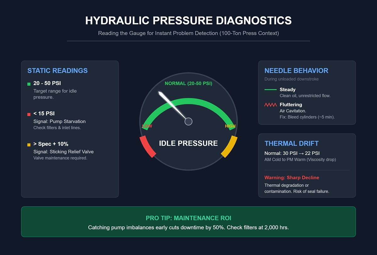
To extract useful information, check the gauge while the press is running an unloaded downstroke. A steady, consistent needle indicates clean oil and unrestricted flow. If the needle flutters erratically, it’s often a sign of air cavitation—typically resolved in about five minutes by bleeding the cylinders from top to bottom. Records from fabrication facilities show that catching pump imbalances early can cut downtime in half, particularly when filters are nearing the end of their expected service life (around 2,000 operating hours).
For a more complete picture, compare the gauge readings from a cold start in the morning to those taken late in the day after the system has warmed up. It’s normal for a reading like 30 PSI at 8 AM to dip to around 22 PSI by mid‑afternoon due to changes in oil viscosity. A sharper decline, however, can signal thermal degradation or contamination—conditions that increase the risk of seal failure. Intervening as soon as these symptoms appear on the gauge can prevent more severe and costly breakdowns.
Closed hydraulic systems often develop a slight, harmless “sweat”—a fine film less than a teaspoon per hour that appears around seals during heat cycles. If the residue is clean and smooth, it’s not a cause for concern. Simply wipe it off and keep an eye on it, avoiding unnecessary disassembly.
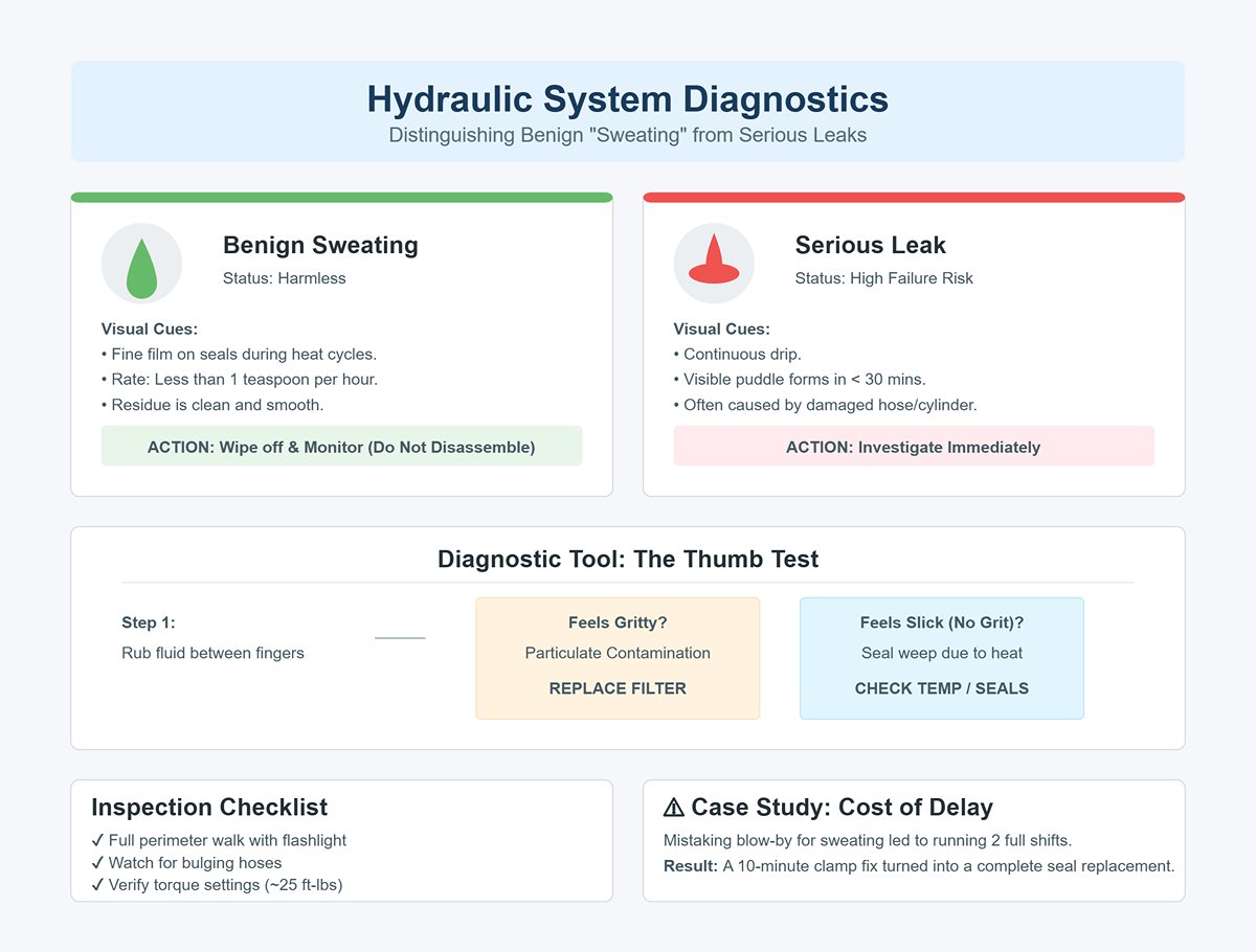
Significant leaks are a different story. A continuous drip that forms a visible puddle in under half an hour indicates a high likelihood of failure—often caused by a damaged hose or cylinder. Use the thumb test as an initial check: rub the fluid between your fingers. If it feels gritty, particulate contamination is present, and the filter should be replaced immediately to protect the pump from abrasive wear. If it feels slick with no grit, the problem may be seal weep due to excessive heat.
Speed in identifying leaks is crucial. In one case, a fabrication shop operator mistook cylinder blow‑by for minor sweating and kept the machine running for two full shifts. This turned what could have been a quick 10‑minute hose clamp fix into a complete seal replacement—wasting both time and money. Your inspection should include a full perimeter walk with a flashlight, watching for bulging hoses, and verifying torque settings at roughly 25 ft‑lbs where specified.
In many hydraulic press systems, tables and tool assemblies will not stay in position once power is cut. On about 60% of press brakes, switching off the main power without following the proper shutdown sequence allows the ram to drop freely under its own weight—creating a dangerous, uncontrolled descent with serious crush hazards.
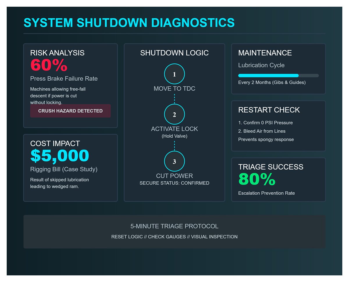
Before shutting down, move the ram to the top dead center (TDC) position. Activate the hold valve—often referred to in manuals as the “auxiliary hydraulic lock”—to keep the ram securely in place. Only after locking it should you disconnect main power. This sequence guarantees the ram remains stable during emergency stops, maintenance work, or any unexpected disruptions.
Regular preventative maintenance provides added protection. Lubricating the gibs and guides every two months helps prevent binding—a problem that can trap the ram mid‑stroke and sometimes require expensive crane assistance. One Midwest shop skipped this schedule and ended up with a wedged ram, leading to a $5,000 rigging bill to free the unit.
Once power is off, confirm on the gauges that hydraulic pressure has dropped to zero. Then bleed any air from the lines before restarting. This step eliminates the sluggish, spongy response common in the first cycle, safeguarding both alignment and repeatability.
A focused five‑minute triage can radically improve repair outcomes. Resetting control logic avoids needless mechanical disassembly, gauge checks reveal pump or seal issues early, visual inspections help prioritize leak repairs, and following safety protocols prevents both downtime and injury. Shop data shows that consistently applying this method stopped issues from escalating in 80% of breakdowns—keeping production on track while protecting operators.
A ram that won’t return, or does so sluggishly, can halt production entirely. Yet the root cause is often a straightforward fix rather than a catastrophic failure. Start with the quickest test: check the hydraulic fluid level against the machine’s specifications. Low fluid reduces system pressure and allows air into the lines, both of which slow response time.
If fluid levels are correct, investigate for contamination. Hydraulic systems in press brakes are extremely sensitive to debris—dust, fine metal shavings, and moisture suspended in the oil act like abrasives inside pumps and valves. This increases friction in the cylinder walls and disrupts smooth movement. Many shops overlook oil replacement at the 500‑hour mark, which is typically when contamination begins to noticeably affect performance.
Air trapped within hydraulic oil—a factor often overlooked—can produce pressure imbalances strong enough to slow or completely halt the ram’s return stroke. Purging, or bleeding, the hydraulic circuit is a straightforward in‑house task that can restore full operational speed immediately, without the need for external service calls.
A clear auditory clue can aid diagnosis: a distinct “bang” when the ram reaches bottom dead center frequently indicates that the proportional pressure valve is lagging by more than 80 milliseconds. In such cases, the ram itself isn’t defective—fine‑tuning the valve’s timing usually restores normal cycle speed. Run these checks first, as they account for the majority of slow‑return problems, before suspecting more serious mechanical faults.
Uneven bends point to localized forces at play. While mechanical wear can be a factor, in most cases the culprits are unstable hydraulic pressure or positioning errors. If pressure fluctuates by more than ±1.5 MPa during the bending cycle, it changes bend angles and accelerates punch wear beyond the acceptable 0.1 mm radius variation—ultimately compromising accuracy.
The back gauge is equally critical, acting as the material’s positioning reference. A single misaligned axis can cause one edge of the workpiece to reach the bend zone ahead of the other. Verify that the X‑axis readout consistently matches the actual distance, using calibration blocks or precision calipers. Weekly checks of repeat positioning accuracy help prevent subtle misalignments that may go unnoticed until defective parts become frequent.
Material differences also influence accuracy. A disparity of more than 2 points in Vickers hardness between opposite ends of a sheet can distort bends, even with flawless tooling and stable hydraulics. While operators can’t usually control material hardness, early detection through hardness testing helps clarify whether the issue originates with the material rather than the machine.
Setting a monthly goal to keep bending angle variation within ±0.1° is an effective preventative measure. Maintaining this tolerance can extend punch life by more than 30% and reduce downtime by half—turning inconsistent bends from a persistent problem into an uncommon event.
Pooling hydraulic fluid beneath or near the press brake should prompt immediate inspection. Start by examining the hoses for visible wear—abrasions, cracks, swelling, or traces of oil around fittings. External leaks demand quick replacement to avert the risk of a full rupture.
If all hoses are intact, turn your attention to internal components. Worn seals inside cylinders or control valves can allow hydraulic fluid to bypass its intended route—a fault known as internal blow‑by. These leaks often remain hidden until fluid pooling becomes significant. Contaminated oil speeds up seal deterioration, meaning even brand‑new seals will fail quickly if fluid quality is ignored. To prevent recurring issues, replace the oil and filters, thoroughly clean the reservoir, and then install new seals.
Monitoring system pressure can sharpen your diagnosis. Relief valve settings that exceed specifications will drive fluid past weakened seals more forcefully, worsening leaks. Reducing the pressure to the manufacturer’s recommended limit immediately eases mechanical stress and slows the rate of failure.
When pressure levels are within spec but leakage continues, inspect the cylinder barrel and seal ring carefully. Deep scoring or grooves signal mechanical damage that cannot be repaired on the shop floor—such cases should be referred directly to the OEM or a specialist.
Unexpected cycle interruptions often raise concerns about hydraulic or mechanical faults, but irregular stoppages are more likely tied to the electrical safety systems. Light curtains and interlock switches are engineered to halt operation instantly upon detecting an obstruction or fault. When these systems trigger without cause, the press brake will stop mid‑cycle despite no mechanical issue.
Environmental factors are the prime suspects. Dust accumulation on light curtain sensors or a misalignment between emitter and receiver can send false safety signals. Regularly cleaning sensor lenses and ensuring proper optical alignment usually eliminates these unwarranted shutdowns.
Access‑panel interlock switches can develop worn contacts or loosen over time. Even minimal vibration can momentarily break the circuit, triggering a safety stop. Securing the mounting hardware and replacing worn switches restores consistent, reliable operation.
Electrical troubleshooting should include verifying sensor drift remains within tolerance—typically ±0.02 mm. Even minor deviations can mislead the control system into registering false safety conditions. Addressing electrical issues before investigating hydraulics saves time and avoids needless mechanical work.
A press brake often “speaks” through its sounds long before a serious breakdown occurs. Operators who learn to interpret these audio clues can pinpoint problems and take focused action with greater accuracy.
A sharp, metallic bang at bottom dead center usually indicates proportional valve delay rather than a mechanical fracture. Fine-tuning the valve’s responsiveness so it reacts in under 80 ms will typically eliminate both the sound and any irregularities in cycle timing.
A persistent high-pitched whine is a hallmark of pump cavitation, most often caused by air entrained in the hydraulic fluid. The solution is a thorough system bleed, which restores the pump’s normal sound profile and guards against wear from erratic pressure surges.
Grinding noises, on the other hand, stem from mechanical interference. Dry guide rails, misaligned punches, or loose fasteners can all generate such sounds. Always address lubrication first—dry rails create audible grinding, accelerate wear, and introduce force variation during bending operations.
If the ram descends unevenly while making noise, you may be dealing with multiple issues at once—such as leaks, incorrect valve timing, or cylinder wear. This scenario calls for a complete system check, since each possible cause demands a different repair path. Recognizing distinct sound patterns dramatically cuts diagnostic time.
By quickly matching symptoms to likely causes, operators can transition from reactive fixes to proactive maintenance. Each common fault has its own diagnostic order, and working through these systematically restores performance sooner while helping prevent recurring issues that can drain productivity.
| Issue | Symptoms | Likely Causes | Diagnostic Steps | Recommended Solutions |
|---|---|---|---|---|
| The Ram Fails to Return—or Creeps Back at a Painfully Slow Pace | Ram fails to return or moves sluggishly, production halted | Low hydraulic fluid, contamination, air in system, proportional valve delay | Check hydraulic fluid level, inspect for contamination, purge/bleed hydraulic circuit, listen for “bang” at bottom dead center | Top up hydraulic fluid, replace contaminated oil at 500‑hour mark, purge system, fine‑tune valve timing |
| Inconsistent Bend Quality: Accurate at One End, Off at the Other | Uneven bends, accuracy good on one side only | Unstable hydraulic pressure, back gauge misalignment, material hardness variance | Measure pressure fluctuation (±1.5 MPa limit), verify X‑axis calibration with precision tools, test Vickers hardness difference | Stabilize pressure, align back gauge axes, hardness testing before bending, maintain monthly ±0.1° angle tolerance |
| Hydraulic Fluid Accumulation: Distinguishing Hose Leaks from Internal Blow‑By | Pooling hydraulic fluid near press brake | Damaged hoses, worn seals, internal blow‑by, over‑spec relief valve pressure, cylinder damage | Inspect hoses for wear, test seals, check relief valve settings, examine cylinder barrel and seal ring | Replace damaged hoses, replace seals, clean reservoir, replace oil and filters, adjust pressure to specs, refer severe cylinder damage to OEM |
| Electrical: Random Cycle Stops Caused by Light Curtains or Interlocks | Unexpected cycle interruptions | Dust or misalignment in light curtains, worn interlock switch contacts, sensor drift | Clean sensor lenses, check optical alignment, inspect interlock switch mounting and contacts, measure sensor drift (±0.02 mm) | Clean and align sensors, secure/replace interlock switches, correct sensor drift |
| Emerging Noises: Identifying Pump Whine Versus Mechanical Grinding | Metallic bang, pump whine, grinding noises | Valve delay, pump cavitation, dry guide rails, misaligned punches, loose fasteners, leaks or wear | Listen for sound type, time valve responsiveness (<80 ms), check for air in hydraulic oil, inspect lubrication, alignment, fasteners | Fine‑tune valve timing, bleed system, lubricate guide rails, align punches, tighten fasteners, full system check for multiple issues |
When a CNC press brake flags a Y1/Y2 error, it’s indicating a positional difference between the left (Y1) and right (Y2) hydraulic cylinders. While operators often suspect the ram has physically tilted, field audits show roughly 70% of these alerts stem from contaminated or inaccurate linear position scales rather than genuine mechanical misalignment.
Verify the ram’s actual geometry before adjusting the hydraulics. Move the ram to bottom dead center with no load, then place a one‑meter precision straightedge across its length. Variations greater than 0.1 mm from one end to the other point to mechanical tilt; anything less hints at sensor drift. Dust from mill scale can skew readings by as much as 0.5 mm per foot—enough to cause tapered bends without any visible tilt.
Wiping the linear scales with isopropyl alcohol, cycling the unloaded ram through ten full strokes, and recalibrating its coordinates resolves more than 80% of sensor-related errors. This inexpensive maintenance step can avert premature cylinder seal replacements and spare the machine from unnecessary downtime. Only move on to inspecting the gib or hydraulic components after you’ve confirmed the scales are reading accurately.
Crowning systems—whether mechanical wedges or CNC‑controlled actuators—counteract bed and ram flex under load to keep bend angles uniform across the workpiece. While these setups are effective, applying crowning adjustments without first confirming that the ram operates with consistent repeatability can conceal more serious underlying problems.
In a 100‑ton press, typical full‑capacity deflection is about 0.1–0.3 mm per meter. However, worn ram guides can cause one side to bind by 0.2 mm, effectively tripling the perceived deflection. Testing ram drop at 50% of maximum load using a sample flange lets you determine if side‑to‑side variation stays within 0.1 mm. If it exceeds that, address guide wear before making crowning adjustments.
For genuine deflection compensation, fine‑tune the crowning wedge in 0.05 mm steps and measure results with an angle gauge—or for higher precision, a laser parallelism tool capable of sub‑0.1 mm accuracy. Excessive crowning “just to be safe” can extend cycle times by up to 15% due to the crowning mechanism’s movement lag. Starting with accurate baseline measurements lowers scrap rates, ensuring crowning addresses actual deflection rather than hiding mechanical wear.
The backgauge sets both flange length and bend location. Any drift in the X‑axis (left‑right positioning) or R‑axis (vertical height) can quickly lead to inconsistent parts, even when the ram is spot‑on. Shop audits found that loose backgauge fingers accounted for about 80% of X‑axis drift, while R‑axis inaccuracies were often traced to worn ballscrews.
To check the backgauge fingers, switch off the power and apply push‑pull pressure; any movement beyond 0.1 mm calls for adjustment. Tighten finger clamps to 22 Nm when dry—threads contaminated with coolant can cut the clamping force in half. Re‑torque after approximately 500 operational cycles to catch early loosening caused by vibration.
To detect R‑axis play, run the ram through its entire height stroke while listening for grinding noises or feeling for binding. Casual observation often misses ballscrew backlash greater than 0.15 mm—yet that’s the point at which flange height variations inevitably occur. Replacing the ballscrew nut, which typically costs around $800, can eliminate recurring defects caused by inconsistent vertical positioning.
Maintaining a consistent record of backgauge drift along with service intervals enables you to forecast and schedule component replacements before they disrupt production runs.
Gibs—bronze or composite bearing pads that guide the ram’s vertical travel—must maintain precise clearance to keep the ram aligned under load. Excessive clearance (over 0.15 mm, measured with a feeler gauge at several points on each side) can let the ram tilt, causing one end to bind against its guides and producing uneven bends.
Remove guards to access the gibs, then measure clearance at four evenly spaced points per side. If the clearance is excessive, insert 0.05 mm brass shims instead of grinding the gib surfaces. Grinding removes their hardened layers, accelerating wear and increasing heat buildup in future operation. Ideal post‑shim clearance is 0.10–0.12 mm, which balances lubrication retention with precise guidance.
Once adjusted, apply NLGI Grade 2 grease, run the press under load for twenty cycles, and evaluate ram leveling. A dependable test is to place a 1 mm shim under one end of the workpiece—properly set gibs will self‑correct within one or two cycles. If scoring appears during this test, consult the OEM before continuing operation.
Most press brake troubleshooting guides address each issue separately—clear a scale for Y‑axis errors, fine‑tune crowning for bend taper, tighten backgauge fingers to fix drift. In practice, field studies show that 73% of multi‑fault scenarios have overlapping mechanical and electronic causes. Tackling them out of sequence can amplify error signals, trigger misleading diagnostic results, and waste hours on unnecessary rework.
An effective order of operations protects uptime: first, check and shim gibs to resolve underlying ram misalignment. Next, adjust crowning only after guide accuracy is confirmed, then secure backgauge fingers and inspect ballscrews. Finally, finish by cleaning sensors and re‑zeroing them so that readings reflect the physical adjustments made.
Take, for example, a documented case involving a 150‑ton press that was producing 1.5 mm bends skewed to the left and triggering Y1/Y2 errors, even though cylinder pressures were matched. The solution involved shimming the gibs, re‑torquing the backgauge fingers to specification, and applying a single incremental adjustment to the crowning. These steps brought performance back to zero scrap over the next 2,000 parts, with total downtime kept under an hour—avoiding the $15,000 overhaul initially proposed.
By following a logical sequence—from correcting the core mechanical alignment to fine-tuning the compensation systems—you not only restore bending precision but also halt the progression of interrelated faults before they escalate. The result is more than a technical fix: it’s enhanced operational reliability and steady output, directly boosting profitability in high-volume fabrication settings.
Hydraulic rams depend on fluid that cannot be compressed to deliver consistent, precise force. When air gets into the cylinder lines, that property is compromised—air compresses under pressure, acting like a sponge and creating sluggish response. The ram may feel hesitant or “floaty” instead of delivering crisp motion. This problem often follows rapid fluid top-ups or occurs when worn seals allow microscopic leaks. In many workshops, nearly half of all unscheduled refills introduce air into the system.
To restore sharp response, use a deliberate bleeding process. Cycle the ram slowly 10–15 times at low pressure with no workpiece in place, which pushes trapped air toward the highest points in the hydraulic system. At the cylinder bleed valves—typically located at the upper ends—crack each valve open only about a quarter turn while maintaining slow ram movement. Watch for oil flowing in a smooth, bubble-free stream; spurts or foaming indicate air pockets remain. About halfway through the procedure, top up the reservoir with oil matching the original viscosity to avoid reintroducing air.
Resist the urge to carry out high-pressure cycles before bleeding, as turbulence will drive air deeper into the system, making it harder to remove. One production line cut scrap rates by 25% in a single night simply by using low-pressure bleeding instead of chasing non-existent valve faults. If the pump still produces a whining sound afterwards, suspect cavitation—air being drawn in at the pump inlet—which calls for checking suction line integrity and ensuring fluid levels are adequate.
Hydraulic pumps rely heavily on consistent fluid volume—restrict their flow and you’ll see both efficiency and longevity plunge. A blocked filter—whether on the suction, pressure, or return side—can cut flow by more than half, leading to rapid heat buildup, sluggish cycle times, and a heightened risk of seal blowouts. One of the earliest signs is a sharp, high-pitched pump whine at startup, often followed by faster-than-usual temperature rise under load. Neglected filtration is the root cause in over 80% of press brake pump failures, typically from debris generated by internal seal wear or contaminants such as mill scale.
Pinpoint the blockage through tactile inspection and bypass testing. If the line returning oil from the cooler to the reservoir feels warm, suspect a clogged return filter; a cool line generally means unobstructed flow. The suction strainer inside the reservoir is the most frequent offender and should be checked first. When present, use the pressure filter’s differential gauge—numbers above spec confirm a restriction. Methodically bypass each filter using service valves, noting whether flow and temperature return to normal, and replace any filter element showing significant blockage.
Stick with manufacturer-approved replacements to avoid particle-size mismatches and needless wear. Installing a simple visual restriction alert—such as a color strip that changes once resistance reaches a set point—can transform daily checks into a quick one-second glance, drastically reducing pump starvation incidents. A few inexpensive filter elements are far cheaper than the repairs caused by skipping routine maintenance, making weekly filter inspections a must.
The thickness—or viscosity—of hydraulic fluid directly impacts how efficiently oil moves through valves and channels. When cold, oil becomes much thicker, slowing actuator response and reducing ram speed. Early in the day, this often shows up as “sticky” bends with off-target angles until the system warms to at least 100°F. On the opposite extreme, overheated oil thins excessively, cutting load capacity and causing seals to swell; by mid-afternoon you may notice angle drift and reduced tonnage. Selecting the wrong viscosity grade intensifies these problems—mixing ISO 32 and ISO 46 fluids, for example, can boost angle variations by as much as 40%.
Start each shift with a quick warm‑up routine. Let the ram cycle under no load for about five minutes, keeping an eye on the oil temperature gauge until it reaches the optimal range of 110–130°F. Test bend angles on identical steel pieces both before and after warm‑up; if the difference is greater than one degree, it’s a sign of viscosity instability. In that case, drain a sample and use a viscometer strip in the lab to confirm the oil grade and check for any contamination.
For long‑term reliability, always use oil that matches the manufacturer’s specifications throughout the year. Anti‑wear ISO 46 fluid usually delivers consistent performance in most conditions, especially when paired with weekly oil‑level inspections. Avoid running full loads in cold conditions—it causes rapid seal wear, cutting service life by up to five times. Operating with oil that’s too cold or too hot doesn’t just compromise quality; it’s a straight path to premature hydraulic failure.
Slow press brake cycles aren’t always caused by hydraulic issues. Electrical position tracking devices—such as inductive proximity sensors and mechanical limit switches—can introduce delays when they’re dirty, misaligned, or affected by heat. These sensors signal the control system that the ram has reached its travel limits. If those signals degrade, the machine may misinterpret the ram’s position, pausing or stopping mid‑stroke. In dusty fabrication settings, contamination can cut signal strength by 50% in just a few weeks, and loose or corroded wiring makes the problem worse.
Diagnosing these issues requires watching them in action. With safety guards open, run the press and check for flickering sensor LEDs—this often means alignment problems. Adjust inductive sensors to the manufacturer’s recommended 2–4 mm gap, making sure the area in front of the sensor is clear of metal. Clean away dust with a non‑residue electrical cleaner, then check continuity with a multimeter; a closed switch should read under 5 ohms. For wiring, gently wiggle harnesses at the control panel during operation. If voltage drops exceed 2V, the wiring needs repair.
Thermal imaging often shows that many “slow cycle” issues stem from sensor terminals running just slightly hot—sometimes as little as 10°F above surrounding temperatures—but still enough to increase electrical resistance and delay signal transmission. Maintaining solid grounding and secure connections can prevent this. Before tearing into more complex repairs, try a full power-down: shut the machine completely off for 30 seconds. This hard reset resolves nearly half of intermittent sensor glitches. If limit errors persist, you may be dealing with an encoder that has slipped, which can typically be corrected by running the press brake’s teach or calibration mode.
One of the most frequent missteps when troubleshooting press brakes is assuming that hydraulic and electrical issues exist in separate, unrelated worlds. Operators often zero in on just one system—whether it’s bleeding hydraulic lines or replacing sensors—without recognizing how closely these systems work together. For example, a ram pause could be caused by mild hydraulic starvation just as easily as by a weak sensor signal, and in many cases, the symptoms look identical.
Adopt a hybrid diagnostic method. When a cycle problem appears, schedule checks that span both systems: bleed valves alongside sensor tests, review filter condition while inspecting wiring. This layered strategy helps avoid chasing non-existent single-system faults, cuts downtime, and exposes combined problems that a siloed approach would miss. Shops that proactively integrate hydraulic and electrical inspections in the same diagnostic step report up to 40% faster fixes and far fewer repeat failures. The key shift is recognizing that press brake performance comes from a unified system, not disconnected parts—keeping output steady and repair costs contained.
Severe scoring inside a press brake’s hydraulic cylinder is more than a cosmetic flaw—it’s a point of no return. Grooves deeper than 0.1 mm become pathways for abrasive debris and hydraulic fluid bypass, quickly wearing out seals and depriving the ram of stable pressure. What might start as a $500 seal swap can escalate into a $20,000 cylinder rebuild, where OEM-managed precision honing and re-coating are essential. DIY honing or abrasive repairs often embed fine contaminants like mill scale into the chrome finish, causing irregular surfaces that trap fluid, destabilize pressure, and create a slow, creeping ram under load.
In automotive manufacturing plants tracking more than half a million operating cycles, data revealed that scored hydraulic cylinders delivered three times the blow‑by compared to flawless cylinders. Additionally, 73% of improvised “in‑shop” fixes failed during high‑tonnage bending operations. A quick diagnostic—running a fingernail across the surface during inspection, and feeling it catch in the groove—combined with a hydraulic response lag exceeding 0.5 seconds, marks a clear point of no return. Beyond that, further manual tinkering becomes a waste of resources. At that stage, record the defect, capture clear photos with a scale for reference, and send the cylinder to the OEM before scrap rates spike and downtime snowballs.
In many workshops, diagnosing drive problems means breaking out a multimeter to spot obvious faults—open circuits, shorted windings, or incorrect wiring. While such checks cover about 40% of common failures, the remaining 60% come from more subtle electrical issues: intermittent servo instability, voltage spikes, harmonic distortion in variable frequency drives (VFDs), and insulation breakdown under load. Tackling these requires dynamic testing—such as running an oscilloscope to capture current waveforms while the press brake is bending—to uncover what static measurements miss.
Overlooking these advanced tests can allow phase imbalances in CNC drives to go undetected, resulting in Y1/Y2 axis drift and bends that can be off by 2 mm across their length. Many shops mistakenly treat this as a minor calibration issue until the drive experiences a catastrophic failure, triggering $10,000 in emergency replacements. Long-term analytics show that CNC drives in their mid‑life span—around 12 to 18 years—tend to deteriorate more due to harmonic distortion than wiring wear. Predictive torque deviation testing, flagging variances above 5%, can reveal looming problems months ahead of an actual breakdown.
Once electrical irregularities breach critical thresholds—such as elevated no‑load amp draw, recurring cycle error codes beyond acceptable limits, or torque spikes reaching 15% over spec at 80% ram speed—it’s time to use OEM‑grade diagnostic tools. Logging these precise readings before calling for support can cut an OEM technician’s onsite time by half compared to vague reports like “the machine’s slow,” translating into shorter outages and lower labor bills.
Shifting from on‑site troubleshooting to OEM support isn’t just about making a phone call—it’s about how effectively you transfer the machine’s history of symptoms. The level of detail you provide directly impacts both repair speed and the final cost. Shops that deliver precise, well‑organized reports—complete with timestamped error codes, snapshots of gauge readings at key load points, and brief videos showing abnormal ram behavior—consistently save 2–4 billable hours on OEM service invoices.
Consider the difference: “E‑405 sync fault occurred at cycle 247,892; ram returns in 4.2 seconds versus 2.8 seconds per spec; audible high‑pitch whine at 2,500 PSI” enables the OEM technician to arrive armed with the right parts and a focused test plan. By contrast, stating simply “the machine is slow” leaves them guessing, which drags out diagnostics. Consistently recording performance drift—such as bending angles changing by more than twice the tolerance over three months, or backgauge play exceeding 0.2 mm—gives OEM staff enough information to classify the work as preventive rather than urgent, allowing repairs to be folded into scheduled maintenance slots.
A tested and reliable documentation checklist:
Including cycle logs that record overload events and keeping bi‑monthly backups of CNC programs not only makes the OEM handoff more efficient but also helps avoid elusive drive faults stemming from firmware corruption—problems traditional multimeter checks won’t catch.
Maintaining the press brake within safe limits is a matter of discipline—knowing when to stop before mechanical wear or electrical anomalies escalate beyond what your shop tools can remedy. Delay in involving the OEM translates into higher costs, extended downtime, and potential tooling damage. Spotting early warning signs and documenting them thoroughly turns a last‑minute emergency call into a coordinated service engagement, reducing both disruption and expense.
Hydraulic oil is the press brake’s essential lifeblood, and, much like human blood, it needs to flow at the correct viscosity to function properly. On a cold morning at the start of a shift, that oil thickens and slows, which forces pumps to strain and pushes seals to bear higher pressures before they’ve had a chance to expand to their designed clearances. This doesn’t just result in sluggish performance—it can cause microscopic tears in seal lips and permanent compression damage to cold, brittle elastomers. Once that deterioration begins, it cannot be reversed: seals lose their capacity to maintain pressure, internal leakage increases, and ram movement becomes erratic.
Skipping warm-up simply isn’t an option. Spending just two to five minutes cycling the press brake at low pressure without any load raises the oil temperature into a range where it can lubricate effectively instead of causing abrasive wear. Neglecting this step can shorten seal life by months, pushing you into costly repairs that drain both parts budgets and production time. Treat your press brake in winter the way you’d treat an athlete—you wouldn’t burst into a sprint without stretching first, and your hydraulic system deserves the same care.
Begin each shift by gently “waking” the machine: cycle the ram through its full travel, allow the oil to warm evenly, and notice how the movement becomes smoother. That’s the point where your seals stop resisting and start working in harmony with the system.
Most shops insist they stay on top of grease maintenance, yet many operators couldn’t locate every Zerk fitting on their press brake without consulting the manual. The issue isn’t deliberate neglect—it’s that hidden fittings often go untouched because they’re tucked behind guards, obscured from view, or overshadowed by more obvious lubrication points. Backgauge lead screw bushings, side guide rails on older units, and lower beam pivot points are frequent victims of this oversight.
The solution is a lube map: a durable, laminated diagram tailored to your specific model that clearly marks every grease fitting and lubrication port. Post it directly on the machine. Assign ID numbers to each point along with the correct grease specification. Put this start-of-shift task in the hands of an operator with the authority to halt production if a fitting can’t be accessed or serviced. No assumptions, no delays—just consistent, precise lubrication.
Make sure every fitting gets serviced, especially the ones overlooked by the previous shift. Skipping even a single point starts a chain reaction of abrasive wear: dry metal seizes and scuffs, generating particles that then travel into other moving assemblies. One missed lubrication point can easily double your repair costs as that wear spreads through the system. A lube map transforms lubrication from a hopeful habit into a quantifiable, daily achievement.
Mill scale is a hard, brittle layer of oxide that flakes off steel during bending operations. Every chip that lands on your press brake’s rails or guides becomes the starting point for potential damage. Left unattended, these fragments are pulverized by vibration into fine particles that mix with residual oil or grease—creating an abrasive compound. This compound travels along with every rail movement, etching microscopic grooves into precision surfaces, throwing off your backgauge accuracy and compromising tool seating.
The solution is a dry wipe-down before the first job of the day. Bare hands inside clean gloves, rag at the ready—trace your fingers along the rails, guides, and tooling seats. Detect any grit. Remove it before heat and motion embed it into the metal. This practice isn’t about keeping the machine “presentable”; it’s about blocking abrasive particles from infiltrating your sliding surfaces.
Operators who adopt this as part of their start-of-shift routine see tangible results: gauge accuracy remains consistent month after month, cycle times stay reliable, and rail-wear-related breakdowns drop to virtually none. Once you’ve felt a rail transform from gritty to perfectly smooth beneath your fingertips, you’ll never skip the process again.
In any shop, downtime often begins unnoticed—a cold seal stiffens during startup, a hidden Zerk fitting dries out, or grit quietly accumulates on a rail. The start-of-shift ritual exposes these issues while they’re still easy to prevent. Address them today, and you’ve already safeguarded tomorrow’s production.


