

A 5×10 sheet of 10-gauge stainless doesn’t “feel” heavy until you’re the one holding the tail end while 120 tons of ram force comes down.
I’ve watched grown men lean their body weight into a sagging sheet mid-cycle, boots sliding on concrete, trying to keep the bend line true while the press brake keeps moving like it doesn’t care. The part comes out with a subtle twist. Everyone blames timing. Or inexperience.
But what if the machine and the support were fighting each other from the start?
A 3-meter mild steel panel, 6 mm thick, sitting on two static support arms looks stable at rest. Hit cycle, and gravity takes over before the ram even reaches contact. The free end drops a few millimeters. The operator compensates by lifting. The brake continues downward at programmed speed.
Now you’ve got three forces in play: gravity pulling down, the operator pushing up, and the ram driving through the neutral axis of the bend.
That’s not bending. That’s a tug-of-war.
Scrap Bin: I once scrapped twelve 8-foot aluminum panels in one shift because they all had a 1.5-degree variation along the flange. Same program. Same toolset. The only variable was two operators trying to “help” a static support keep up with a 90-ton cycle. We paid for those sheets twice—once in material, once in rework labor.
The tax isn’t obvious on the first part. It shows up in fatigue, micro-adjustments, and that creeping tolerance drift you can’t quite explain.
So is the sheet really deforming—or is the operator just losing the race against the machine?
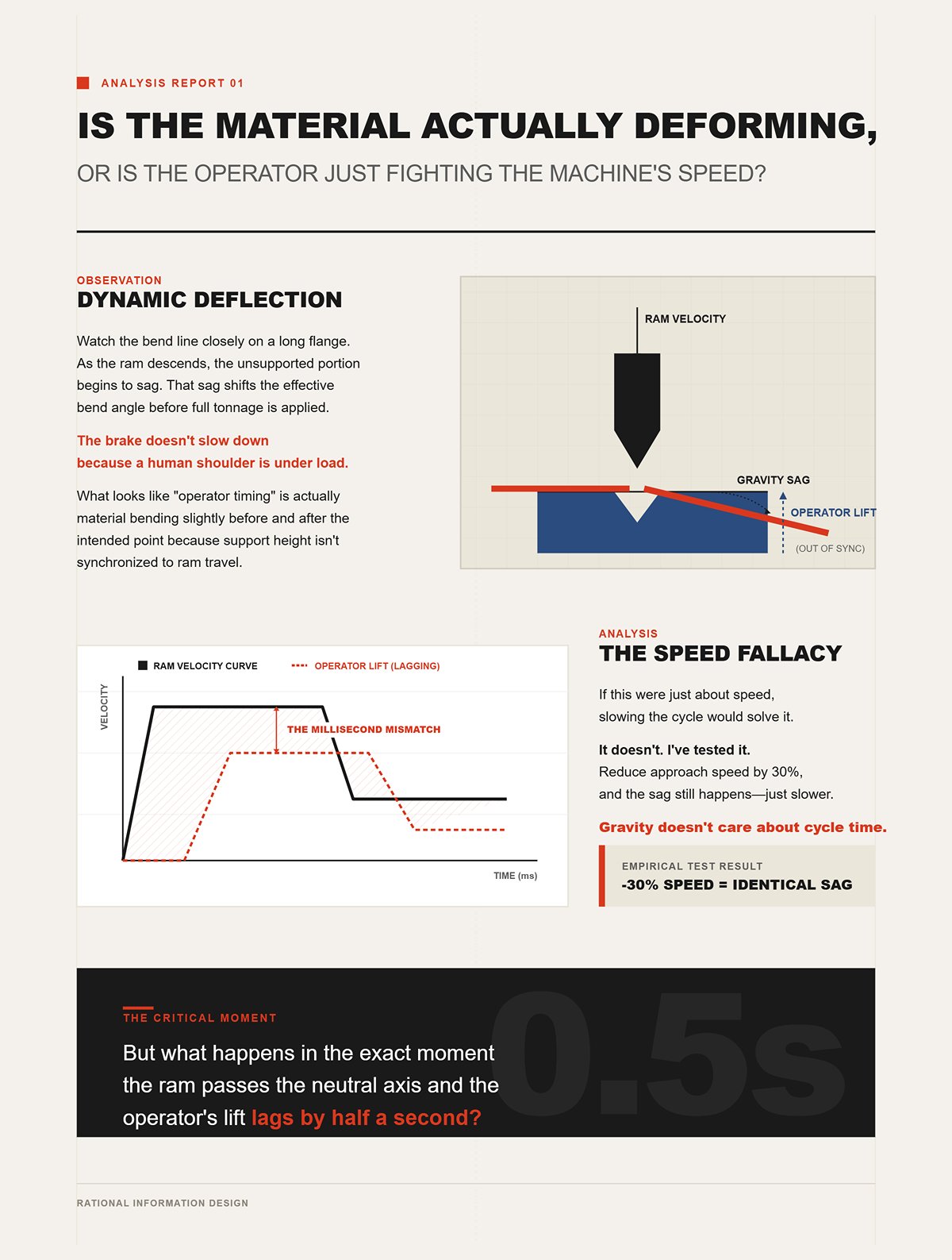
Watch the bend line closely on a long flange. As the ram descends, the unsupported portion begins to sag. That sag shifts the effective bend angle before full tonnage is applied. The operator lifts to counter it, but he can’t match the ram’s velocity curve millisecond for millisecond.
The brake doesn’t slow down because a human shoulder is under load.
What looks like “operator timing” is actually dynamic deflection—material bending slightly before and after the intended point because support height isn’t synchronized to ram travel.
If this were just about speed, slowing the cycle would solve it. It doesn’t. I’ve tested it. Reduce approach speed by 30%, and the sag still happens—just slower. Gravity doesn’t care about cycle time.
This is where most shops stop thinking. They call it a training issue.
But what happens in the exact moment the ram passes the neutral axis and the operator’s lift lags by half a second?
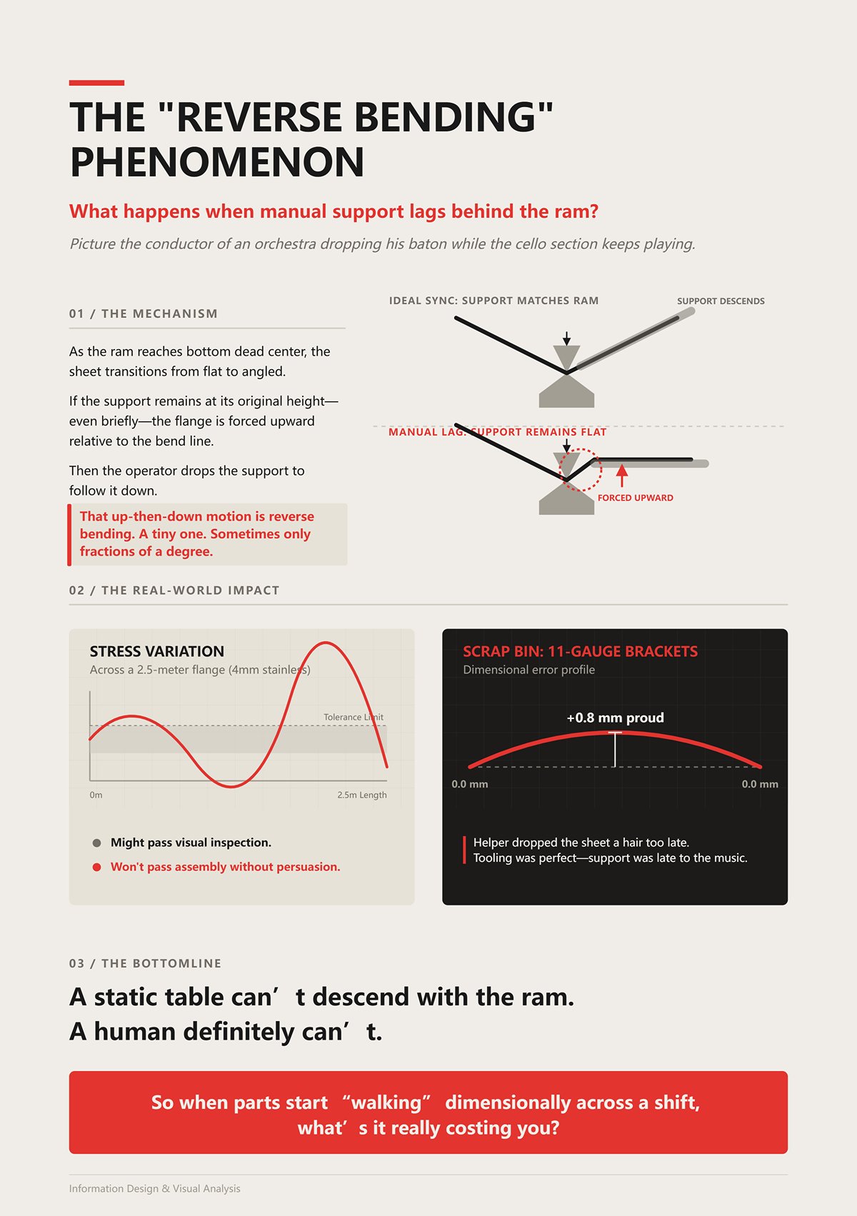
Picture the conductor of an orchestra dropping his baton while the cello section keeps playing. That’s manual support lag.
As the ram reaches bottom dead center, the sheet transitions from flat to angled. If the support remains at its original height—even briefly—the flange is forced upward relative to the bend line. Then the operator drops the support to follow it down.
That up-then-down motion is reverse bending. A tiny one. Sometimes only fractions of a degree.
Do that across a 2.5-meter flange in 4 mm stainless, and you introduce stress variation along the length. It might pass visual inspection. It won’t pass assembly without persuasion.
Scrap Bin: I’ve seen 11-gauge carbon steel brackets that measured perfect at the ends and were 0.8 mm proud in the center because the helper dropped the sheet a hair too late. We torched them out and started over. Not because the tooling was wrong—but because the support was late to the music.
A static table can’t descend with the ram. A human definitely can’t.
So when parts start “walking” dimensionally across a shift, what’s it really costing you?
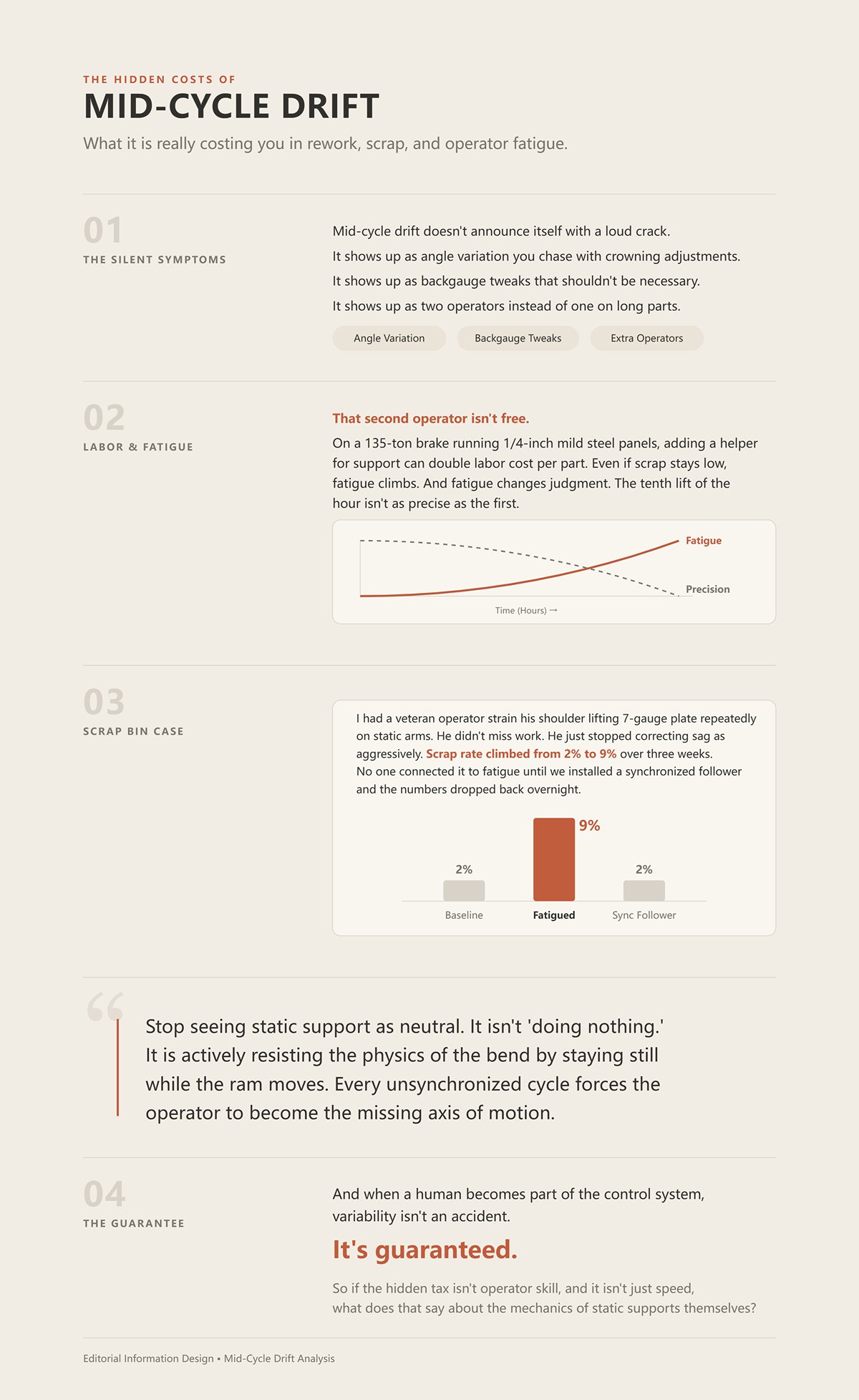
Mid-cycle drift doesn’t announce itself with a loud crack. It shows up as angle variation you chase with crowning adjustments. It shows up as backgauge tweaks that shouldn’t be necessary. It shows up as two operators instead of one on long parts.
That second operator isn’t free.
On a 135-ton brake running 1/4-inch mild steel panels, adding a helper for support can double labor cost per part. Even if scrap stays low, fatigue climbs. And fatigue changes judgment. The tenth lift of the hour isn’t as precise as the first.
Scrap Bin: I had a veteran operator strain his shoulder lifting 7-gauge plate repeatedly on static arms. He didn’t miss work. He just stopped correcting sag as aggressively. Scrap rate climbed from 2% to 9% over three weeks. No one connected it to fatigue until we installed a synchronized follower and the numbers dropped back overnight.
Here’s the cognitive shift I want you to make:
Stop seeing static support as neutral.
It isn’t “doing nothing.” It is actively resisting the physics of the bend by staying still while the ram moves. Every unsynchronized cycle forces the operator to become the missing axis of motion.
And when a human becomes part of the control system, variability isn’t an accident.
It’s guaranteed.
So if the hidden tax isn’t operator skill, and it isn’t just speed, what does that say about the mechanics of static supports themselves?
On a 135-ton hydraulic brake bending a 3-meter sheet of 4 mm stainless, watch the first 50 millimeters of ram travel. The punch hasn’t fully engaged. The sheet is still mostly flat. The static front arms are fixed at one height. Gravity is already pulling the free end down.
The operator’s hands come up before the tonnage does.
That’s the design flaw in plain sight: a static support has one degree of freedom—up or down when you manually set it. The ram has a programmed velocity curve, position feedback, and repeatability measured in hundredths of a millimeter. Once cycle starts, only one of them is moving with intent.
The part comes out with a subtle twist.
Scrap Bin: I ran a 10-gauge carbon steel run—2.4-meter flanges—on fixed arms years back. We slowed the approach, reduced tonnage ramp, even adjusted crowning. The first five parts were fine. By part fifteen, the angle was drifting 0.6 degrees high at one end. Nothing changed in the program. What changed was how aggressively the operator lifted as fatigue set in. The “support system” was a human spine.
A static arm doesn’t just fail to help; it forces the operator to close a control loop the CNC thinks it already owns. You now have two controllers acting on one sheet: the brake driving the bend line down, and the operator pushing the free end up. They are not synchronized, and they never will be.
But what if the machine and the support were fighting each other from the start?
When the brake accelerates through mid-stroke, the sheet’s center of gravity shifts as the flange begins to form. The load on the support changes dynamically. A static arm cannot anticipate that shift. An active follower, even a basic pneumatic unit rated to 380 kg, is built to rise and descend with ram position. It doesn’t eliminate counter-bend. It reduces the human guesswork that causes it.
If one system is position-controlled and the other is muscle-controlled, who do you think wins that argument at 20 mm per second?
Take a common setup: 6 mm mild steel, 48 mm V-die opening—right in that 8-times-thickness rule most shops follow. As the punch descends into the V, the sheet doesn’t rotate around some imaginary line in space. It pivots around the contact points at the die shoulders. That pivot location is fixed by die geometry.
Now look at a typical static front support. The arm pivots from a bracket bolted to the machine frame, often 300 to 600 mm in front of the die line. Its arc of motion—if it has one at all—has nothing to do with the V-opening geometry.
Those two arcs are not concentric. They don’t even share a center.
Scrap Bin: We bent 1/4-inch aluminum tread plate over a 2.5-meter length using a 60 mm V-die. Static table set flush at start. As the flange formed, the sheet’s natural rotation wanted to follow the die shoulders. The table, fixed in space, forced the flange to ride up slightly before dropping. The result was a 1.2 mm bow along the flange length. We blamed material memory. It was geometry conflict.
If the support’s effective pivot point doesn’t track the die’s pivot line, you are bending the sheet twice—once around the die as intended, and once against the support as it resists that rotation. That second bend is small. Fractions of a degree. Across 3 meters, fractions become millimeters.
Active followers are designed to translate vertically in coordination with ram travel, keeping contact near the sheet’s changing tangent as it rotates about the die. They don’t magically align every geometry variable—die width, sheet width, flange length—but they remove the fixed, conflicting arc that static arms impose.
Shop Floor Verdict: If your support’s pivot geometry doesn’t move with the die’s pivot geometry, you are building reverse stress into every long flange.
So even if geometry explains the double-bend effect, what happens when timing enters the picture?
Consider a mechanical press brake running faster mid-stroke than at approach—common on older flywheel-driven machines. The ram might cover the last 20 mm before bottom dead center in a fraction of a second. That velocity curve is predictable. Repeatable.
A static support has zero velocity profile. It is stationary until a human reacts.
But what happens in the exact moment the ram passes the neutral axis and the operator’s lift lags by half a second?
That half-second is where CNC precision dies.
The sheet transitions from elastic deformation to plastic flow around the neutral axis—the layer within the thickness that neither stretches nor compresses. As it passes that point, the flange angle changes rapidly. If support height doesn’t descend in sync, the flange is momentarily over-lifted. When the operator drops his hands, the material springs back unevenly along the length.
Scrap Bin: On a 90-ton brake bending 7-gauge plate, we tried compensating for sag by pre-lifting the free end higher than level. It “worked” on short flanges. On 2.8-meter parts, the center hit neutral axis milliseconds after the ends due to slight material thickness variation. The support correction was already mistimed. We chased a 0.9-degree inconsistency across 40 parts before admitting the problem wasn’t tonnage—it was lag.
You can slow the machine. Gravity still acts. You can train the operator. Reaction time still varies—typically 200 to 300 milliseconds for visual-motor response under load. The brake doesn’t care.
A synchronized follower—whether pneumatic or servo—ties its vertical motion to ram position, not human perception. Yes, it still requires setup. Yes, engagement must be verified with that LED contact indicator some systems use. Presence isn’t the same as contact. But once engaged, its speed matches the machine’s commanded motion.
On a CNC brake capable of ±0.01 mm ram repeatability, relying on a static arm with ±human timing is not thrift. It is sabotage.
Shop Floor Verdict: If your support cannot match the ram’s position and speed, your CNC accuracy stops at the die line—and everything beyond it becomes guesswork.
A few months back I timed a 3/16-inch aluminum bend on a modern CNC brake. From approach to bottom, the last 18 mm of ram travel took 0.6 seconds. Not slow. Not violent. Just fast enough that if the follower hesitates, the sheet feels it immediately.
That’s the benchmark. If a follower can’t track that 0.6-second descent without overshooting or lagging, it isn’t support—it’s delayed interference.
Static arms already lost this fight because they don’t move. Now the real question is subtler: when the ram accelerates, decelerates, and corrects in real time, what kind of drive can stay in tempo without inventing its own timing problems?
Think of the ram as the conductor. The follower has one job—play in perfect tempo. Pneumatic and servo systems both claim they can. Only one does it without guessing.
Picture a 4-foot-wide blank of 10-gauge stainless, short 25 mm flanges, tight V-die. Low center of gravity. Minimal rotation. In that narrow case, a fixed arm set dead level might behave.
But now stretch that part to 2.5 meters and push the flange to 120 mm. The part’s mass swings outward as the bend forms. The rotation accelerates near the neutral axis. The support must descend in a controlled arc relative to die contact. A fixed arm doesn’t descend at all.
Scrap Bin: We ran 11-gauge cold-rolled steel brackets, 300 mm wide. Static arm worked fine for the first 20 pieces. Then the job changed—same thickness, but 1.8-meter length. By part eight, we had a 1.4 mm twist at the free corner. Nothing changed in tonnage or tooling. Only length. The arm didn’t fail because it was weak. It failed because geometry and timing scaled while it stayed frozen.
A mechanical arm is not “simple automation.” It is zero automation. It assumes bend speed, sheet weight, and flange length stay in a narrow window. Production work—especially high-mix shops—rarely stays in that window for long.
Shop Floor Verdict: A fixed support can survive short, repeatable parts; it cannot protect material once length, speed, and rotation vary.
Now we add motion. A pneumatic follower uses compressed air pushing a cylinder to raise and lower the support table. In theory, tie the valve signal to ram position and you have synchronization.
In practice, air compresses.
That matters. When the ram accelerates mid-stroke, the control valve opens to exhaust air from the cylinder so the table drops. But the air inside doesn’t evacuate instantly. Hose diameter, regulator flow rate, and even shop air pressure swings—from 95 psi in the morning to 82 psi when three lasers kick on—change response time.
You don’t see a dramatic lag. You see a soft one. A 0.1-second cushion where the table resists before yielding.
Scrap Bin: We installed a pneumatic follower rated for 380 kg under 1/4-inch aluminum sheet, 3 meters long. Morning run was clean. After lunch, compressor cycling increased, line pressure dipped 10 psi. The follower descended a hair slower. Result: a consistent 0.6-degree overbend at the center compared to the ends. Same program. Same operator. Different air behavior.
Compressed air is forgiving and mechanically simple. Fewer electronics. Lower upfront cost. And in shops without upgraded electrical service, it avoids the peak current draw that some all-electric systems demand. But compressed air introduces a living variable—pressure stability—that your CNC ram does not share.
But what if the machine and the support were fighting each other from the start? With pneumatics, they may agree in command but disagree in response time.
Shop Floor Verdict: Pneumatic followers are a massive upgrade over static arms, but their speed is only as stable as your air supply.
A servo-driven follower replaces compressible air with a motor and ball screw or belt drive. Position feedback comes from an encoder. When the ram moves 0.01 mm, the follower can be commanded to move 0.01 mm. No springiness. No pressure decay.
On a 90-ton brake bending 5 mm mild steel over a 40 mm V-die, we profiled the ram speed curve—slow approach, rapid mid-stroke, controlled decel into bottom. The servo follower mirrored that curve within measurable encoder tolerance. The part angle variation across 30 pieces stayed within 0.2 degrees end to end.
That kind of repeatability matters when flange flatness affects downstream welding or when you’re bending pre-finished 14-gauge stainless that cannot be “persuaded” after the fact.
Now the cost side. Servo systems demand cleaner power and more skilled troubleshooting. I’ve seen hybrid servo-hydraulic brakes sidelined by proprietary drive faults with $8,500 repair bills. When electronics fail, you don’t tap them with a wrench and keep running.
So when is it justified?
When scrap costs exceed repair risk. When parts are long enough that a 0.5-degree error translates into visible bow. When material is expensive—say, 3/16-inch 5052 aluminum at today’s prices—and rework isn’t an option.
Shop Floor Verdict: If your tolerance stack or material cost punishes even small timing errors, servo repeatability pays for itself in saved scrap.
A 3-meter sheet of 6 mm mild steel weighs roughly 140 kg. Add dynamic load as it rotates and you momentarily exceed static weight. Many pneumatic followers advertise 300 to 400 kg capacity. On paper, that seems comfortable.
But rated capacity assumes ideal pressure and vertical load. During a bend, the sheet’s center of gravity shifts outward, creating leverage. The cylinder isn’t just lifting weight—it’s resisting torque.
As the ram approaches bottom dead center, load transitions quickly. If the cylinder is near its upper force limit, the air compresses slightly before pushing back. That micro-compression shows up as follower sag.
Scrap Bin: We bent 8 mm plate, 2.4 meters long, on a follower rated at 400 kg. Static math said we were safe. In motion, the table dipped 3 mm mid-bend. The flange angle at center closed 0.8 degrees more than the ends. The cylinder wasn’t undersized by the catalog—it was undersized for the dynamic reality.
Servo systems, by contrast, hold position through motor torque and mechanical drive, not trapped air. They don’t lose height because pressure fluctuates. But they will draw higher instantaneous current under heavy loads, and older shops with limited electrical service feel that surge.
So the trap isn’t just lifting capacity. It’s dynamic control under shifting load.
Shop Floor Verdict: If your parts are long, thick, or torque-heavy, a pneumatic rating on paper may not equal stable support in motion.
The drive question isn’t about luxury. It’s about tempo. A follower that can’t match the ram’s speed curve—especially that 0.6-second descent on 3/16-inch aluminum—doesn’t solve the synchronization problem. It reshapes it.
And once you start changing materials—soft aluminum, springy stainless, high-strength steel—the sheet itself begins exposing every weakness in that drive choice.
A 3‑meter sheet of 20‑gauge 5052 aluminum weighs less than 18 kg. A 3‑meter sheet of 1/4‑inch A36 plate pushes past 180 kg. Put both on the same press brake with the same follower and tell me the physics are identical.
They aren’t even in the same argument.
Aluminum yields early and springs back modestly. Stainless resists, stores energy, and snaps back harder. High‑strength steel hangs on until the last millimeter of stroke, then releases torque into the tooling like a coiled spring. The follower isn’t just holding weight; it’s reacting to how that sheet rotates, accelerates, and unloads during the bend.
When the drive lags, soft material hides it. When the drive hesitates under springback, high‑strength steel exposes it. And when the follower is overbuilt but slow, thin gauge turns it into a launch mechanism.
This is where most shops get it backward. They size followers for kilograms and forget behavior.
But what happens when the material itself becomes the amplifier?
Picture 22‑gauge 304 stainless, 2.5 meters long, bent into a 40 mm flange. The sheet barely weighs 12 kg, but its stiffness-to-mass ratio is high. As the ram descends, the neutral axis shifts toward the inside radius, the free leg starts to rotate, and inertia takes over.
But what happens in the exact moment the ram passes the neutral axis and the operator’s lift lags by half a second?
With a static arm parked 5 mm low, the rotating leg drops, contacts the arm, and rebounds. The part comes out with a subtle twist. Not dramatic. Just enough that the flange rocks on the inspection table.
That’s not a weight problem. That’s a timing problem.
A pneumatic follower with a 0.1‑second response cushion can still overshoot on thin gauge because there’s so little mass to dampen motion. The sheet accelerates faster than the air can stabilize. A servo follower, commanded to track bottom tool height within encoder resolution, moves in tempo with the ram. The sheet never free‑falls, so it never rebounds.
Scrap Bin: We ran 20‑gauge galvanized, 3 meters long, on manual sliding arms rated for 500 kg with polyethylene tops. After 40 parts, 6 had a consistent 1.2 mm flange height variation at midspan. The arms weren’t weak. They were late. We swapped to a synchronized follower, and the variation dropped below measurable tape tolerance.
Light sheets punish delay more than they reward strength.
Shop Floor Verdict: On thin gauge, speed and synchronization prevent whip; raw lifting capacity does nothing.
So if thin material demands agility, what happens when the sheet weighs ten times more?
Take 1/4‑inch A36, 3 meters long. Roughly 185 kg. Now bend a 60 mm flange on a 120‑ton press brake using a 40 mm V‑die. Mid‑stroke, that plate’s center of gravity shifts outward, creating a torque arm roughly half the flange length.
Do the math and you’re no longer supporting 185 kg vertically. You’re resisting a bending moment that tries to pry the follower downward.
Standard sliding support arms rated at 500 kg assume near‑vertical load. Introduce 60 mm of rotating lever arm, and the linear guide sees side load it was never meant to handle. I’ve measured 2–3 mm deflection at the arm tip during dynamic rotation on thick plate. That deflection closes the center angle before the ends.
Scrap Bin: We bent 10 mm mild steel, 2.4 meters long, on extended manual arms with ball transfers. Static rating said safe. Under load, one arm developed a permanent 1 mm downward set at the mounting block. The next 25 parts showed a 0.7‑degree tighter angle in the center. The arm bent before the steel did.
Servo or hydraulic followers designed for in‑table mounting transfer load directly into the brake frame, not through extended cantilevered arms. The structure matters more than the motor here. High‑strength steels—say 6 mm S700—magnify the issue because their higher yield delays plastic deformation, meaning more elastic energy pushes back into the support during rotation.
You can redesign parts—shorter flanges, larger radii—to ease that load. Smart shops do. But when geometry is fixed and tonnage climbs, structure becomes survival.
Shop Floor Verdict: Above moderate plate thickness, cantilevered support arms become bending members themselves; integrated followers tied to the frame carry torque without deflecting.
And even if you solve weight and torque, one more variable waits to ruin your day.
Now switch to 14‑gauge pre‑finished stainless with a No. 4 brushed surface. Weight is manageable—about 40 kg at 3 meters. The customer rejects parts for a single 30 mm scuff.
Manual support arms often use polyethylene or brush inserts. Good for static sliding. But during a synchronized bend, the sheet doesn’t just slide; it arcs. If the follower’s surface has high friction, the sheet drags microscopically as it rotates, especially near bottom dead center where pressure peaks.
I’ve seen shops blame the operator for scratches that were pure tribology—surface friction under load.
Scrap Bin: On 14‑gauge #4 stainless, 2 meters long, we ran a pneumatic follower with steel rollers. After 60 parts, faint linear marks appeared parallel to the bend. The rollers were clean. The issue was micro‑slip as the sheet rotated and the follower hesitated. Switching to non‑marking coated rollers and tightening synchronization eliminated the marks without touching the program.
Here’s the hierarchy: if the lift is mistimed, even the softest brush plate will scuff because the sheet is momentarily unsupported and drops into contact. If the lift is precise but the contact surface is wrong, you’ll preserve angle and ruin finish.
Material sensitivity decides which flaw shows first. Aluminum forgives scratches but exposes angle drift. Stainless hides minor angle variance but punishes friction. High‑strength painted steel does both.
Shop Floor Verdict: Surface protection components matter—but only after the lifting architecture is synchronized; timing errors damage parts before material choice ever gets a vote.
Match the follower to the sheet’s behavior—its mass, stiffness, springback, and surface—and the system plays in tempo with the ram. Ignore that, and you’re not saving money with static supports. You’re forcing the machine and the material to argue in front of every customer.
Which raises the next problem: even if the follower fits the material perfectly, how does it communicate with the press brake well enough to stay in that tempo?
A 3‑meter sheet of 12‑gauge mild steel doesn’t care how expensive your follower looks. It cares whether that follower knows the ram is about to accelerate from 40 mm/sec approach speed to 8 mm/sec forming speed in the next 0.2 seconds.
I’ve stood behind a press brake where the ram dropped 150 mm in 0.6 seconds, and the follower lifted beautifully—just late. The part comes out with a subtle twist. Not because the lift was weak. Because it was guessing.
That’s the divide: is your follower reacting to motion it senses after the fact, or is it moving because the controller told it what’s about to happen?
But what if the machine and the support were fighting each other from the start?
Picture a 135‑ton CNC brake running a 5‑bend sequence on 10‑gauge stainless, 2.5 meters long. The ram position is tracked by linear encoders down to hundredths of a millimeter. The controller already knows the bend allowance, tool height, material springback compensation, and the exact moment it will decelerate before bottom dead center.
Now bolt on a standalone follower that reads ram position through a proximity sensor and moves on its own PLC.
It can see where the ram is. It cannot see where the ram is going.
That difference is everything.
In a fully networked system, the follower receives the same position command the ram does. When the controller shifts from rapid approach to forming speed, the follower’s servo shifts in the same control loop—closed-loop meaning both axes constantly correct based on encoder feedback. They share intent, not just position.
In a standalone retrofit, the follower waits for motion, then responds. Even a 100–150 millisecond lag is enough for a 3‑meter sheet to dip 4–6 mm at midspan during deceleration. On thin 16‑gauge aluminum, that dip rebounds as the ram slows. On 8 mm plate, it transfers torque into the bend line and tightens the center angle.
Scrap Bin: We ran 3 mm 304 stainless, 3 meters long, on a retrofit follower tied only to ram movement via a linear scale tap. Angles at the ends held ±0.3 degrees. The center drifted 0.8 degrees tighter across 30 parts. The follower wasn’t weak. It was late at every speed transition.
If your follower doesn’t know what the ram is about to do, it’s always reacting—and reaction is how parts drift.
Shop Floor Verdict: If timing matters—and it always does—the follower must share the CNC’s command loop, not chase it from behind.
So what about older hydraulic brakes that were never built for that kind of conversation?
Take a 1998 hydraulic brake with a basic NC control—no open communication protocol, no servo bus, just a ram depth stop and backgauge positioning. You can mount a standalone follower with its own controller and store positions per bend step.
For prototype runs—ten parts, single bend—it works fine. The follower lifts to a preset height, holds, then drops. Accuracy can be comparable because the motion profile is simple.
Now run a 4‑station setup with different die heights and variable flange lengths on 11‑gauge hot‑rolled, 2.8 meters long.
Without live bend data—real-time ram speed, tool height offsets, dynamic angle correction—the operator must manually reset follower height per station or rely on stored values that assume identical approach and forming speeds. Any change in tonnage or material batch shifts the timing window.
What happens in the exact moment the ram passes the neutral axis and the operator’s lift lags by half a second?
On older hydraulics, ram speed can vary with oil temperature and load. A standalone follower that expects 12 mm/sec forming speed may see 9 mm/sec on a cold morning. That 3 mm/sec difference over 80 mm of stroke is enough to desynchronize support through the most critical rotation phase.
Scrap Bin: We retrofitted a follower onto a 160‑ton hydraulic brake bending 6 mm A36 at 2.4 meters. Morning shift parts were consistent. After lunch, with oil warmed and ram speed slightly higher, center angles opened 0.6 degrees. Nothing changed in the program. The follower’s timing window did.
Can a standalone unit keep up? Yes—if the job is simple, low volume, and forgiving.
But once bend sequences stack, tool heights change, and tonnage varies, stored positions become assumptions. Assumptions are expensive in steel.
Shop Floor Verdict: Standalone retrofits survive on predictable, simple work; complex multi-bend jobs expose their blind spots fast.
And those blind spots aren’t just about timing.
Walk up to a brake set with four die stations across 3 meters—20 mm V, 40 mm V, hemming die, then a tall gooseneck punch at the far end. That’s how real shops run mixed parts without constant teardown.
Now add a follower that parks 400 mm behind the lower die when not in use.
If it doesn’t communicate with the CNC about station position, it has one safe default: stay low and out of the way. That means between bends, it must fully retract, then rise again to a preset height. Each cycle adds motion time and risk of mistimed re-entry.
Fully networked systems tie follower position to the bend program itself. When the operator selects station three, the controller already knows the die height and commands the follower to a synchronized standby position—clear of tools but within 10–15 mm of engagement height. No guesswork. No full-stroke resets.
Scrap Bin: On a standalone setup, we ran alternating bends between a 30 mm V and a hemming die on 14‑gauge painted steel. The follower had to drop completely between stations to avoid tool collision. Cycle time nearly doubled. Worse, one mistimed rise clipped the die shoulder and gouged the follower arm.
When the follower isn’t integrated into station logic, it becomes a moving obstacle. Operators start avoiding multi-station setups just to keep the follower manageable. That kills the very efficiency the retrofit was supposed to add.
Shop Floor Verdict: If the follower doesn’t know your tool map, it will either slow your cycle or crash into it.
Integration isn’t just software, though. It’s how power and motion are tied together.
I’ve seen two common retrofit architectures.
First: an electrically driven servo follower bolted to the brake frame, powered separately, reading ram motion through a tapped signal or external scale.
Second: a hydraulic follower piggybacking off the brake’s hydraulic circuit with proportional valves.
The electrical servo has precision on paper—encoder resolution, programmable speeds. But if it isn’t tied into the brake’s main control bus, it runs parallel, not together. Two controllers, two feedback loops. When load spikes—say bending 8 mm plate near full tonnage—the brake may micro-adjust ram position for angle control while the follower continues its planned path. That mismatch shows up as midspan angle variation.
Hydraulic piggybacks feel “naturally synchronized” because they share oil. But unless flow is electronically controlled and coordinated through the CNC, pressure changes in the main cylinders alter available flow to the follower. Under high tonnage, follower lift speed can dip exactly when support demand peaks.
Scrap Bin: A third-party hydraulic follower tied into a 200‑ton brake worked flawlessly on 3 mm aluminum. Switch to 10 mm S355 at near capacity, and follower rise slowed during forming. The center of a 2.5‑meter part sagged 5 mm before catch-up. Angles varied 0.7 degrees across the length. The oil line was shared. The timing wasn’t.
Where do they fail? At the moment of highest load and fastest decision-making—when the ram adjusts, decelerates, or compensates.
A fully networked system makes the follower another controlled axis inside the same architecture. One conductor. One tempo. When the ram changes speed, the follower changes because it received the same command.
Shop Floor Verdict: Electrical or hydraulic doesn’t decide success—shared control logic does; without it, you’re running two machines on one sheet.
So now the question isn’t whether a follower is nice to have. It’s whether your material behavior and your machine architecture demand true integration—or let you get away with reaction.
| Section | Content |
|---|---|
| Topic | Electrical vs. Hydraulic Integration: Where Do Third-Party Retrofits Usually Fail? |
| Common Retrofit Architecture 1 | Electrically driven servo follower mounted to the brake frame, powered separately, reading ram motion via tapped signal or external scale. |
| Common Retrofit Architecture 2 | Hydraulic follower piggybacking off the brake’s hydraulic circuit using proportional valves. |
| Electrical Servo – Strength | High theoretical precision (encoder resolution, programmable speeds). |
| Electrical Servo – Weakness | If not integrated into the main control bus, it operates in parallel with separate controllers and feedback loops. Under high load (e.g., 8 mm plate near full tonnage), brake micro-adjustments can cause mismatch, resulting in midspan angle variation. |
| Hydraulic Piggyback – Strength | Feels naturally synchronized due to shared hydraulic oil system. |
| Hydraulic Piggyback – Weakness | Without electronic flow control coordinated through CNC, pressure shifts in main cylinders affect follower flow. Under high tonnage, lift speed may drop when support demand peaks. |
| Scrap Bin Case | Third-party hydraulic follower on 200-ton brake performed well on 3 mm aluminum. When switching to 10 mm S355 near capacity, follower rise slowed during forming. A 2.5-meter part sagged 5 mm before recovery; angle variation reached 0.7°. Shared oil line, but uncoordinated timing. |
| Failure Point | Failures occur during highest load and fastest decision-making moments—when the ram adjusts, decelerates, or compensates. |
| Fully Networked System | Integrates follower as a controlled axis within the same architecture. One control system, synchronized commands. Ram speed changes and follower response occur simultaneously. |
| Shop Floor Verdict | Success depends on shared control logic—not whether the system is electrical or hydraulic. Without integration, it’s effectively two machines handling one sheet. |
| Core Question | Not whether a follower is optional, but whether material behavior and machine architecture require true integration—or can tolerate reactive operation. |
You don’t decide on a fully integrated follower because it’s impressive.
You decide because your material, your machine, and your production mix leave you no other stable option.
The non-obvious part is this: the tipping point isn’t weight alone. It’s when sheet mass, flex, and bend sequencing exceed what a human and a reactive support can correct in real time. When that happens, synchronization stops being an upgrade and starts being basic tooling.
So where is that line in your shop?
Take a 3.0‑meter blank of 10‑gauge A36. Roughly 38 kg per square meter. At 1.5 meters wide, you’re holding north of 170 kg before the first bend. That sheet doesn’t just weigh more — it stores energy as it rotates.
As the ram drives past the neutral axis, the center wants to drop. Not because your operator is weak. Because gravity is constant and steel has memory.
A static front support rated at 380 kg on linear guides can carry that load. It can glow with LED contact indicators. It can slide smoothly. But it cannot anticipate rotation. It waits for the sheet to move before it reacts.
Scrap Bin: We ran 8‑gauge S355 at 2.8 meters on a brake with heavy-duty static supports rated well above the sheet weight. Capacity wasn’t the problem. Mid-bend, the center sagged 6 mm before the operator and support corrected. End angles read tight. Center angles opened 0.9 degrees. We didn’t overload the support. We outran it.
Now shift to 2 mm 304 stainless at 1.2 meters. Under 25 kg total. On an electric press brake with tight angle control, flex is minimal. Rotation is tame. The operator can guide it with fingertips.
Same shop. Two completely different physics problems.
Shop Floor Verdict: When sheet mass and flex create mid-bend rotation that a human cannot counter instantly, you are sizing for synchronization, not lift capacity.
But material doesn’t act alone. It bends inside a machine with its own limits.
A mechanical press brake running high-speed single-hit parts at fixed stroke depth is predictable. Stroke timing rarely changes. If you run 3 mm aluminum brackets all day, a standalone servo follower tied to ram position may keep up well enough.
But put that same follower on a modern hydraulic with dynamic crowning and real-time angle correction, and things shift. The ram adjusts speed mid-stroke. It compensates for springback. It micro-corrects depth.
If the follower isn’t inside that same control loop, it’s guessing.
Scrap Bin: We retrofitted a servo follower onto a 220‑ton hydraulic bending 6 mm 304 stainless with angle correction active. During heavy bends, the CNC slowed the ram near bottom dead center to hit target angle. The follower, reading a delayed analog signal, continued its programmed rise. The part lifted off the die shoulder, then settled back. Final variation: 0.7 degrees across 2.5 meters. The follower was precise. It just wasn’t invited to the conversation.
Now consider a high-precision electric brake bending 1.5 mm galvanized. Electric drives give repeatable stroke and tight positional control. But loads are low and flex minimal. Here, integration may add cost without solving a real problem.
Shop Floor Verdict: The more your brake adjusts in real time under load, the more your follower must share its control architecture or risk fighting it.
But machines and materials still don’t answer the financial question. Production mix does.
Are you running long batches of identical parts, or 40-part jobs that change tools every hour?
A standalone retrofit survives on repetition. One die height. One bend sequence. Minimal station changes.
Now add four stations across 3 meters: 20 mm V, 40 mm V, hemming die, tall gooseneck punch. Add mixed materials: 4 mm mild steel in the morning, 10‑gauge stainless after lunch. Add operators rotating shifts.
Each change forces the follower to reset positions, clear tooling, and re-engage.
Scrap Bin: On a job mix of 12‑gauge painted steel panels alternating between two die stations, our standalone follower had to fully retract 300 mm between bends to avoid collision. Cycle time stretched from 42 seconds to 71. One mistimed return scratched a finished face. We didn’t lose because the follower was weak. We lost because it wasn’t context-aware.
Future growth makes this sharper. If your quoting pipeline shows longer parts, thicker plate, tighter tolerances, or more multi-bend assemblies, you are stacking variables that punish lag.
Shop Floor Verdict: If your schedule rewards flexibility and multi-station efficiency, only a follower integrated into the bend program protects both cycle time and part quality.
So when does all this cross the line?
Here’s the lens I use now as an auditor.
If one operator cannot physically and consistently counter sheet rotation during the most demanding bend — without rushing, bracing, or guessing — you have exceeded human bandwidth. That’s the first threshold.
If your brake modifies ram motion in response to load or angle feedback, and your follower does not receive the same command data in the same cycle, you have architectural conflict. That’s the second threshold.
If your production mix requires multi-station setups where retract-and-reset motion adds measurable cycle time or collision risk, you have operational friction. That’s the third.
Cross one threshold, and a retrofit might survive. Cross two, and you’ll start seeing angle drift, surface damage, or creeping cycle time. Cross all three, and calling a synchronized follower a “luxury” is like calling backgauges optional.
Scrap Bin: A shop bending 10‑gauge stainless at 3 meters on a 320‑ton hydraulic added an integrated, networked follower after years of fighting center-angle variation around 0.8 degrees. Same material. Same tooling. Variation dropped under 0.2 degrees, and two-person handling became one. Labor shifted to the next operation. The follower didn’t add capability. It removed conflict.
The non-obvious takeaway is this: you don’t justify a networked follower by peak sheet weight. You justify it when material behavior, machine intelligence, and production complexity converge beyond what reactive support can correct in real time.
Shop Floor Verdict: When sheet mass, dynamic ram control, and multi-station workflows overlap, a fully integrated follower stops being optional and becomes structural to the bending process itself.
Look at your heaviest, longest, most complex job scheduled this quarter.
Now ask: is your current support cooperating with the ram — or reacting to it?


