

Last winter I watched a good operator lose eight minutes before he even touched the ram.
He needed the fourth die in a stack. To reach it, he pulled off three 4-foot segments, set them on the floor, grabbed the bottom piece, then restacked the rest. Eight minutes. On a day with twelve changeovers.
That cart “held everything.” That was the selling point.
Fifteen minutes of hunting per shift is roughly 1.25 hours a week. At $75 burdened labor, that’s over $4,800 a year per operator. And that’s before we talk about dropped segments or chipped shoulders.
Vendors sell capacity like it’s horsepower: “Holds 30% more tooling.” “Maximizes vertical space.” On paper, that sounds like efficiency.
Vendor Promise: More tools per cart equals fewer trips to the rack. Shop Floor Reality: More tools per slot equals more unstacking, more double-handling, more micro-delays that stack up faster than the dies themselves.
In a military armory, rifles aren’t piled in crates because it saves square footage. They’re staged so a soldier can grab the exact one, instantly, without disturbing the rest. Press brake tooling is no different. We’re not warehousing steel. We’re deploying precision edges under time pressure.
So what actually happens when density wins?
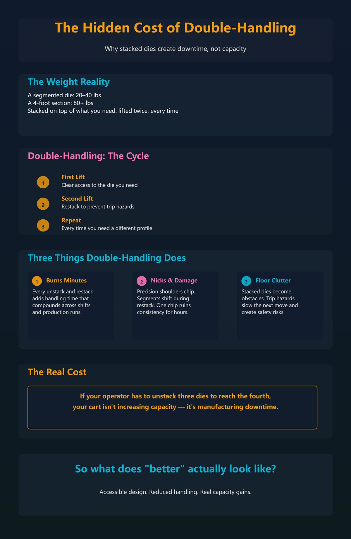
A segmented die weighs 20 to 40 pounds. A 4-foot section can push past 80. Now imagine lifting that twice because it’s sitting on top of what you actually need.
First lift: clear access. Second lift: restack so it doesn’t become a trip hazard.
That’s double-handling. Every time.
Double-handling does three things: it burns minutes, increases the chance of nicks on precision shoulders, and creates floor clutter that slows the next move. I’ve personally ruined a punch tip because a stacked segment shifted during restack. One chip turned into inconsistent bends for the rest of the shift.
If your operator has to unstack three dies to reach the fourth, your cart isn’t increasing capacity — it’s manufacturing downtime.
So if “holding more” creates friction, what does “better” actually look like?
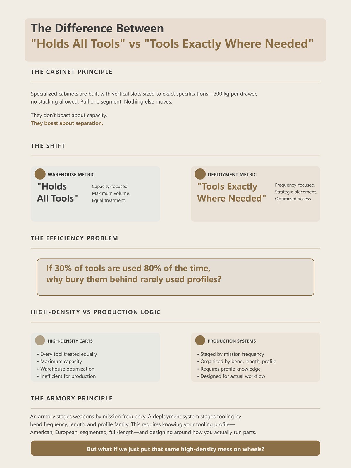
I’ve seen cabinets built for specific tooling standards — vertical slots sized to adaptation width, 200 kg per drawer, no stacking allowed. You pull one segment. Nothing else moves.
They don’t boast about capacity. They boast about separation.
That’s the shift.
“Holds all tools” is a warehouse metric. “Tools are exactly where you need them” is a deployment metric.
If your common jobs use 30% of your tooling 80% of the time, why are those pieces buried behind rarely used profiles? High-density carts treat every tool as equal. Production doesn’t.
An armory stages weapons by mission frequency. A deployment system stages tooling by bend frequency, length, and profile family. That requires knowing your tooling profile — American, European, segmented, full-length — and designing around how you actually run parts.
But what if we just put that same high-density mess on wheels?
I’ve watched shops celebrate a new tooling cart because it “travels with the job.”
What traveled was the bottleneck.
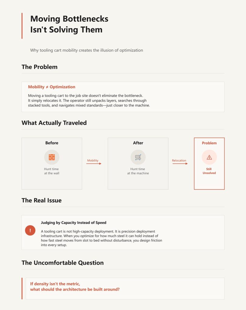
If the cart architecture forces stacking, mixed standards, or buried segments, all you did was relocate the hunt time from the wall to the machine. The operator still unpacks layers. He just does it closer to the ram.
Mobility is not optimization. It’s relocation.
The cognitive shift is this: a tooling cart is not high-capacity deployment. It is precision deployment infrastructure. The moment you judge it by how much steel it can hold instead of how fast steel can move from slot to bed without disturbance, you start designing friction into every setup.
And once you accept that, the real question becomes uncomfortable:
If density isn’t the metric, what should the architecture be built around?
A 20 mm tang does not fit the same rail as a 0.500-inch tang without consequences.
Last year we brought in a new batch of Wila-style punches—20 mm wide tang, dual front and rear grooves for auto-clamping. Beautiful pieces. Ground clean. Buttons for lighter tools, pin-locks for the heavier ones. We parked them on the same cart that had carried American tooling for years: simple horizontal rails sized around the half-inch tang.
On paper, they “fit.” On the floor, they fought back.
The rails didn’t cradle the wider tang evenly. The grooves that the auto-clamp relies on had nothing protecting them. Operators had to angle the punch slightly to clear the lip, then rotate it flat. That’s two motions instead of one. Multiply that by 40 pieces on a changeover.
Fifteen extra seconds per tool is ten minutes gone.
Vendor Promise: “Universal rails accommodate all major tooling styles.” Shop Floor Reality: Universal means every profile is partially unsupported.
When you design a cart around maximum density, you assume tools are just steel shapes with weight. But American, European, and Wila-Trumpf systems are different mechanical interfaces. They engage the ram differently. They seat differently. They extract differently. If the cart ignores that interface geometry, it forces operators to compensate with wrist angles, extra lifts, and careful babying.
And every compensation costs time.
If density isn’t the metric, then architecture has to follow the retention system itself. The cart must respect how the tool locks into the machine—because that same geometry governs how it should sit when idle. If it doesn’t, you’re not staging tools for deployment. You’re parking them in friction.
So what happens when you mix precision-ground European tooling with rails built around American retention assumptions?
A 13 mm European tang sits narrower and deeper than American. It’s designed for more consistent clamping surface along the height. That’s part of why it repeats well.
Now drop that 13 mm tang into a rail designed to cradle a broader 0.500-inch shoulder.
There’s side play.
Not enough to see across the shop. Enough to feel when you grab the segment. The punch rocks slightly. The edge kisses the rail wall. Over time, that micro-contact rounds corners that were ground for accuracy.
You won’t notice it on day one.
You’ll notice it when a bend drifts half a degree and you chase backgauge settings for twenty minutes before realizing the clamping repeatability changed.
American-style tooling already has less clamping surface by design. Frequent swapping accelerates wear because that half-inch tang carries the load on a smaller interface. If your cart forces repeated sliding into oversized slots, you’re adding side abrasion to a system that’s already more sensitive to it.
Vendor Promise: “One cart for mixed fleets.” Shop Floor Reality: Mixed fleets need segregated architecture, not shared rails.
He needed the fourth die in a stack. Now imagine that fourth die is European precision tooling sitting in a slot with clearance built for something wider. Every pull becomes a careful extraction. Careful means slow.
And slow repeated a hundred times a week becomes normal.
If European tooling suffers from lateral slop in American-style rails, what happens when we flip it—when we try to stage Wila-Trumpf auto-clamping tooling on standard rails that ignore the button and groove system entirely?
Wila-Trumpf tooling under roughly 27 pounds often uses spring-loaded safety buttons. Heavier pieces use pin-locks. Both are designed for vertical insertion and positive engagement in the press.
Standard horizontal cart rails don’t account for that hardware.
I’ve watched operators pull a Wila punch straight up, only to have the spring button drag against the rail lip because the rail spacing didn’t clear the button travel. So they tilt it. Then lift. Then rotate.
Three movements where one should do.
Ten seconds here. Twelve there. Forty tools later, you’re behind schedule before the first test bend.
But the real bottleneck isn’t the seconds. It’s the interference. When the cart rail contacts the button housing or the groove edge, operators instinctively slow down to avoid damage. That hesitation is friction baked into the architecture.
But what if we just put that same high-density mess on wheels and park it next to the brake?
Now you’ve relocated the extraction bottleneck to the point of highest time pressure. The operator stands at the machine, job clock running, wrestling a tool out of a rail that was never designed for its retention hardware.
An armory doesn’t design racks that snag the safety selector on every rifle. Why are we okay with carts that snag auto-clamp hardware?
If retention systems dictate vertical clearance and side support, segment length dictates something else entirely: spacing.
A four-foot die segment weighs enough that you don’t “wiggle it free.” You commit to the lift.
Now imagine lifting that twice because it’s sitting on top of what you actually need.
Long segments change the math. A 12-inch piece can be angled out of a tight slot. A 48-inch segment needs straight-line extraction. That means vertical clearance above and lateral clearance along the full length.
High-density carts cheat this by stacking lengths or mixing segment sizes in shared channels.
Vendor Promise: “Adjustable channels fit all lengths.” Shop Floor Reality: Adjustable channels mean compromise spacing.
If your common work runs 2-foot and 4-foot segments interchangeably, your cart must dedicate lanes that allow single-motion extraction for the longest piece in that family. That often means fewer lanes.
Lower count. Higher speed.
And then there’s closing height. All tools in a setup must share identical closing height—punch to bed space. If your cart mixes risers, spacers, and base dies without architectural separation, operators end up building height corrections at the machine. That’s not deployment. That’s assembly under pressure.
So the architecture question isn’t “How many tools can this cart hold?”
It’s this: For my dominant tooling style—American, European, or Wila—what geometry, clearance, and support does extraction require so that one tool leaves without disturbing another?
When the cart answers that precisely, setup accelerates.
When it doesn’t, every pull is a negotiation.
A 60-pound, 4-foot die binds halfway out of a bare steel channel. The operator lifts, feels resistance, twists slightly to free it, then re-lifts to clear the lip. That’s two extra motions under load, with a precision-ground edge dragging across material never designed to protect it.
Now imagine that twice because it’s sitting on top of what you actually need.
If architecture must follow retention geometry, then a properly designed cart for American tooling carries broad 0.500-inch tangs in matched-width saddles with lateral constraint and open-top clearance for straight-line lift. European 13 mm tang systems demand narrower channels with full-height side support to prevent rocking. Wila-Trumpf auto-clamp tooling requires relief zones that clear spring buttons and pin-lock hardware so extraction is vertical and uninterrupted.
That’s not a preference. That’s mechanical necessity.
Vendor Promise: “Universal high-capacity deployment.” Shop Floor Reality: Retention geometry dictates lane width, side support, and exit path.
The armory analogy holds here. Weapons aren’t piled in crates for maximum density. They’re staged so one can leave without scraping the next.
Fifteen minutes per shift lost to cautious extraction costs roughly $4,000 a year per operator at typical shop labor rates. I’ve seen that time vanish not in walking—but in hesitation.
Vertical racks recover floor space. Some manufacturers cite up to 90% floor recovery and major reductions in walking distance. In tight shops, that matters. But vertical designs often use slide-out shelves with interlocks that prevent multiple drawers opening at once. Safe on paper.
Under changeover pressure, that safety becomes a choke point. A long die sitting upright in a high-density vertical lane requires upward lift plus forward clearance. If the lane spacing is tight, the operator angles the die to escape. The tip contacts the shelf edge. Micro-chips start there.
Drawer systems flip the geometry. The tool lies horizontal. Retrieval becomes a horizontal slide, then lift. For short, segmented punches, drawers protect tips because the cutting edge isn’t bearing weight during extraction. For long dies, though, poorly supported drawers create mid-span deflection. A 4-foot die sagging in the middle rubs its shoulders against the sidewalls as it slides.
So which prevents damage?
Short precision punch segments favor shallow, dedicated drawers with full-length polymer beds and zero stacking. Long heavy dies favor horizontal roller racks with continuous support and straight-line extraction.
Density-focused verticals win on floor space. Deployment-focused horizontals win on single-motion removal. Which metric is actually slowing your setups?
| Aspect | Vertical Racks | Drawer Systems | Impact on Punch Tip Damage |
|---|---|---|---|
| Floor Space Efficiency | Can recover up to 90% floor space; reduces walking distance | Requires more floor space | Vertical racks win on space optimization |
| Retrieval Motion | Upward lift plus forward clearance | Horizontal slide, then lift | Horizontal motion reduces tip contact risk |
| Safety Mechanism | Interlocks prevent multiple shelves opening | Typically single-drawer access | Interlocks can slow retrieval under pressure |
| Changeover Speed | Can create bottlenecks during high-pressure changeovers | Faster single-motion removal | Drawer systems reduce hesitation time |
| Risk for Short Punch Segments | Tight spacing may cause tip contact with shelf edge | Shallow, dedicated drawers protect cutting edges | Drawers better prevent micro-chipping for short punches |
| Risk for Long Dies | Upright storage may require angling during removal | Poor support can cause mid-span deflection | Vertical racks risk edge contact; poorly designed drawers risk sagging |
| Support for Long Dies | Depends on lane spacing; may lack continuous support | Requires full-length support to prevent sag | Continuous roller support preferred |
| Best Use Case | High-density storage where floor space is critical | Fast deployment and precision tool protection | Match layout to tool type and setup priority |
| Overall Advantage | Maximizes storage density | Optimizes single-motion extraction | Choice depends on whether space or setup time is the priority |
A ground punch tip contacting bare steel at 60 pounds of point load is not neutral. Steel on steel under sliding load creates adhesive wear. Microscopic high points shear. That’s not theory—that’s tribology.
Bare steel rails are cheap. They’re also harder than the operator’s patience.
UHMW (ultra-high-molecular-weight polyethylene) has a low coefficient of friction and high abrasion resistance. It won’t gall against tool steel. When a die rests on UHMW, contact stress distributes slightly as the material yields microscopically. That protects edges.
Polyurethane sits in between. Higher load capacity than UHMW, more impact resistance, but slightly higher friction depending on durometer. Good for vertical bump protection. Less ideal for long sliding extractions if the surface grips.
Vendor Promise: “Powder-coated steel for durability.” Shop Floor Reality: Durability for the cart is irrelevant if it abrades $1,200 tooling.
For American tooling with broader tang shoulders, UHMW-lined saddles prevent side wear during lift-out. European systems benefit from full-height polymer sidewalls to eliminate rocking contact. Wila systems need relieved pockets around button housings, lined to prevent drag during disengagement.
Contact material isn’t cosmetic. It defines whether deployment is protective or abrasive.
A 70-pound die resting on a flat steel rail requires more force to initiate movement than the same die on low-friction polymer. That initial breakaway force is where operators jerk.
Jerking is where drops happen.
When horizontal roller extraction is used—properly rated rollers with full-length support—the required force drops dramatically. The die moves in a controlled path. No twisting. No re-gripping mid-span. Ergonomic strain decreases, which directly reduces the likelihood of edge strikes against adjacent tools.
But friction isn’t just about physics. It’s about behavior.
If extraction feels resistant, operators slow down. They adjust grip. They hesitate near adjacent edges. That cognitive load compounds across 30 tools in a changeover.
High-density vertical lanes often increase friction through tight tolerances meant to prevent sway. That stabilizes during deployment-in, but penalizes deployment-out. Horizontal roller systems reduce friction but require precise alignment to avoid skew.
So the question becomes simple: does your cart require forceful correction during extraction, or does it guide the tool out in one continuous motion?
If the operator has to fight the material, you’ve engineered resistance into the workflow.
A cart rated for 1,000 pounds sounds impressive. Empty weight: roughly 265 pounds in a common heavy-duty model. Add 500 pounds of tooling and push it across a slightly uneven concrete floor.
Now watch the frame twist.
I’ve tested carts that felt solid at 300 pounds and unstable at 500. Not tipping—flexing. Drawers misalign slightly. Roller tracks bind. Suddenly the smooth extraction you paid for becomes a two-handed yank because the chassis racked under load.
Weight limits are static numbers. Deployment is dynamic.
When fully loaded, the center of gravity rises—especially with vertical racks. Push force increases. On uneven floors, one caster unloads briefly, shifting weight diagonally through the frame. That micro-racking changes rail alignment by millimeters. Millimeters matter when your retention clearance is tight by design.
Vendor Promise: “1,000 lb capacity.” Shop Floor Reality: Capacity without torsional rigidity is a mobility liability.
A properly engineered deployment cart overbuilds the chassis relative to rated load, uses cross-bracing to resist torsion, and positions heavy lanes low to keep the center of gravity down. Otherwise, your carefully engineered contact materials and lane geometries degrade the moment the cart moves under real weight.
And that raises the next question.
If architecture and materials can protect precision edges and accelerate extraction in a static position, what happens when you introduce motion into the system itself?
Every time a 600-pound cart crosses a floor seam, torsion spikes through the frame and your carefully aligned lanes go out by a millimeter.
That’s how motion amplifies static design flaws. In a parked position, low-friction polymer beds, tight retention clearances, and balanced vertical lanes behave exactly as engineered. The moment you introduce acceleration, deceleration, and diagonal load shifts from uneven concrete, the chassis becomes part of the tooling interface. One caster unloads. Weight transfers. Rails skew slightly. Now the die that used to glide needs a corrective tug.
And corrective tugs chip edges.
Vendor Promise: “Mobile flexibility between machines.” Shop Floor Reality: Flexibility means every bump is a live load test of your alignment tolerances.
We treat wheels as neutral. They aren’t.
If your cart travels farther than your operator during a shift, you’ve redesigned your shop around wheels instead of workflow.
Ten feet is roughly the distance from brake bed to adjacent staging area in a sane layout.
Within that radius, mobility can reduce steps without introducing meaningful instability—short, controlled pushes over known floor conditions, low acceleration, predictable stops. The cart behaves like a repositioned workstation, not a transport vehicle.
But stretch that to 40 feet across expansion joints, air lines, and traffic lanes, and the physics change. Momentum builds. Operators steer with one hand while clearing obstacles with the other. Braking forces shift load forward. The center of gravity rises as upper lanes fill. What was deployment becomes transportation.
He needed the fourth die in a stack.
Now imagine lifting that twice because it’s sitting on top of what you actually need.
Short-haul mobility eliminates walking. Long-haul mobility adds handling cycles disguised as convenience.
Vendor Promise: “Move your entire setup anywhere in the shop.” Shop Floor Reality: The farther it rolls, the more your protective architecture behaves like cargo restraint instead of precision deployment.
So the real question isn’t “Does it roll?” It’s “How far, how often, and under what load?”
Fifteen minutes of hunting per shift costs more in labor than a set of industrial casters costs in steel.
A stationary high-density cabinet—properly engineered with full-extension shelves and monorail support—cuts search time because nothing moves except the drawer. No torsion. No caster deflection. Gravity is constant. The tooling stays aligned with the structure that supports it.
But density tempts you to overpack. And overpacking reintroduces double-handling.
Dedicated point-of-use carts solve a different problem. They stage only the next job’s tools, sequenced in removal order, positioned at waist height, with clear lanes and zero stacking. Low density by design. High clarity. They don’t try to hold everything. They exist to deploy what’s next.
But what if we just put that same high-density mess on wheels?
Now you’ve combined the worst traits: packed lanes that resist extraction and a mobile base that flexes under load. Movement magnifies density penalties. Stationary cabinets tolerate density because the frame never racks. Mobile carts demand restraint because the frame always does.
Mobility is not a feature. It’s a stress multiplier.
Eight minutes of walking per changeover across four brakes adds up to hours per week.
In a multi-brake shop, pure centralization forces operators to migrate to a tooling “armory” for every setup. Pure mobility floods the floor with overloaded carts acting like roaming warehouses.
A hybrid hub-and-spoke model splits the difference. The hub is a stationary, high-density cabinet engineered for stability and search efficiency. It holds the full tooling inventory. The spokes are low-capacity, torsion-resistant carts staged per job, loaded intentionally from the hub, traveling only within that 10-foot rule at each brake.
Think military armory. Weapons aren’t piled in crates for maximum density—they’re staged for rapid, damage-free deployment under pressure. The armory is fixed. The mission kit is assembled deliberately, then carried where needed.
The mistake is assuming every tool must live on wheels.
Measure the distance from hub to brake. Measure how often carts cross traffic lanes. Measure how many tools on a cart are never touched during a shift. Those numbers tell you whether mobility is solving bottlenecks—or quietly creating them.
And once you can measure it, the question stops being convenience.
It becomes return on investment.
Twelve minutes per changeover at $30 per hour is $6 in labor. Run five changeovers a day, 240 days a year, and you’ve burned $7,200 because your tooling deployment system fights you instead of feeding you.
That’s the math everyone avoids because carts get labeled “overhead,” not “throughput drivers.” We’ll run it straight: mobility only delivers ROI when the minutes it saves exceed the minutes it quietly adds through double-handling, hunting, and damage. Not what you feel. What you can time with a stopwatch.
So how do you calculate when wheels make you money instead of costing you?
Fifteen minutes of “it’s around here somewhere” costs $7.50 per operator per shift at $30 per hour. Multiply that by two operators and 240 days, and you’re staring at $3,600 a year in search time alone.
But you don’t start the clock at unclamp. You start it when the last good part of Job A comes off the brake. Then you stop it when the first verified good part of Job B hits the pallet. That’s real changeover time.
Break it into components:
Vendor Promise: “High-capacity cart reduces trips.” Shop Floor Reality: Safety interlocks allow one 4,000-pound shelf open at a time, so retrieval becomes sequential, not parallel.
Time each piece for a week. Hypothetical example: your team believes changeovers average 20 minutes. Stopwatch says 32. Of that, 6 minutes are tool hunting, 4 are unstacking to reach the correct die, 3 are reseating punches that don’t slide cleanly because the cart racked crossing an expansion joint.
You didn’t have a machine problem. You had a deployment problem.
Now ask the uncomfortable question: if precision-ground tooling and hydraulic clamping can cut machine-side setup to near single digits, but your cart injects 10 minutes of friction back in, where did the capital investment actually go?
One chipped gooseneck punch can run $800 to $1,500 depending on length and profile. That’s not catalog scare talk. I’ve signed the replacement order after we dragged one across a flexed rail.
Now imagine lifting that twice because it’s sitting on top of what you actually need.
Damage rarely happens during bending. It happens during handling. A cart loaded for maximum density raises center of gravity. Hit a floor seam. One caster unloads. Frame twists a millimeter. The hardened edge kisses steel instead of polymer.
Vendor Promise: “40% more capacity per footprint.” Shop Floor Reality: Higher stacking equals more lifts per retrieval, which equals more edge exposure under load.
If your shop chips two punches a year because of chaotic handling, and each averages $1,000, that’s $2,000 annually. Add the lost production time waiting for a replacement or regrind. Add the quality risk if someone runs it anyway.
Insurance isn’t about frequency. It’s about consequence.
A purpose-built deployment cart with separated lanes, retention geometry matched to your tang style, and a wide wheelbase that resists torsion doesn’t just save minutes. It reduces edge contact events. Fewer edge contacts mean fewer replacement orders.
When you price one chipped gooseneck against a year of faster changeovers, the “expensive” cart starts looking like a deductible you’re already paying.
But how many minutes does it actually need to save to justify itself?
Let’s run a clean hypothetical.
Premium purpose-built cart: $8,000. Operator labor: $30 per hour. Shifts: 240 per year.
To pay back $8,000 in one year on labor alone, you need to recover about 267 labor hours. That’s roughly 1.1 hours per shift.
Sounds impossible until you distribute it.
If you run four changeovers per shift, that’s about 16–17 minutes saved per changeover across the team. Not per operator. Per event.
Where do 17 minutes hide?
That’s 17.
If your stopwatch audit shows only 6 recoverable minutes per changeover, the cart doesn’t pay back in year one on labor alone. Now you factor in one avoided $1,000 punch replacement and the math shifts again.
This is the non-obvious part: ROI isn’t about whether the cart rolls. It’s about whether your tooling profile, changeover frequency, and handling pattern create enough friction that engineered deployment removes measurable minutes and measurable damage.
Think armory. Weapons aren’t piled in crates for maximum density—they’re staged for rapid, damage-free deployment under pressure. The armory is fixed. The mission kit is assembled deliberately.
Your hub is fixed. Your spoke is intentional. Your cart is not a box with wheels; it’s a time-and-risk conversion device.
So the lens changes. You don’t ask, “Is this cart expensive?”
You ask, “How many edge contacts and handling minutes are we buying back per shift—and are we disciplined enough to measure them?”


