

Last month a kid rolled a “complete press brake kit” into my shop in the back of a hatchback. Two steel side plates, a bottle jack, a handful of bolts, and a promise printed on the box: Bend 1/4-inch plate at home.
He set it on my floor like a model train set on Christmas morning. All the pieces were there. All he had to do was bolt it together.
That’s the illusion.
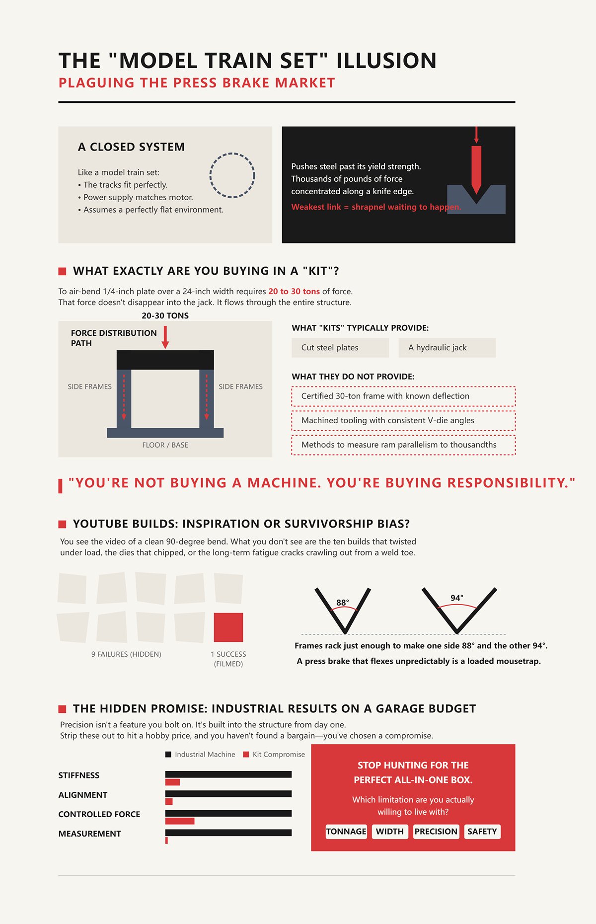
When you buy a model train set, you’re buying a closed system. The tracks fit. The power supply matches the motor. The instructions assume nothing about your basement except that it’s flat.
A press brake is not a closed system. It’s a machine that fights back. It pushes steel past its yield strength — that’s the point where metal stops springing back and starts staying bent — and it does it with thousands of pounds of force concentrated along a knife edge.
Hard truth: if any one part of that force path is weak — frame, ram, tooling, fasteners, floor — the weakest link becomes shrapnel waiting to happen.
So when you type “press brake kit” into a search bar, what are you really expecting to show up in the box?
Let’s take that 1/4-inch mild steel claim. To air-bend 1/4-inch plate over, say, a 24-inch width, you’re in the neighborhood of 20 to 30 tons depending on die opening. That force doesn’t disappear into the jack. It flows through the ram, into the side frames, down into whatever you bolted it to.
Most “kits” give you cut plates and a jack. They don’t give you a certified 30-ton frame with known deflection under load. They don’t give you machined tooling with consistent V-die angles. They definitely don’t give you a way to measure ram parallelism to a few thousandths.
You’re not buying a machine. You’re buying responsibility.
And if the box doesn’t include engineering for deflection, alignment, and repeatability, who exactly is supposed to solve that once the steel starts moving?
You’ve seen the videos. A guy welds up a frame from scrap I-beam, slaps in a hydraulic cylinder, bends clean 90s on camera, smiles.
What you don’t see are the ten builds that twisted under load, the dies that chipped, the frames that rack just enough to make one side of the bend 88 degrees and the other 94. Cameras don’t measure taper. They don’t show long-term fatigue cracks crawling out from a weld toe.
Hard truth: a press brake that flexes unpredictably is a loaded mousetrap waiting for your fingers.
The builds that survive to be filmed are the outliers — the fabricator who understands load paths, weld sequence, and stress concentration. If you don’t already know those words in your bones, are you copying a plan… or gambling on luck?
Look at where the real money in press brakes is going right now: multi-axis CNC machines, electric drives with precise backgauges, software that simulates springback before the first bend. Shops pay for that because repeatability is profit.
The kit market whispers something seductive: you can skip all that and still get clean, square, production-worthy bends in a one-car garage.
But precision isn’t a feature you bolt on. It’s stiffness, alignment, controlled force, and measurement — built into the structure from day one. Strip those out to hit a hobby price, and you haven’t found a bargain. You’ve chosen a compromise whether you admit it or not.
So the shift I need you to make is this: stop hunting for the perfect all-in-one box, and start asking which limitation — tonnage, width, precision, or safety margin — you’re actually willing to live with when the ram comes down.
You’re asking the right question now: if the “complete kit” isn’t real, how do you decide what level of capability and risk you’re actually willing to accept?
Good. That’s the moment you stop shopping like a consumer and start thinking like a fabricator.
Last summer I was dialing in a 10-foot industrial brake with fresh seals and calibrated tooling. Ambient temperature in the shop drifted about 12°C from morning to afternoon. That was enough to move bottom dead center — the exact lowest point of the ram stroke — by roughly 0.04 mm. On paper, that sounds microscopic. On a part spec’d at ±0.5° bend tolerance, it was the difference between passing and scrapping.
That machine weighs more than your pickup.
If thermal drift can nudge a climate-controlled, servo-hydraulic brake off target, what exactly do you think a bottle jack in a bolt-together frame is doing while you’re pumping by feel?
You’re not choosing between “cheap” and “expensive.” You’re choosing how much uncontrolled movement you’re willing to tolerate in a system that multiplies small errors into visible ones.
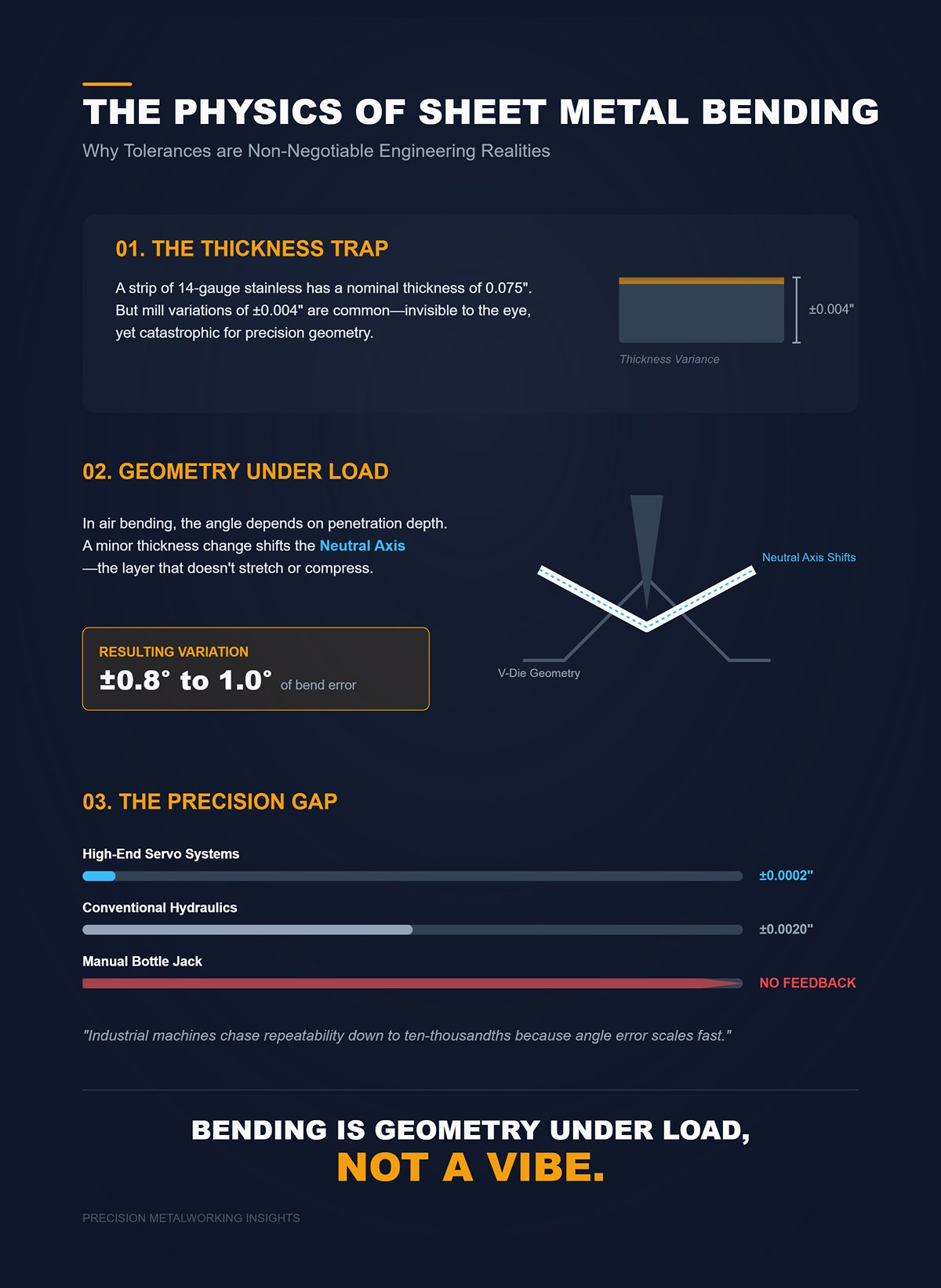
Take a strip of 14-gauge stainless. Nominal thickness might be 0.075 inches. Now imagine the supplier sends you a batch that varies ±0.004 inches across sheets. That doesn’t sound like much — you can barely see it.
In air bending — where the punch presses the sheet into a V-die without bottoming out — bend angle depends on how deep the punch penetrates relative to thickness. A small change in thickness changes where the neutral axis (the layer that doesn’t stretch or compress) sits inside the material. That shifts springback. On stainless, that thickness swing alone can translate into roughly ±0.8 to 1.0° of bend variation if you don’t adjust bottom position.
That’s before we talk about frame flex. Before ram drift. Before tooling wear.
So when a kit promises “90° bends,” what does that even mean? Ninety on what thickness, from which mill, at what temperature, with what penetration depth?
Hard truth: bending is geometry under load, not a vibe.
Industrial machines chase repeatability down to a few ten-thousandths of an inch in ram position because angle error scales fast. High-end servo systems can repeat within about ±0.0002 inches of stroke. Conventional hydraulics might be ±0.002 inches — an order of magnitude looser — and that can mean roughly ±1° swing on a typical air bend.
Your bottle jack has no encoder. No feedback. Just your arm and a pressure gauge.
You see where this goes.
| Section | Content |
|---|---|
| Material Example | 14-gauge stainless steel with nominal thickness of 0.075 inches |
| Thickness Variation | Supplier variation of ±0.004 inches across sheets |
| Bending Method | Air bending (punch presses sheet into a V-die without bottoming out) |
| Key Dependency | Bend angle depends on punch penetration depth relative to material thickness |
| Neutral Axis Impact | Thickness changes shift the neutral axis position, affecting springback |
| Resulting Angle Variation | On stainless steel, ±0.004-inch thickness variation can cause approximately ±0.8° to 1.0° bend variation without bottom position adjustment |
| Additional Variables | Frame flex, ram drift, and tooling wear further affect accuracy |
| Questioning “90° Bends” | Actual bend angle depends on thickness, material source, temperature, and penetration depth |
| Core Principle | Bending is geometry under load, not guesswork |
| Industrial Precision | High-end servo systems repeat within ±0.0002 inches of stroke |
| Hydraulic Precision | Conventional hydraulics repeat within ±0.002 inches of stroke |
| Angle Sensitivity | Stroke variation can result in approximately ±1° angle change in typical air bending |
| Manual Limitation | Bottle jacks lack encoders and feedback systems, relying only on manual force and pressure gauges |
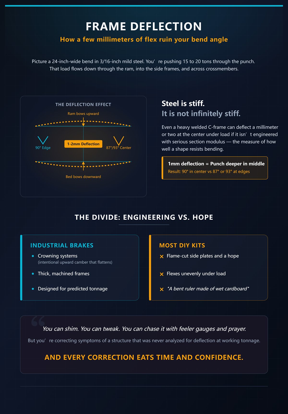
Picture a 24-inch-wide bend in 3/16-inch mild steel. You’re pushing, say, 15 to 20 tons through the punch. That load flows down through the ram, into the side frames, and across whatever crossmember ties them together.
Steel is stiff. It is not infinitely stiff.
Even a heavy welded C-frame can deflect a millimeter or two at the center under load if it isn’t engineered with serious section modulus — that’s the measure of how well a shape resists bending. One millimeter of vertical deflection at midspan doesn’t just mean “a little flex.” It means the punch is deeper in the middle than at the ends. The result? A 90° in the center and 87° or 93° at the edges, depending on compensation.
Industrial brakes fight this with crowning systems — intentional upward camber in the bed that flattens under load — and thick, machined frames designed from day one around predicted tonnage.
Most kits give you flame-cut side plates and a hope.
A frame that flexes unevenly under load is a bent ruler made of wet cardboard.
You can shim. You can tweak. You can chase it with feeler gauges and prayer. But you’re correcting symptoms of a structure that was never analyzed for deflection at working tonnage.
And every correction eats time and confidence.
Now let’s talk about what beginners try when air bending won’t behave: they bottom out.
Bottoming means you drive the punch all the way until the material is forced tightly into the die angle. Instead of angle being controlled by stroke depth, it’s controlled by the tooling geometry. That reduces sensitivity to small ram position errors. Sounds like a solution.
Except bottoming requires significantly more tonnage — often 3 to 5 times what air bending needs for the same material and width. If air bending 1/4-inch plate takes 25 tons, bottoming it can demand numbers that push far beyond a 20-ton jack’s honest capacity.
And that 20-ton rating? That’s peak force at ideal conditions, not sustained load at awkward mid-stroke with side loading from imperfect alignment.
Hard truth: when you run out of stroke control and compensate with brute force, you’re multiplying stress in a system that was already marginal.
On a rigid, purpose-built brake, bottoming is a calculated choice. On a light frame with a bottle jack, it’s desperation — and desperation in hydraulics is how seals blow and frames twist.
So if you can’t hold stroke precisely enough to air bend, and you can’t safely multiply tonnage enough to bottom, what mode are you really operating in?
I’ve seen a 12-ton shop press spit a bearing race across a room when a cheap casting cracked under load. No warning. Just a sharp report and steel moving faster than your reflexes.
Now imagine 20 tons concentrated through a narrow punch tip. That force is reacting through bolts in single shear, welds with unknown penetration, side plates that may not be perfectly parallel. If one bolt yields, the load redistributes instantly to the others. If alignment is off, the jack sees side load it was never designed for.
Hydraulic cylinders are meant to push straight. Side load them hard enough and you score the ram, bind the seals, or worse, eject something under pressure.
Hard truth: stored hydraulic energy doesn’t “fail gently.” It releases.
When you bolt together a kit with no published deflection data, no verified alignment tolerance, no safety factor spelled out, you are the engineer of record whether you meant to be or not.
So here’s the pivot you need to make: instead of asking “Is this kit complete?” start asking “At what tonnage, width, and angle tolerance do I stop pretending this is production equipment and admit it’s a rough-forming tool?”
Because once you accept that limit, we can talk about the closest thing to a real compromise — the shop press attachment — and measure it honestly against these physics instead of wishful thinking.
You’ve got a 20‑ton H‑frame in the corner. Bottle jack on top. Adjustable bed pins. You slide in a bolt‑on brake attachment: upper punch, lower V‑die, a little torsion bar tying the two sides together so the ram doesn’t twist. Pump the handle and the flat bar folds. No welding a frame. No machining beds. Just bolt it in and bend.
All the pieces were there.
That’s why this is the closest thing to an honest “kit.” The structure already exists. You’re not pretending to engineer a frame from scratch — you’re borrowing one rated for compressive load. The question isn’t whether it bends metal. It does. The question is what that structure does to your angle, your repeatability, and your safety once you stop bending 1/8‑inch tabs and start leaning on it.
Take a simple job: four 90° bends in 1/8‑inch mild steel to make a mounting bracket. Twelve inches wide. Air bend over a 1‑inch V‑die. That’s well within a 20‑ton press. The attachment keeps the punch roughly centered. The H‑frame carries the load straight down. For one‑offs? It works. You can sneak up on the angle, check with a square, give it another pump.
Where it excels is low-tonnage, narrow work, forgiving tolerances. Garage projects. Tractor tabs. Brackets that get welded into assemblies where a degree or two disappears in the fit-up.
Now push it.
Same press. Try 3/16‑inch over 24 inches. You’re flirting with 15–20 tons for an air bend depending on die width. The H‑frame side uprights start to spread a hair. Not visibly. A few thousandths. The bed pins take bending load instead of pure shear. The torsion bar helps keep the punch from corkscrewing, but it does nothing for vertical deflection in the frame.
You chase angle with stroke.
Here’s where beginners get clever in the worst way. They cut relief notches in thicker parts so the press “doesn’t have to work so hard.” I’ve seen guys slot 1/4‑inch plate before bending, then weld the kerf closed after. You didn’t solve a force problem — you moved it downstream. Now you’re grinding welds, fighting distortion, and pretending that’s precision. That part becomes a crack starter, a stress riser waiting to propagate under vibration.
What these attachments ruin isn’t just angle consistency. It’s process discipline. They tempt you to compensate in the wrong place.
Hard truth: if the frame and stroke control can’t hold geometry, no amount of after-the-fact welding will make the bend “true.”
So you look at the catalog and think: fine, I’ll upgrade the tooling.
You can buy hardened, precision-ground V‑dies. Beautiful stuff. Sharp shoulders. Consistent included angles. Some kits even offer electric servo rams in place of the bottle jack — faster, smoother, repeatable within a few thousandths of an inch of stroke.
That matters. On a rigid machine.
But precision isn’t a feature you bolt on.
Imagine the ram stroke is repeatable to ±0.002 inches. Sounds tight. On a typical air bend in mild steel, a few thousandths of stroke can swing the angle close to a degree depending on die width. Now stack that on a frame that deflects a millimeter at midspan under load — we already talked about how that turns your 90° into a smile or a frown across 24 inches. The die angle is perfect. The steel doesn’t care. It follows the path of force.
And that torsion bar? It synchronizes left and right motion so the punch doesn’t rack. Good. Necessary. But it doesn’t introduce crowning — that intentional upward bow industrial brakes machine into the bed to counteract deflection. Your H‑frame was designed to press bearings and bushings, not to hold angular tolerance across width.
Now add force limits. Some electric servo attachments cap out well below hydraulic tonnage. They’re quick and repeatable — until you try 1/4‑inch over real width and simply run out of push. Then you’re back to the bottle jack, bottoming out because air bending won’t hit angle consistently.
Hard truth: when you compensate for structural flex with more force, you’re loading pins, welds, and jack seals in ways the press was never analyzed for.
A shop press attachment with premium dies on a light H‑frame is like hanging a racing carburetor on a lawnmower engine — loud promise, same bottom end.
So where does that leave it?
Picture this: you need eight identical brackets for a trailer build. Tolerance? Within two degrees. Width? Ten inches. Material? 1/8‑inch. A shop press attachment will get you there if you work methodically — mark your stroke position, test bend from the same batch, accept minor springback variation. For a home garage, that’s a rational compromise.
Now imagine fifty parts. Or 3/16‑inch at full press width. Or a project where hole alignment after bending matters within a sixteenth. The lack of end‑of‑stroke adjustment, the frame spread, the dependence on “feel” at the pump handle — they stack up. You spend more time measuring and correcting than bending.
A guy welds up a frame from scrap I‑beam, slaps in a hydraulic cylinder, bends clean 90s on camera, smiles. What you don’t see is the tenth part, the twentieth, the way the angle drifts as the frame warms and the pins wear, the creeping doubt about whether that last pump was the same as the others.
Hard truth: this setup is a rough-forming tool that can be used safely inside its envelope — light gauge, modest width, forgiving tolerances — and becomes a gamble outside it.
If you accept that boundary, the shop press attachment is the most honest middle ground you’ll find in a box. If you don’t, you’ll try to make it behave like a real brake and blame yourself when physics wins.
Required Tools:
So if the bolt‑on is honest but limited, what happens when you step up to weld‑it‑yourself brake bundles that promise “real rigidity” — and what new traps come with that extra steel?
You’re thinking: fine. If bolt‑on attachments flex and lie to you, I’ll just weld a real frame. More steel. Thicker side plates. Problem solved.
I’ve watched a builder lay out one of these kits on a welding table. Two laser‑cut side plates, maybe 3/4‑inch thick. A bed plate. A punch holder. Some guide rods. A hydraulic cylinder with a clevis. All the pieces were there. He tacked the uprights, checked them with a framing square, burned them in hot. It looked stout.
First test bend? Close to 90. Second? 92 on the left, 89 on the right.
So what actually changed?
Open one of these bundles and you don’t get a machine. You get parts.
The side plates are flame‑ or laser‑cut. That means the edges have heat‑affected zones and slight taper. The bed plate might be flat enough for a trailer hitch, but it is not surface‑ground. The punch and die are often generic—hardened, yes—but not matched as a set, not height‑qualified, not guaranteed to share a common shut height. Shut height is simply the closed distance between ram and bed when the punch bottoms into the die. On a real brake, that dimension is controlled within thousandths.
Here? It’s “close.”
I’ve measured laser‑cut plate that was out of flat by 0.010–0.020 inches over two feet just from residual stress. Weld that into a C‑frame without stress relief and you lock that twist in permanently. Now your ram travels through a geometry that was never square to begin with. You can shim. You can grind. But you’re correcting distortion that was baked in before you struck your first arc.
And the tooling? Generic V‑dies work—up to a point. But professional shops upgrading from alignment headaches don’t just add tonnage; they switch to precision‑ground tooling so force distributes evenly along the full length. That even contact is what keeps angle consistent across 24 inches. If your die shoulders vary a few thousandths in height from one end to the other, your angle varies with them. No frame weld fixes that.
Hard truth: when nothing in the kit is machined flat or matched as a system, accuracy becomes whatever your fabrication skills can salvage.
So where does the missing precision come from?
Watch a careful builder assemble one of these. Guide rods installed first to “keep things aligned.” Punch carrier slid in, clamps snugged. A Sharpie line on the ram to mark depth. Test bend. Measure. Adjust. Test again.
He’s building precision by iteration.
There’s a reason industrial press brakes can hit ±0.3 degrees all day with air bending. They aren’t magically stiffer at every point; they have controlled reference surfaces—machined beds, matched tooling heights, calibrated stroke systems—and often sensors to compensate. The geometry is known before the first part goes in.
Your weld‑it‑yourself frame has no known geometry unless you create it. That means:
If one side of your frame pulls inward 0.015 inches during welding, the ram will track slightly off vertical. Under 15 tons, that misalignment turns into uneven loading across the die. One shoulder bites first. The other catches up. The bend becomes a subtle corkscrew.
That’s not a cosmetic issue. It’s a stress riser waiting to happen in structural parts.
Could you machine the bed after welding? Yes—if you own a mill big enough, know how to indicate a warped weldment, and are willing to pay for cutters that can handle scale and hardness. Most home builders don’t. They rely on careful welding and hope.
Hope is not a measurement system.
And even if you nail alignment at assembly, steel moves. Weld heat introduces residual stress. Without stress relief—controlled heating and cooling to normalize the structure—the frame can creep over time. The tenth part may not match the first.
So what does that do to the “budget” argument?
Let’s run a simple hypothetical.
The bundle costs less than a small benchtop brake. You save upfront. You spend a weekend welding. Then another dialing in alignment. You scrap three test pieces of 3/16‑inch plate chasing angle because your stroke marks weren’t repeatable under load. You buy a dial indicator to measure ram deflection. You replace the generic die after noticing inconsistent shoulders. Now you’re shopping for precision‑ground tooling anyway.
That’s the second payment.
I’ve seen guys chase a half‑degree error for days. Shim the die. Re‑weld a gusset. Add a top tie bar. Each change affects something else because the system was never designed as a unified machine. It’s like tuning a carburetor on an engine with a cracked block—noise and motion, but no stable baseline.
Meanwhile, your time has value, even if you pretend it doesn’t. Two weekends of troubleshooting equals the price gap you thought you avoided. And you still don’t have documented repeatability—just a setup you’re afraid to bump.
Hard truth: the false economy isn’t just money; it’s confidence. When you don’t trust the machine, you over‑measure, over‑compensate, and slow to a crawl.
Weld‑it‑yourself bundles can be made to work. In capable hands, with machining access, with patience. But if you bought one to escape the limits of bolt‑on attachments, you’ve simply traded visible flex for invisible geometry errors.
So if bolt‑on kits are honest but limited, and weld‑it‑yourself bundles demand machine‑builder skills to achieve real precision, what does a purpose‑built benchtop brake buy you that extra steel and sweat do not?
I watched a 24‑inch benchtop brake take a 3/16‑inch strip and settle into the bend without the frame twitching. No shim stock taped to the die. No Sharpie witness marks creeping sideways. The ram came down, the punch kissed the V, and both ends of the angle read the same on the gauge.
That’s what the extra money buys you: a machine that was machined as a system before you ever touched it.
Not magic. Not branding. Geometry you didn’t have to invent.
You’ll see “20 tons” in a catalog and your brain locks onto it. Sounds stout. But put a dial indicator on the bed of a light C‑frame under 15 tons and you’ll watch it move a few thousandths in the middle. That deflection changes the effective V‑opening as the punch descends. Change the V by a hair, you change the bend angle.
On a purpose‑built benchtop brake, the uprights are thicker, yes — but more important, the bed and ram faces are machined parallel after welding. That means when load goes up, both ends share it evenly. The frame still flexes. Every frame flexes. But it flexes predictably, symmetrically, within a range the designer accounted for.
A raw tonnage rating tells you how hard the cylinder can push. It says nothing about how the structure reacts when it does.
I’ve seen tooling catalogs play games with units and acute angles to inflate capacity numbers. Eighty‑one short tons per foot looks bigger than seventy‑three long tons per foot, and few home guys catch the difference. Acute tooling can spike the rating too. You think you’ve got margin. You don’t.
Hard truth: if the frame spreads under load, that force stops being vertical and starts walking sideways into bolts, pins, and die shoulders. That’s shrapnel waiting to happen.
A dedicated brake isn’t immune to bad math. You still calculate material, thickness, length. But you’re starting from a structure that was designed to carry load straight down into the base, not through whatever weld sequence you managed in your garage.
Required Tools:
So rigidity keeps things straight under pressure. But straight isn’t the same as accurate, is it?
Take a piece labeled 4.0 mm. Measure it. You might get 3.85 mm. That 0.15 mm difference doesn’t sound like much until you remember tonnage scales roughly with thickness squared in air bending. Small thickness change, bigger force change. Bigger force change, different springback.
Even high‑end CNC brakes average around half a degree of variation without fancy feedback and dynamic crowning. Half a degree — on machines that cost more than your house. And that variation often comes from material inconsistency, not sloppy frames.
So when you hear “this $2,000 benchtop brake is accurate,” understand what that means. It means the ram travels square to the bed. It means the tooling heights are matched. It means your left end isn’t bending 92° while your right end sits at 89° because one die shoulder is taller.
It does not mean the machine cancels out bad steel, skipped measurements, or sloppy setup.
Hard truth: a rigid, aligned brake will faithfully reproduce your mistakes with professional consistency. That’s a guillotine waiting for your tolerances.
The difference between “can bend” and “can bend accurately” is repeatability. If you bend eight identical 1/8‑inch brackets and they all land within the same half‑degree window, you can compensate once and move on. With a kit build, you’re compensating every part because the baseline shifts.
Precision isn’t about perfection. It’s about a stable reference you can trust.
Which brings us to the part that makes people choke on the price.
Open the crate on a decent benchtop brake and the punch and die are matched to the machine width, ground to consistent height, and clamped in a repeatable way. The clamping bar isn’t a stack of bolts you torque “about the same” each time. It’s a system.
Could you buy precision‑ground tooling separately and bolt it to a weld kit? Sure. Add up the cost. Then add the time to machine or shim your bed so that tooling actually sits flat. All the pieces were there on paper with the cheaper route — frame, cylinder, dies. But precision isn’t a feature you bolt on.
A guy welds up a frame from scrap I‑beam, slaps in a hydraulic cylinder, bends clean 90s on camera, smiles. What you don’t see is the hour he spent tramming the die with feeler gauges, or the fact he’s bending the same forgiving mild steel coupon over and over.
Integrated tooling doesn’t remove the need for calculation. Even the manufacturers will tell you to factor material, length, and safety margin every time. There’s no universal “this brake wins” on tonnage alone. What you’re paying for is that the punch height matches the ram travel, the die seat matches the bed, and the clamping method doesn’t introduce a twist every time you tighten it.
Hard truth: mixing generic tooling with unknown frame geometry is a finger trap waiting for your wallet.
Is four times the price justified? If you’re bending the occasional tab, maybe not. If you expect parts to match next month, or you value your time more than scrap steel, that premium buys you a machine that doesn’t flinch when the tonnage needle climbs — and that stability is what lets you focus on material and tooling choices instead of rebuilding the press between jobs.
And once you accept that the frame and tooling are only part of the bill, you start to notice something else quietly stacking up in the background.
You’re staring at the price tag on the machine and thinking that’s the number. It isn’t.
The brake is just the muscle. The tooling is the teeth. And teeth are what actually touch the work.
You can buy a stiff little benchtop frame for a few grand and feel like you beat the system. Then you open a tooling catalog and see a single precision-ground punch and matching V-die cost a quarter of what you paid for the whole brake. That’s when your stomach drops. Because now you realize the “complete” machine didn’t actually complete anything — it just got you to the starting line.
That’s the multiplier nobody mentions.
Because the die is where geometry becomes reality.
A press brake die isn’t just a chunk of steel with a groove in it. It’s milled straight, planed flat, heat-treated for wear resistance, and ground so the angle and height stay within tight tolerance. That ±0.5° you hear about on good machines? It’s only possible because the punch tip radius, die angle, and shoulder heights are consistent across the length.
When the ram comes down, the machine only applies force. The die decides how that force flows into the material. If the shoulders aren’t even, load shifts sideways. If the angle is off a degree, every bend chases that error. Hard truth: bad tooling turns a straight load path into a sideways fight, and that’s a cracked-tooth waiting to happen.
You’re not paying for steel. You’re paying for controlled geometry under load.
And controlled geometry takes industrial processes your garage doesn’t have.
Short answer? Not if you care about fingers or finished parts.
I’ve seen guys weld up a V-block from plate, grind it “close enough,” and call it a starter die. It’ll bend thin, soft mild steel. Once. Maybe twice. Then the shoulders mushroom, the angle opens, and your 90 becomes 93 on one end and 88 on the other. Plastic prints? They’re fine for mockups and bend allowance experiments. Put real tonnage on them and they deform like warm butter.
The die face sees concentrated contact stress. That means localized pressure high enough to brinell — permanently dent — softer steels. Without proper heat treatment and surface finish, the die surface galls, transfers material, and scars your workpiece. Now you’re not just inaccurate. You’re ruining parts.
Hard truth: homebuilt tooling under real load is a glass hammer — looks solid, shatters when it counts.
Could you get by for prototype work with forgiving material and low volume? Sure. But the minute you need repeatability, or you switch to harder stock, you’ll be buying real tooling anyway. And you’ll wish you’d budgeted for it instead of pretending the kit was the whole investment.
So what actually decides whether the money you spent was smart or stupid?
The clamping and alignment system.
Not the cylinder. Not the frame thickness. The way the punch and die seat, register, and repeat when you swap them.
If your tooling doesn’t sit on a machined reference surface — flat, parallel, consistent — every changeover becomes a guessing game. You loosen bolts, tap with a mallet, snug one side, then the other, and hope you didn’t introduce a twist. Each setup costs time. If your shop time is worth anything, that’s real money bleeding out.
On higher-end systems, the tooling locates against hardened shoulders or precision keys. Heights are standardized. You can pull a 4-inch V-die and drop in a 2-inch, and the relationship to the ram stays known. That’s what makes progressive or specialty dies even make sense in a small shop — because the machine can return to zero without drama.
The multiplier isn’t just tooling price. It’s setup time, scrap rate, and the cost of chasing errors that weren’t in the steel to begin with.
And once you see that, you stop asking, “What’s the cheapest complete kit?” and start asking a better question: given the material I bend, the quantities I run, and the risk I’m willing to tolerate — where do I spend for rigidity, and where do I accept compromise?
You don’t start with the machine.
You start with the steel you actually plan to bend, how many times you plan to bend it, and how mad you’ll be when the tenth part doesn’t match the first. All the pieces were there — tonnage charts, shiny kits, hydraulic cylinders with big numbers stamped on them — but none of that matters until you pin down your real workload. Because your first move isn’t about buying capability. It’s about choosing which limitation you can live with.
So what are the numbers that box you in?
Gauge is thickness. Thickness decides tonnage. Tonnage decides frame stress.
That’s the first wall.
Mild 16‑gauge over a short flange is one world. Quarter‑inch over two feet is another. The force doesn’t scale politely; it climbs fast, and every extra ton tries to spread your frame, twist your ram, and shove your punch sideways. Hard truth: once you’re flirting with a machine’s maximum tonnage, you’re loading it like a cracked bell — one good hit away from permanent distortion.
Material is the second wall. Aluminum forgives. Mild steel tolerates. High‑strength steel fights back and springs open after the bend — that’s springback, the metal elastically rebounding once pressure is released. If your brake doesn’t return to the same bottom position every time, you’ll chase angles all afternoon.
Then bend radius — the inside curve of the bend. Too tight for the material and you’re stretching the outer fibers past their limit. Parts crack near holes, flanges warp, and your “90” becomes a guessing game because the metal is yielding unevenly through its thickness.
Those three numbers — thickness, material type, desired radius — decide how much structure and alignment you must pay for. Which profile do you actually fit?
If you’re bending 14–18 gauge mild steel, short flanges, a handful of parts at a time, a shop press conversion can be honest work.
Honest. Limited.
You accept that the bed isn’t perfectly parallel. You accept no backgauge — that’s the stop that sets flange length — so you measure and mark each blank. You accept that one hydraulic cylinder means the ram can drift a hair if a seal weeps, and that drift shows up as one side of your bend closing tighter than the other.
Hard truth: a single-cylinder press under uneven load is a bent ruler made of wet cardboard.
For “weekend brackets,” that compromise can be rational. You’re trading repeatability for price. You’re trading speed for simplicity. If a flange is off a degree, you tweak it in a vise and move on.
Required Tools:
But what if you want to sell those brackets instead of just bolt them to your own wall?
The minute you promise delivery dates, the math changes.
Now you care that part #1 and part #50 match within half a degree. Now you care that flange lengths repeat without re‑measuring every blank. That’s where a real benchtop brake — with machined clamping surfaces and synchronized ram guidance — stops being a luxury and starts being insurance.
Not because it’s stronger.
Because it’s consistent.
A dedicated brake is built around parallelism. The punch and die seat against reference surfaces that were machined square to the frame. That geometry means when you overbend slightly to counter springback — and you will — the correction applies evenly across the width.
Hard truth: overloading even a benchtop brake beyond its rated tonnage is frame warping in slow motion, and warped frames never come back.
If your side‑hustle includes thicker stock “once in a while,” you don’t buy the brake that barely handles it. You either step up in capacity or redesign the part. Precision isn’t a feature you bolt on later; it’s baked into the structure you choose on day one.
Required Tools:
So what if your numbers don’t justify owning anything at all?
Here’s the part nobody wants to hear.
If you need ten heavy bends in 3/8‑inch plate twice a year, buying any brake is ego, not economics. A fabrication shop with a 100‑ton machine and proper crowning — that’s controlled deflection compensation along the bed — will hit your angles in one setup.
You can spend thousands to avoid paying a few hundred.
Hard truth: forcing a light machine to do heavy work is shrapnel waiting to happen.
Outsourcing isn’t surrender. It’s admitting your structural limits and investing your money where you actually control variables — cutting, welding, finishing. You keep light‑gauge work in‑house on a modest setup, and you farm out the rare monsters that would otherwise push your equipment past its safe envelope.
So here’s the lens I want you to carry forward:
Match structure to stress, and match precision to promise.
Thickness and material tell you the stress. Volume and customer expectations tell you the promise. Where stress is low and promises are casual, you can compromise on structure. Where stress is high or promises are strict, you buy alignment and capacity first — or you let someone else take the load.
That’s your first move.


