

The first part of the day checks out flawlessly—then, two hours later, the same program suddenly delivers a bend that’s leaning 1.2 degrees on one end. Nothing in your setup changed. Same material, same tools, same operator. The natural reaction is to blame calibration, but most of the time the machine isn’t the culprit. What actually shifted wasn’t the ram, the laser, or even the steel. It was a set of subtle, often invisible conditions that go unnoticed until they quietly derail a production run. Recognizing those hidden variables is what separates real diagnosis from blind guesswork.
Hydraulic presses live and die by temperature. After sitting overnight, the oil thickens, slowing servo‑valve response and causing the ram to lag by fractions of a millimeter—enough to shift bend angles by more than a degree. It looks exactly like calibration drift, but the moment the oil reaches 100–120°F (38–49°C), the symptoms vanish. The simplest check is the oil temperature itself: if the sight glass reads below 80°F (27°C), you’re not dealing with a mechanical or electronic fault. You’re simply bending with cold oil.
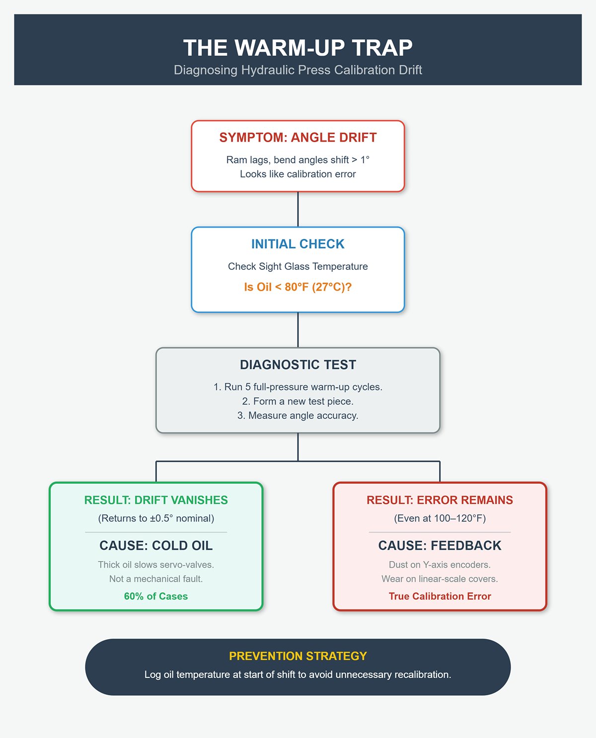
Run five full‑pressure cycles, then form a new test piece. If the angle returns to nominal within about ±0.5°, the drift was caused by temperature, not calibration. If the error remains even after the oil is warm, the issue is in the position feedback—often tiny dust particles on the Y‑axis encoders or wear on the linear‑scale covers, either of which can introduce ±0.01 mm reading errors. Shops that started logging oil temperature at the start of each shift found that six out of ten “calibration problems” were nothing more than cold‑start effects. A simple temperature log prevents hours of unnecessary recalibration and eliminates hidden scrap.
True calibration failures usually show up in ram geometry long before the electronics flag them. You can confirm Y1/Y2 parallelism using just a straightedge and a feeler gauge. Bring the ram to top dead center and check across the bed at both ends and at the center, noting any measurable gaps. On precision press brakes, the end‑to‑end difference should stay under 0.5 mm, while heavy industrial machines tolerate up to 2 mm. Repeat the same checks near bottom dead center to verify consistency.
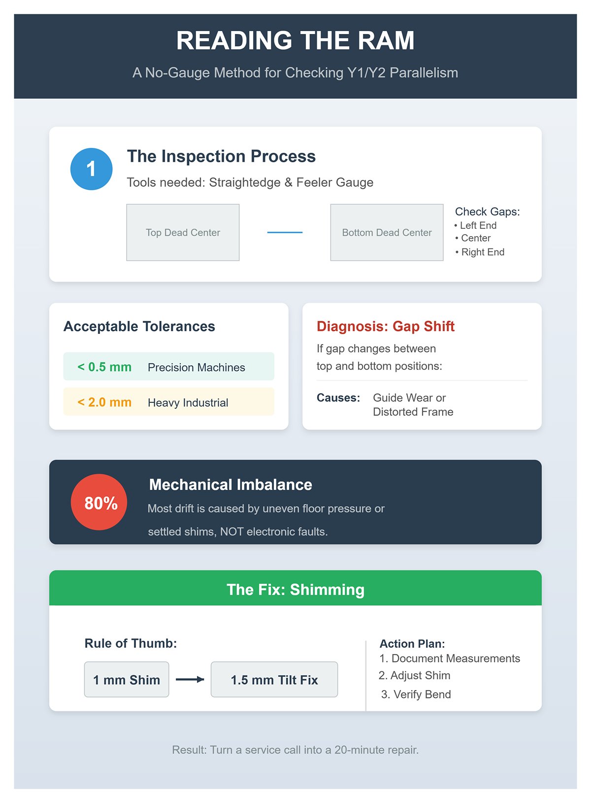
If the gap shifts between top dead center and bottom dead center, it’s a sign of guide wear or a distorted frame—often the result of uneven floor pressure or shims that have settled under a leveling foot. Around 80 percent of inexplicable angle drift originates from this sort of mechanical imbalance rather than electronic faults. The fix is straightforward: add or remove a shim under the appropriate foot. As a rule of thumb, 1 mm of shim can correct roughly 1.5 mm of tilt along the ram. Document your measurements before and after the adjustment, perform a verification bend, and you’ll know whether the issue stems from geometry or the sensors. With this simple check, many operators can turn a “call the technician” situation into a quick, 20‑minute repair.
Your press brake speaks most plainly through sound. A healthy hydraulic pump produces a smooth, consistent hum; any new roughness in that tone is an immediate clue worth investigating. Grinding or scraping suggests metal‑on‑metal contact—likely internal wear in the pump or cylinders shedding tiny fragments. Check the suction filter: if it sparkles, contamination control has failed and the filter needs urgent replacement to avoid total pump seizure.
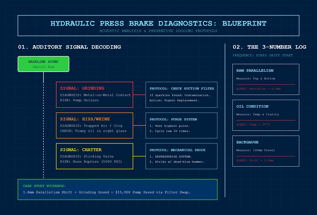
A sharp hiss or thin whine usually indicates trapped air or a clogged suction screen. Foamy oil visible through the sight glass confirms the diagnosis. Vent the highest point, cycle the ram ten times, and the vibration should fade once the air is purged. Chatter or knocking under pressure is more complex—often caused by a sticking proportional‑valve spool or a gummed‑up relief valve. A careful strike with a dead‑blow hammer—only when the system is depressurized—can free the spool and verify the issue. Ignoring these sounds risks dangerous pressure spikes that could rupture hoses rated for 5 000 PSI.
Maintaining a simple “three‑number” log each shift turns gut instincts into preventive care. Every morning, record ram parallelism readings at both top and bottom, oil temperature and clarity, plus backgauge repeatability over a 100 mm travel. Deviations beyond 0.5 mm, oil cooler than 80 °F, or backgauge drift over 0.2 mm signal trouble long before it becomes visible. In one case study, a 1.8 mm parallelism shift accompanied by new grinding noise prompted a team to swap a failing suction filter, saving a $15 000 pump from certain failure—clear evidence that attentive listening and consistent logging outperform reactive fixes.
Those bends that stray off-line aren’t random quirks—they’re messages written in temperature shifts, geometry changes, and sound cues, all telling you what’s altered since the start of the day. Once you know how to interpret them, “drift” stops being a puzzling flaw and instead becomes your press brake’s earliest and most reliable warning signal.
Many press brake manuals dwell on oil level checks and calibration, yet in reality, most issues that halt production originate deeper within the hydraulic system—valves running hot, coils weakening, and microscopic leaks bleeding off pressure long before a visible puddle appears. The technicians who consistently maintain uptime above 95% zero in on three essentials: how valves perform during directional changes, how the oil temperature behaves under actual workload (beyond warm‑up), and whether the system maintains full pressure without cracking open a single manifold bolt.
Jerky or sluggish reversals almost always trace back to a slow‑moving valve spool or a solenoid coil that’s lost power. A solenoid works as an electromagnet moving a plunger to shift the hydraulic spool; when debris or hardened deposits increase friction, the spool can pause for just a fraction of a second. At the ram, that delay appears as hesitation, a visible shake, or a double bump during reversal.
The chief suspect is contamination. Oil that’s gone unfiltered or aged accumulates enough particles within 500–1000 operating hours to hamper plunger movement. Slice open a used return filter and its contents tell the tale: bright metallic specks signal spool wear, while darker residue points to varnish buildup. Either finding is your cue to immediately measure coil voltage. A 24‑volt DC coil reading below 90% of spec won’t produce sufficient magnetic force to reliably snap the plunger—especially with heat stress on the machine. Coils running on borderline voltage routinely lead to scrapping 10–20 parts per hour in high‑volume operations.
One proven field trick from heavy‑duty plants in Germany and Vietnam: while cycling the machine with no load, tap the valve body gently with a dead‑blow hammer. If the spool moves freely afterward, you’ve confirmed it was sticking—no disassembly needed. While this only offers a temporary reprieve and is a clear signal the valve needs thorough cleaning or replacement at the next planned downtime, it restores smooth change‑over in about 80% of cases.
The key mindset shift for operators is simple: when change‑over starts to feel rough or sluggish, check the solenoid first rather than the entire hydraulic system. Most so‑called mysterious hesitation comes from a sticking spool—an early signal that contamination has overtaken the filtration system.
Once oil temperature climbs past 140°F (60°C), the press brake enters a zone where seal materials start losing elasticity—typically 20–30% within roughly 100 hours. As elasticity drops, controlled clearances widen, triggering internal bypass inside cylinders and valves. The operator experiences this as pressure instability: a 15–25% loss at the workpiece even though pump and relief settings remain unchanged.
Heat spikes seldom stem from pump wear; far more often, they trace back to restricted cooling. Clogged heat‑exchanger fins or poorly maintained air coolers account for nearly 30% of unexpected “pump failure” reports in service logs. Operators who record oil temperature at the start of each shift can spot these rising trends long before the machine issues an alarm. A simple routine—weekly fin cleaning and verifying cooler operation at temperature—reduces seal replacements by roughly one‑third in audited facilities.
Crossing 140°F isn’t a minor drift; it’s a critical line. Beyond this point, seals become brittle, varnish builds faster, and the risk of cavitation increases. Keeping oil temperature in check protects every downstream component—especially valves already prone to sticking.
Pressure loss doesn’t always present as dripping fittings or visible puddles. Micro‑leaks within or around manifolds typically bleed 0.5–2 bar per hour—enough to disrupt bending accuracy while leaving no obvious external trace. The warning signs show up in the pressure trend, not on the shop floor.
A simple, tool‑free technique works well during diagnostics: run unloaded cycles at 50% pressure and wrap paper towels tightly around fittings and hose junctions. Fresh hydraulic oil leaves clear stains, exposing “weepers” caused by O‑ring extrusion. These small leaks are extremely common on machines five years or older, especially where hoses bend close to their minimum radius.
If pressure loss continues despite fittings remaining dry, the culprit may be hidden in contamination or water intrusion. Cloudy or frothy oil inside the suction filter chamber is a classic sign of cavitation—responsible for as much as 80% of those “invisible” losses. Often, simply replacing a clogged suction filter and then bleeding trapped air from the system’s high points will restore full pressure within minutes, all without the need to dismantle the manifold.
One of the easiest safeguards is to keep a daily three‑figure record: oil temperature, percentage of pressure retained, and change‑over smoothness time. If you see pressure drop more than 5% from the set point—say, from a 250‑bar relief setting—it’s a clear early warning of leakage or bypassing, well before scrap accumulates or components fail.
By treating valve performance, temperature stability, and pressure integrity as parts of a single, interdependent system—rather than isolated problems—operators can maintain smooth cycle transitions, reliable pressure, and keep costly breakdowns off the calendar.
Many maintenance manuals bury backgauge troubleshooting among lengthy overhaul routines. In reality, about 80% of alignment and precision issues can be spotted—and roughly half corrected—within five minutes if approached methodically. The press brake’s backgauge merges mechanical rigidity, drive integrity, and electronic feedback. The following steps restore that coordination before production quality starts to slip.
A slight looseness in the backgauge finger—so small it’s almost invisible—can easily be mistaken for encoder glitches or drive noise. Begin with a quick 30‑second safety check: lock out power, isolate the hydraulics, and ensure the emergency stop is engaged. With the gauge powered down, conduct a gentle mechanical check by pushing and pulling each finger sideways. Any play exceeding 0.5 mm points to worn splines, under‑torqued clamps, or a sagging rail.
From there, tighten the components that preserve the system’s geometry. On belt‑driven X or R axes, press on the belt midway between pulleys—if it produces a dull flutter, it’s too loose; a crisp, even “thump” signals proper tension. Adjust until the deflection feels firm yet smooth throughout its travel, following the manufacturer’s tolerance range or confirming with a tensiometer. For ballscrew setups, inspect coupling bolts and ensure the encoder connector is fully seated, as even a slight loosening at the coupling can magnify backlash at the finger tip.
Before restoring power, make sure every locking screw on the finger carriage is properly torqued, and apply thread‑locker if they have a history of backing out. Once the machine is energized, run a quick repeatability check: command a 100 mm move out and back three times. If the spread exceeds the job’s allowable tolerance—typically 0.2 to 0.5 mm—you still have a mechanical issue undermining accuracy. The takeaway is simple: a slightly loose finger often masquerades as encoder drift. Secure the finger first, and most mysterious position errors vanish on their own.
Gibs—long bearing strips that keep the backgauge rail aligned—tend to drift out of adjustment gradually, often so slowly that operators adapt without noticing. The result is a gauge that hits target dimensions in the middle of its stroke but wanders at either end, leading to inconsistent flange lengths. Correct gib clearance keeps the carriage square under load while still allowing smooth, unimpeded motion.
With power off, move the carriage to mid‑travel and feel for lateral or vertical play. If movement exceeds about 0.3 mm, the gibs need tightening. Use feeler gauges or a thin shim to check clearance at both ends and the center. Even if only one area feels loose, make adjustments along the entire length; tightening only one section can twist the rail and cause binding.
Turn each gib screw in small increments—about a quarter turn—alternating from one end to the other. Work toward a light, even drag, then back off slightly until the carriage moves freely. After adjusting, home the axis and repeat the 100 mm travel test. When the gibs are set correctly, repeatability tightens immediately, often to better than 0.2 mm, and any load‑induced finger tilt disappears.
Fine‑tuning matters: overly tight gibs generate heat, accelerate wear, and hide true play until the machine cools and loosens again. Gaps that are too loose shift the load path through the frame, allowing the ram to tilt slightly even when hydraulics are functioning perfectly. As one veteran technician put it, “You end up chasing problems hydraulics can’t fix.” Once the gibs are dialed in, the backgauge and ram behave as a single rigid assembly, preserving accuracy even during heavy‑gauge work.
Once the mechanical alignment checks out, the electronic calibration finally has meaning. Running the control’s home or zero‑set routine before securing all hardware is like trying to balance a wheel on a loose hub—it’ll seem right only until the slack shifts again.
Start by homing the gauge once. If the axis returns smoothly but stops consistently a bit short or long, accept that new zero point and test for repeatability. Consistency signals that the mechanics have settled. However, if the gauge sometimes overshoots, hesitates, or drifts—the telltale “ghost move”—follow the signal path. Check the encoder cable and connector; vibration and coolant mist often find their way under the housing. Clean the pins, reseat the plug, and secure the harness so it can’t move with each stroke. While jogging the axis, watch the encoder count screen: random spikes or frozen readings point to a sensor failure or a cracked coupling.
A loose finger clamp can mimic an encoder fault because each impact alters the load torque, which the servo interprets as an outside disturbance. Tighten the clamp, and the supposed “electrical” issue disappears. Don’t call in the electronics technician until every mechanical joint is verified tight and sealed—the machine’s rigidity is the first and most reliable diagnostic tool.
Case 1: A 3 m press brake producing inconsistent flange lengths on 3 mm stainless steel showed a 1 mm spread in gauge return. The operator suspected a servo issue. Mechanical inspection uncovered a single loosened finger spline key. Retightening the clamp reduced the variation to 0.15 mm—no electronic adjustment required.
Case 2: A high‑speed cell presented random homing errors. Closer inspection found uneven gib tension twisting the carriage; as the rail flexed, the encoder reading drifted. Once the gibs were evenly balanced and parallelism restored, the ghost moves vanished.
In just five disciplined minutes—lockout, test, tighten, recalibrate—the operator can turn a fragile alignment into a robust feedback loop. The press brake regains its dependable repeatability, and production goes back to making parts instead of hunting down phantom faults.
Press brakes rarely experience genuinely “random” electrical issues. More often, such faults stem from residual energy trapped in safety or control circuits due to improper shutdown procedures. The most commonly missed step is engaging all emergency-stop (E-stop) buttons—not just the one on the front panel. Any E-stop left unpressed keeps part of the safety loop energized, which can stop the PLC from fully resetting its control state. Leftover voltage in the safety circuit or stored capacitor charge can simulate phantom signals that repeatedly trigger false fault codes.
Experienced field technicians use a precise shutdown and restart sequence to guarantee a complete, clean reboot:
Skipping the idle warm-up and purge process leaves air trapped in the hydraulic lines, causing sluggish solenoid actuation that mimics electrical malfunctions. In one recorded instance, a shop lost four hours of production troubleshooting what they believed was a “PLC lockup.” The issue was resolved when a technician finally pressed an unmarked rear E-stop, completing the safety loop. Ten minutes later, the machine was operational—no service call required.
Press brakes generate high-frequency vibrations—especially during heavy-load bending—that gradually loosen electrical connections, even those with locking tabs. The most frequent problem areas include:
The most effective time to perform an inspection is right after cleaning. Lightly run your fingertip along the DIN rails and adjoining frame areas—any dents or scratches mark spots where high vibration is being transferred. Over time, that vibration tends to loosen Deutsch connectors on encoder lines and limit switches. Give priority to checking and retightening in these specific areas:
Tighten all connections to the manufacturer’s specifications—often around 1–2 Nm for small PLC terminals—and apply dielectric grease to guard against oxidation. Cutting open the hydraulic return filter can help detect metallic particles, a sign that vibration-loosened components are grinding against their housings.
A less obvious but damaging cause of wiring stress is improper frame leveling. When the press brake’s frame is twisted, cable looms slowly stretch, eventually causing crimp connections to fail over months of use. Check frame alignment every quarter using a laser or machinist’s level, and shim the feet if slope exceeds 1 mm per 3 m span. This not only protects wiring but also prevents crowning distortion during bending operations.
For a quick check: move machine axes slowly while gently pulling on suspect wiring at the three points listed above. If you notice any hesitation or trigger a fault, it’s a clear indicator of vibration-related looseness.
Even with wiring in perfect condition, recurring “random” faults often stem from key PLC or drive parameters drifting from their original values—typically due to prolonged vibration, shifts in temperature, or encoder backlash. The settings most worth verifying include:
Use the machine’s diagnostics or advanced parameter menu to verify these values. Jog the ram fully up and down, then measure the height difference across the bed. If the variance exceeds 0.5–2 mm (depending on the press brake class), recalibration is required. Each day, record three key readings:
A clogged hydraulic filter can mimic parameter drift by slowing system response, so replace filters once the pressure drop exceeds specifications. Even if the oil looks clean, operating above 140°F accelerates seal wear and disrupts valve timing. Allow the system a ten‑minute cooldown before resuming heavy operations to stabilize viscosity and ensure consistent parameter readings.
One fabrication shop avoided $2,000 in scrap losses after detecting a slow drift in the backgauge home offset during a 500‑part run. A quick PLC reset corrected the issue and cleared persistent error codes—without the need for expensive component replacement.
Would you like me to draft section 5 as well, so the reader transitions naturally into the next phase of the article? This continuity would help the maintenance procedure flow seamlessly.
Most maintenance manuals concentrate on keeping a press brake operational. The more costly reality, however, is that geometry—not uptime—determines part accuracy and long‑term machine value. Surprisingly, permanent frame and bed deformation seldom result from one‑time overloads. Instead, they stem from small, repeated actions: bending short parts in the same area, neglecting lubrication over multiple shifts, or allowing tooling surfaces to collect debris. The loss of geometry builds gradually, remains invisible at first, and becomes extremely expensive to correct later. This section highlights the three practices that matter most.
Bed and frame deformation typically begins with short‑piece work. When operators bend narrow parts—typically 150–250 mm wide—and consistently place them at the machine’s center for convenience, the load concentrates in a single zone instead of distributing evenly along the bed. This creates an unbalanced moment that the crowning system cannot fully counteract. Both hydraulic and mechanical crowning have design limits, and localized center loading can push those limits by up to 40%.
The impact is tangible: permanent bed deflection of roughly 0.1–0.2mm. It may seem minor, but that deviation is enough to push bend angles out of tolerance and force the crowning system to work beyond its intended range. One Vietnamese appliance plant documented how daily center‑loading of 200mm parts led to actuator binding within six months—resulting in a $15,000 frame realignment and several weeks of lost production.
Two straightforward preventive measures can completely change the outcome:
A quick diagnostic method uses test blocks placed at 25%, 50%, and 75% of the bed length. If the measured deflection between those contact points exceeds 0.05mm, recalibrate the crowning curve or install temporary mechanical wedges before processing additional small‑part runs.
Loss of geometric accuracy often starts with overlooked lubrication failures. The ram guide rails and gib blocks are typically the first areas to show dry zones. Once lubrication has been absent for 50 hours or more, metal‑on‑metal galling begins, increasing friction by up to five times. This is the underlying cause of roughly 30% of ram‑tilt irregularities—even when the hydraulic and electrical systems appear fault‑free.
Early warnings are available if you know where to look. Used hydraulic suction filters often reveal shiny metal flakes—an early indicator of guide wear that surfaces two to three weeks before scoring becomes visible. Detecting these flakes gives you time to reinforce lubrication and correct load patterns before the ram binds, drags, or shifts unexpectedly.
Hidden high‑risk areas include:
Keeping a weekly lubrication log—and consistently applying just 5–10 grams of grease per fitting—can dramatically stabilize performance. A German fabrication plant cut guide wear by 70% simply by recording both grease quantity and intervals. This simple discipline prevented hydraulic pump overloads and eliminated ram unevenness that operators had previously attributed to electronic faults.
Even with a straight frame and well‑maintained guides, geometry can be compromised at the tool interface. “Upset” surfaces—tiny raised spots caused by embedded grit—form high points that make the punch or die rock under load. The result is a gradual bend‑angle drift of 0.02 to 0.1 mm every hundred cycles, a creeping error that looks like ram misalignment and often sends technicians chasing phantom encoder or PLC faults.
The quickest inspection method is tactile: drag your fingernail along the seating surface. Any catching sensation signals roughness above about Ra 3.2 micrometers—enough to shift tool seating. One major automotive supplier traced a 25% spike in scrap to upset surfaces and solved it by wiping seats once per shift with non‑woven cloth. Never use steel wool; it sheds metal particles that embed deeper into the bed.
Two simple habits help keep the tool seat geometry consistent:
At one Mexican plant that kept chasing recurring “PLC errors,” the real culprit turned out to be tool rocking from upset surfaces, which caused minute ram tilts and encoder misreads. A thorough scraping and cleaning of the tool seat eliminated the fault—and thousands of dollars in hourly downtime.
Safeguarding press brake geometry rarely depends on preventing catastrophic failures. It’s about minimizing the subtle, cumulative stresses that slowly distort accuracy. Tackling these small issues protects precision, extends equipment life, and wards off the kind of bed deformation that calibration alone can never correct.
The silent enemy of hydraulic press brakes isn’t excess load—it’s the residual pressure left overnight. Even holding the ram just a few inches above Bottom Dead Center keeps the cylinder seals stretched under static stress for hours, right when cooling oil contracts and intensifies that stress. This contraction magnifies the seal tension. Data from shops monitoring failure rates showed a 70% spike in seal wear when operators failed to park at BDC. The remedy takes just 20 seconds: jog the ram down to BDC, open the dump valve to completely bleed off hold-down pressure, and confirm the gauge reads zero. Zero pressure means zero strain. Teams that make this standard practice routinely see seal life double. One shop plagued by a year’s worth of repeated seal replacements switched to a strict BDC-at-shift’s-end routine and recorded no failures at all the following year.
Once you make this an end-of-day habit, you’ll understand why mornings feel more consistent. With the ram parked at BDC, it no longer drifts during downtime—your first bend lands exactly where the controller predicts. That’s not luck; it’s the result of a system that spent the night in true hydraulic rest.
Most unexplained drift isn’t due to hydraulics—it’s dirt masquerading as mechanical trouble. Linear scales, side guide rails, ram guides, backgauge rails, and tooling seats all trap fine metal dust. Under load, that grit wedges in place, causing ram tilt, backgauge slop, and phantom encoder movements. In fact, 80% of next‑day ram drift comes from contamination on precisely these five components. The fix is straightforward: use a dry, lint‑free cloth—never solvent, which draws dust inward—and wipe these surfaces at the end of each shift. Pay particular attention to the hidden zones: the underside of linear scales, inside corners of guide rails, and shallow ledges where chips settle and cling.
One operator cleared a rail after spotting a 1.2 mm backlash, solving the problem in under two minutes—just as the supervisor was reaching for the service technician’s number. That quick wipe prevented an hour of downtime and avoided a service call altogether. Shops that take weekly before‑and‑after photos see scrap drop by nearly half—less due to cleaner surfaces, and more because the images reveal recurring grit traps, enabling targeted, more effective cleaning.
Operators often remember the moment they realized a single speck of grit could throw off a bend by 2 mm. The smallest contaminants can spark the biggest troubleshooting chases.
Nothing will compromise a well-running machine faster than allowing each shift to “correct” the previous one. This kind of offset tinkering is behind roughly 65% of inconsistent results at the start of the day. The fix is a disciplined hand-off: a concise script that states exactly what condition the machine is in and the key numbers that confirm it. The script is straightforward:
Logging these three measurements catches most issues before they turn into scrap. One shop even printed the checklist on a laminated card. Their shift-change mistakes went from three per week to zero. On one occasion, an afternoon operator spotted a 1.8 mm drift; the log required verification before altering offsets. They discovered grit on the rail, cleaned it, re-measured, and the overnight run proceeded flawlessly.
The true value of this script lies in its psychology. It communicates to the next shift: “The machine was accurate when I left. If it isn’t now, measure before you adjust.” That clear boundary safeguards your machine’s precision.
Operators often recall the opening image: the press brake that seems to wake up “in a bad mood,” misaligning the very first bend and wasting the first hour. This end-of-shift ritual is the cure for that disorder. Parking at BDC relieves hidden pressure. Wiping down removes unseen grit. And the hand-off stops the stealthy sabotage that can happen between shifts.
The next morning, when your first bend is perfectly accurate, it won’t feel like luck—it will feel like the result of deliberate care.


