

Last Tuesday you bent ten brackets out of 1/8″ A36. First one read 90°. Second one 91.5°. By the eighth, you were staring at 93° and cranking the ram down another .010″ like that would scare the steel into behaving.
You weren’t shaping metal.
You were picking a fight with it.
Stand in front of a press brake long enough and it starts to look like a stamp. Punch comes down. Die sits there at 90°. Metal gets squeezed in between. So if the part isn’t 90°, the rookie answer is simple: more tonnage.
I watched a kid run 3/16″ plate into a 1/2″ V-die and dial the pressure up near the machine’s rated limit because the angle kept opening up. He figured if 40 tons didn’t do it, 60 would. By lunchtime the ram was groaning, the tooling was mushroomed on the shoulders, and the parts were still drifting a degree and a half. That tooling set cost more than his pickup. Expensive mistake.
The brake isn’t a mold. It’s a lever. And the steel isn’t clay. It’s a spring.
So what actually happens when you lean on that pedal and try to crush the problem flat?
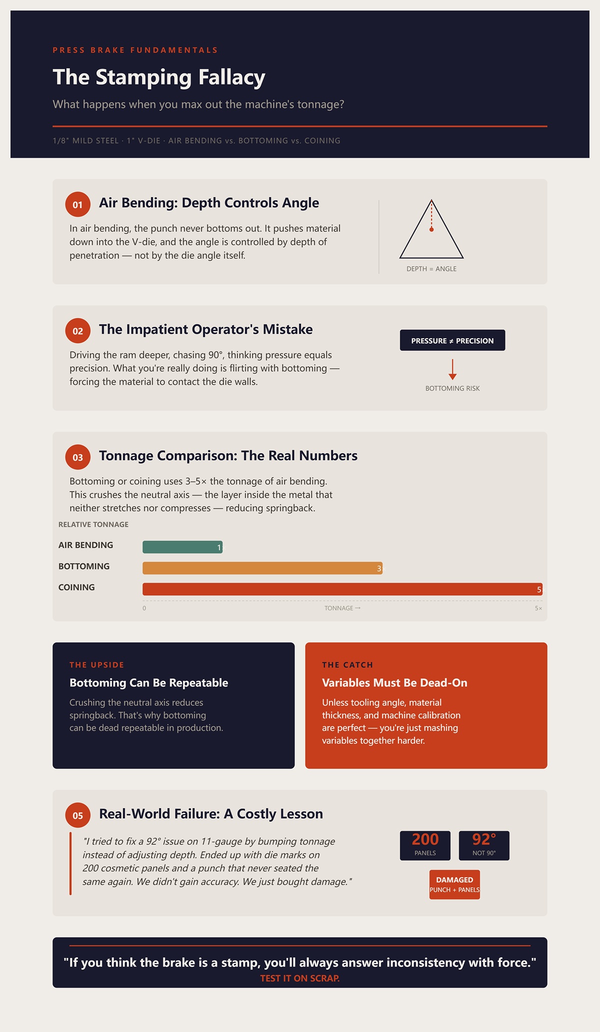
Let’s say you’ve got 1/8″ mild steel in a 1″ V-die. In air bending, the punch never bottoms out. It pushes the material down into the V, and the angle is controlled by how deep you go — not by the die angle itself.
Now you get impatient. You drive the ram deeper, chasing 90°, thinking pressure equals precision. What you’re really doing is flirting with bottoming — forcing the material to contact the die walls.
When you bottom or coin, you’re using 3–5 times the tonnage of air bending. That crushes the neutral axis — the layer inside the metal that neither stretches nor compresses — and it does reduce springback. That’s why bottoming can be dead repeatable in production.
But here’s the catch: unless your tooling angle, material thickness, and machine calibration are dead-on, you’re just mashing variables together harder.
I once tried to “fix” a 92° issue on 11-gauge by bumping tonnage instead of adjusting depth. Ended up with slight die marks on 200 cosmetic panels and a punch that never quite seated the same again. We didn’t gain accuracy. We just bought damage.
If you think the brake is a stamp, you’ll always answer inconsistency with force.
Test it on scrap.
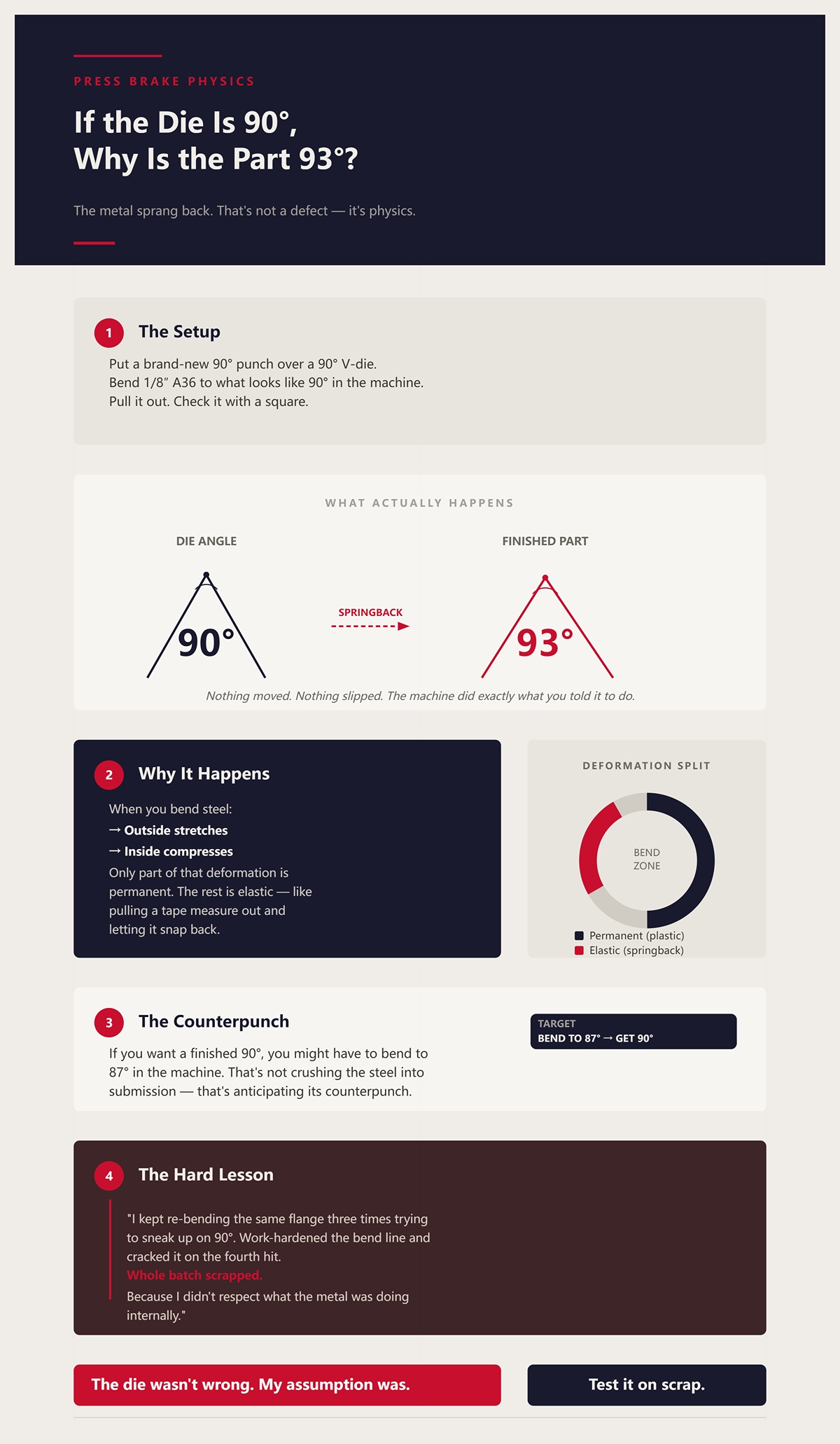
Put a brand-new 90° punch over a 90° V-die. Bend 1/8″ A36 to what looks like 90° in the machine. Pull it out. Check it with a square.
It reads 93°.
Nothing moved. Nothing slipped. The machine did exactly what you told it to do.
The metal sprang back.
When you bend steel, the outside of the bend stretches. The inside compresses. Only part of that deformation is permanent. The rest is elastic — like pulling a tape measure out and letting it snap back. When the ram comes up, the elastic portion releases, and the angle opens.
That’s springback. And it’s not a defect. It’s physics.
If you want a finished 90°, you might have to bend to 87° in the machine. That’s not crushing the steel into submission. That’s anticipating its counterpunch.
The first time I learned this, I kept re-bending the same flange three times trying to “sneak up” on 90°. Work-hardened the bend line and cracked it on the fourth hit. Whole batch scrapped because I didn’t respect what the metal was doing internally.
The die wasn’t wrong. My assumption was.
Test it on scrap.
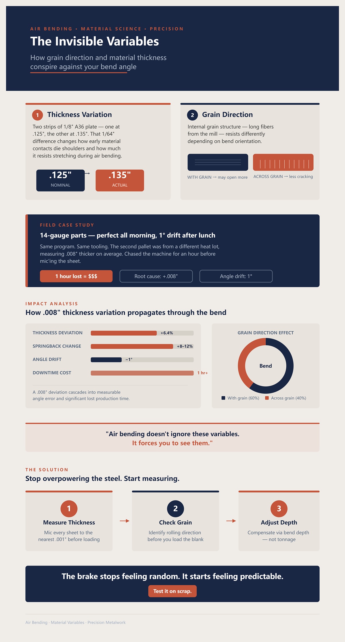
Take two strips of 1/8″ plate, both labeled A36. One measures .125″. The other is .135″. That 1/64″ difference doesn’t look like much until you’re air bending.
Air bending angle is controlled by penetration depth into the V. Thickness changes how early the material contacts the die shoulders and how much it resists stretching. A thicker sheet will spring back differently than a thinner one, even if the program is identical.
Now rotate the blank 90° so you’re bending across the rolling grain instead of with it. The internal grain structure — long fibers from the mill — resists differently depending on direction. Across the grain, you often get less cracking but slightly different springback. With the grain, it may open more.
I once ran 14-gauge parts that were perfect all morning. After lunch, angles drifted 1°. Same program. Same tooling. Turned out the second pallet was from a different heat lot, measuring .008″ thicker on average. We chased the machine for an hour before we mic’d the sheet. That hour cost more than the material.
Air bending doesn’t ignore these variables. It forces you to see them.
If you stop trying to overpower the steel and start measuring thickness to the nearest .001″, checking grain direction before you load the blank, and adjusting bend depth instead of tonnage, the brake stops feeling random.
It starts feeling predictable.
Test it on scrap.
You bend a strip of 1/8″ A36 to 87° in the machine. Gauge says 87.2°. You let the ram up, pull the part, set a square on it.
It reads 90° dead.
Nothing magical happened in that half-second. No ghosts in the hydraulics. What happened was strain recovery — the elastic portion of the bend letting go. And it started happening before you ever released the pedal.
Here’s the part most rookies miss: the bend isn’t either “temporary” or “permanent.” It’s both at the same time, stacked through the thickness. The outer skin is stretching past yield. The inner skin is compressing. Somewhere between them is a thin layer that hasn’t yielded yet. That layer is already trying to pull the bend back open while you’re still pushing down.
That pullback is the tax you pay for bending. You don’t eliminate it. You budget for it.
So at what exact point does the metal stop negotiating and start obeying?
Take that same 1/8″ strip. Mild steel like A36 yields around 36,000 psi. Below that stress, it behaves elastically — meaning strain is proportional to stress, and when you unload it, it returns to its original shape. Like a spring. Go past yield, and the crystal structure slips. That slip is plastic deformation. That part stays.
When you start the bend, the entire thickness is elastic. As the punch drives deeper into the V, the outer fibers — the farthest from the neutral axis — see the highest tension. They hit yield first. Plastic zone starts at the outside and works inward as curvature increases.
The bend becomes “permanent” the moment any fiber passes yield. But it becomes usefully permanent only when enough of the thickness has yielded that the remaining elastic core can’t pull it all the way back flat.
Picture the cross-section: outer 1/32″ yielded, inner 1/32″ yielded in compression, and a thin elastic core in the middle. When you release the load, that elastic core unloads and redistributes stress. That’s why the angle opens.
I scrapped a run of 3/32″ stainless once because I kept tapping the pedal, trying to “sneak up” on 90° in four light hits instead of one controlled overbend. Each hit added plastic strain at the surface but left a stubborn elastic core. By the fourth hit, the outer fibers were work-hardened and brittle. Hairline cracks along 50 parts. That job paid for my lesson.
If you want to see this for yourself, bend a coupon to 45°, release it, then rebend it slightly deeper and watch how much less it springs back the second time. You’ve increased the plastic zone thickness. The elastic core got thinner.
Cut a 2″ × 6″ strip and try it. Measure before and after each hit. Test it on scrap.
Now why does 1/4″ steel feel more honest than .050″ aluminum, even when both are cut clean and bent in the same brake?
Run 1/4″ A36 in a 2″ V-die. Overbend it to 88° in the machine. It might spring back 1°.
Now run .050″ 5052 aluminum in a 1/2″ V-die. Overbend to 85°. It might spring back 3° or more.
Two things are happening.
First, thickness. Springback is roughly proportional to the ratio of elastic strain to total strain. Thicker material, bent in a properly sized V (about 8× thickness for steel as a starting point), develops a larger plastic zone relative to its thickness. More of the cross-section has yielded. The elastic core is a smaller percentage of the whole, so it has less leverage to pull the angle open.
Thin sheet? The plastic zone is shallow. The elastic portion dominates. It lies to you.
Second, modulus and work hardening. Steel has a modulus of elasticity around 29 million psi. Aluminum is closer to 10 million psi. Lower modulus means for the same stress, aluminum strains more elastically. More elastic strain stored. More to recover on release.
And aluminum work-hardens fast. I’ve seen a job where we bent .080″ 5052 brackets, checked them, found we were 2° open, and tried to correct by rebending. After two hits, the bend line stiffened up so much the third correction barely moved it — and the fourth cracked. We had to stop production and anneal a batch in an oven just to finish the order. Steel would’ve tolerated that sequence better.
That’s why thicker steel “lies less.” Not because it’s obedient. Because proportionally, more of it has crossed yield, and its elastic memory isn’t as dominant.
Mic your sheet to the nearest .001″. Check alloy and temper before you assume the same program will work. Bend one coupon from each lift of material and record the springback. Test it on scrap.
So how is all this force actually being applied in the first place?
Look at the setup: punch tip on top, die shoulders left and right. The sheet spans the V like a bridge. When the punch comes down, you’re not crushing the whole flange. You’re creating a three-point bending system — two supports at the die shoulders and a concentrated load at the punch tip.
That means maximum bending moment — the highest internal stress — is right under the punch. Stress decreases toward the die shoulders. It’s not uniform.
During loading, the outer fibers under the punch yield first. As you go deeper, that yielded region spreads. When you release, unloading isn’t uniform either. The elastic strain recovers, but because plastic deformation is inhomogeneous across the radius, stress redistributes. The metal doesn’t just “spring.” It rebalances internally.
That’s why air bending works. You’re controlling curvature by depth in a predictable three-point system. It pushes the material down into the V, and the angle is controlled by how deep you go — not by the die angle itself.
When you bottom or coin, you change the model. Now the sheet contacts the die walls. You’re no longer in pure three-point bending. You’re compressing the entire bend zone, overwhelming the elastic recovery. Springback drops because you’ve driven nearly the full thickness past yield. That’s why coining can almost eliminate the springback tax — at the cost of 3× to 5× the tonnage and tighter tooling tolerances.
Different physics. Different bill.
Set up a simple test: bend a 3″ wide coupon in air, record angle. Then bottom the same thickness in the same die with higher tonnage and compare springback. Feel the difference in pedal pressure. Measure the angle shift after release. Test it on scrap.
Once you see bending as three-point loading with a layered elastic-plastic cross-section, springback stops being an insult.
It becomes a number you plan for.
And that’s where air bending stops looking like a compromise — and starts looking like control.
You’ve got 1/8″ A36 in an 8× thickness setup — that’s a 1″ V-die. You need 90° finished. First one read 90°. Second one read 91.5°. Third one 89°. Same program. Same machine. So how do you predict the overbend instead of chasing it part to part?
You start by accepting this: in air bending, the die angle is almost irrelevant. The punch never drives the sheet into full contact with the die walls. You’re floating between the shoulders. That means the only hard control you’ve got is depth — how far the punch penetrates into the V. It pushes the material down into the V, and the angle is controlled by how deep you go — not by the die angle itself.
That’s the loophole.
If depth controls angle, then angle is a function of punch penetration minus springback. And springback is a function of material, thickness, grain direction, and inside radius. So the real question becomes: how does that floating geometry translate into a number you can dial in?
Picture a 90° V-die. You bring the punch down until the part measures 88° under load. You release. It opens to 90°. That 2° was elastic recovery.
Now change nothing except depth. Go .010″ deeper. Under load it reads 86.5°. Release. Now it springs to 89°.
What changed? Not the die angle. Not the punch angle. Only penetration.
In air bending, the inside radius forms naturally as roughly 16% of the V-opening for mild steel in a proper 8× setup. So in a 1″ V, you’re getting about a .160″ inside radius whether you like it or not. That radius determines how much of the thickness yields. That yield depth determines the elastic core thickness. That elastic core determines springback.
So your control knob is penetration depth, which changes bend angle, which changes how much of the cross-section crosses yield.
Years back, a kid on second shift swapped a 1″ V for a 3/4″ V because “it looked close enough.” Inside radius dropped. Plastic zone increased. Springback dropped almost 1°. He didn’t change the program. We scrapped 60 brackets before we figured out the die was wrong. Die width changed radius. Radius changed springback. Expensive lesson.
Here’s how you dial it in properly:
Then test it on scrap.
So if depth is king, why not just drive it harder and eliminate the guesswork?
Take two sheets of 11-gauge. One mics .119″. The other .123″. Four thousandths difference. Doesn’t look like much.
In air bending, that thickness change slightly shifts the neutral axis — that imaginary layer that doesn’t stretch or compress. Thicker sheet means a slightly larger inside radius forms for the same V. That changes springback by maybe half a degree.
But because you’re only making three points of contact — punch tip and die shoulders — the system flexes with the material. The angle changes mostly by depth, not by crushing thickness into a fixed cavity. The variation shows up as a small angle difference you can trim with a depth tweak.
Now imagine bottoming the same sheets.
What you’re really doing is flirting with bottoming — forcing the material to contact the die walls. Now thickness variation has nowhere to go. That extra .004″ gets compressed between steel tools rated harder than the part. Tonnage spikes. Angles swing. Tooling wears. Parts mark.
I once saw a shop coin 14-gauge cosmetic panels because they were tired of “chasing springback.” They eliminated 1° of variation and added die marks to 200 visible faces. The customer rejected the lot. They solved angle drift and created a finish disaster.
Air bending would’ve absorbed that thickness spread. A 0.5° swing is cheaper than refinishing 200 panels.
Here’s the discipline:
Then test it on scrap.
If less force gives you flexibility, where’s the line before you lose authority over the bend?
Look at your tonnage chart. For 1/8″ A36 in a 1″ V, air bending might call for roughly 12–15 tons per foot. Bottoming that same setup could demand double or triple.
If your brake reads 30 tons per foot on that job, you’re not air bending anymore. You’re transitioning into bottoming whether you planned to or not. Springback drops — sure. But now the inside radius is being forced smaller than the natural air-bend radius. The entire thickness is being driven closer to yield. That means less elastic core. That means less forgiveness.
Control turns into dependency. Now angle depends on exact thickness and exact die geometry.
On older manual brakes without CNC depth repeatability, this is where beginners get burned. They think more pressure equals more consistency. In reality, they’ve removed the floating cushion that air bending gives them. Any ram variation, any deflection in the frame, any grain-direction shift shows up directly in the part.
The sweet spot is this:
Enough penetration to achieve the angle plus planned overbend. Enough tonnage to form the natural inside radius. Not enough to force full die contact.
Watch the tonnage gauge during the stroke. If it climbs sharply at the bottom of travel, you’re likely hitting the die walls. Back off depth a few thousandths and remeasure.
Then run three consecutive coupons and compare angles after full unload. If they repeat within your tolerance, lock it in.
And test it on scrap.
Because once you understand that punch depth — not brute force — decides your finished angle, the next thing you should be asking is this:
How precise does your setup need to be if thousandths of depth are steering degrees of angle?
Last month we bent 1/8″ A36 in a 1″ V to 93° so it would spring back to 90°. First one read 90°. Second one read 91.2°. Nothing changed in the program. What changed was the setup: the sheet was .006″ thicker at the far end, and the ram was out of parallel by maybe .002″ over 6′. That’s all it takes. Thousandths in depth turn into whole degrees at the part.
You already know penetration depth is the steering wheel. Now we make sure the steering linkage isn’t sloppy.
Start with the machine. Check ram parallelism with a pair of ground blocks and a feeler gauge. If you can slip a .003″ feeler on one side and not the other at bottom of stroke, you’ll chase angle all day. That’s where crowning comes in — mechanical or hydraulic compensation to counteract frame deflection under load. Without it, the center bends 89° while the ends read 91°. I watched a shop scrap 40 architectural rails because nobody checked deflection after a 20‑ton job earlier in the shift warmed the frame. The brake grew just enough to lie to them.
Dial in parallel. Verify crowning against a full‑length test strip. Then test it on scrap.
Once the machine is honest, tooling geometry is next. That’s where most beginners gamble without realizing it.
Grab a micrometer. Measure your sheet. Let’s say it’s .125″ on the nose. Multiply by 8. That gives you a 1.000″ V-opening for mild steel. Not 7× because it’s “close.” Not 10× because it’s “what’s in the rack.” Eight times thickness is the starting line because it balances three things: inside radius formation, required tonnage, and springback predictability.
In a true 8× setup on mild steel, your inside radius will land around 16% of the V-opening. In a 1″ V, that’s about a .160″ inside radius. That radius defines how much of the cross-section yields. Change the V to 3/4″ and your natural radius shrinks to roughly .120″. Smaller radius means more plastic deformation. More plastic deformation means less springback — and more tonnage.
I once saw a guy squeeze 3/16″ plate in a 1″ V because it “fit.” That’s barely 5.3× thickness. Tonnage spiked past the chart. They cracked a die shoulder clean off. Eight thousand dollars gone because nobody did multiplication.
There’s a qualifier: tight offsets closer than about 6× material thickness can clash with an 8× die. In that case you may step down a V, but you’d better recalc tonnage and expect a different inside radius and springback number. Change one variable, update the math.
Pick the V from thickness, not from convenience. Confirm the math against your tonnage chart. Then test it on scrap.
If the V-opening sets the natural radius, what’s the punch really doing?
Put a sharp punch — say a .030″ tip — over that 1″ V with 1/8″ steel. Beginners think the inside radius will be .030″. It won’t. In air bending, the die width mostly decides the inside radius, not the punch tip, as long as the punch radius is smaller than the natural radius the V wants to create.
That .160″ inside radius we talked about? It forms because the sheet is floating between the shoulders. It pushes the material down into the V, and the angle is controlled by how deep you go — not by the die angle itself. The punch just initiates the bend and concentrates force.
Now swap in a punch with a .200″ radius — larger than the natural .160″. Suddenly the punch is the limiter. The material wraps the punch, and your inside radius grows. Springback changes because your plastic zone changed. Same V. Same thickness. Different result.
I learned that on 3/32″ stainless. We switched to a larger punch radius to prevent surface cracking on a brushed cosmetic part. Inside radius increased by about 1/32″. Springback jumped nearly a degree. Nobody adjusted overbend. We scrapped an entire batch of panels with hairline cracks and wrong angles in the same week.
Match punch radius to be equal to or slightly smaller than the expected natural radius unless the print demands otherwise. If you intentionally change it, adjust your overbend target and tonnage expectation.
Set it up. Run one coupon. Measure inside radius with radius gauges, not your eyeball. Then test it on scrap.
Once geometry is fixed, angle accuracy comes down to one deliberate move: aiming past the target.
Take that 1/8″ A36 in a 1″ V. Typical springback might be 2° in air bending. So if the print calls for 90°, you program for 92°. Maybe 93° depending on grain direction.
Don’t guess. Bend a coupon to 90° under load and let it spring. If it opens to 92°, you know springback is 2°. Now bend to 88° under load so it springs to 90°. That’s aiming through the angle.
What you’re really doing is predicting how much elastic core is left after you release pressure. You’re negotiating with it. If you shove it harder and drift toward bottoming, springback shrinks — but now thickness variation controls your angle instead of depth. That’s how beginners get fooled into thinking brute force is precision.
I watched a new operator chase a 0.5° error by adding pressure instead of depth. He crossed into die contact. Angle looked perfect for five parts. Then the next sheet, .004″ thicker, came out 1.5° tight. He had unknowingly removed the cushion air bending gives you.
Record the actual springback number for that material, thickness, grain direction, and V. Program the overbend intentionally. Then confirm three consecutive parts after full unload.
And yes — test it on scrap.
But all this assumes you’re inside safe tonnage. Miss that, and the rest doesn’t matter.
Open the chart. Find 1/8″ mild steel in a 1″ V. You’ll see roughly 12–15 tons per foot for air bending. On a 4′ part, that’s 48–60 tons total. If your brake is rated at 100 tons over 10′, you’re fine — as long as you’re actually air bending.
Now look at bottoming numbers for the same setup. They can jump to 25–30 tons per foot or more. That’s double. Sometimes triple.
If your tonnage gauge spikes hard at the bottom of stroke, you’re no longer floating between the shoulders. You’re driving the material into the die walls. What you’re really doing is flirting with bottoming — forcing the material to contact the die walls. Tooling sees that load before you do.
We had a 90‑ton press snap a segmented punch because someone assumed “it’s only 11‑gauge.” They didn’t notice the V was undersized and the part was 6′ long. Actual load exceeded tool rating by about 20%. Steel doesn’t care about your assumptions.
Calculate tons per foot. Multiply by bend length. Compare to both machine capacity and tool rating — which are not always the same number. Stay comfortably below bottoming tonnage if the job calls for air bending accuracy.
Set the depth stop based on angle, not force. Watch the gauge for unexpected spikes. Then run your first article and measure.
Because once you can pick the right V, match the punch, aim through springback, and prove the tonnage is safe, you’re no longer crushing metal.
| Section | Content |
|---|---|
| Title | Reading a tonnage chart vs. guessing: The calculation that prevents tool damage |
| Air Bending Reference | Open the chart. Find 1/8″ mild steel in a 1″ V. You’ll see roughly 12–15 tons per foot for air bending. On a 4′ part, that’s 48–60 tons total. If your brake is rated at 100 tons over 10′, you’re fine — as long as you’re actually air bending. |
| Bottoming Comparison | Now look at bottoming numbers for the same setup. They can jump to 25–30 tons per foot or more. That’s double. Sometimes triple. |
| Warning Signs | If your tonnage gauge spikes hard at the bottom of stroke, you’re no longer floating between the shoulders. You’re driving the material into the die walls. What you’re really doing is flirting with bottoming — forcing the material to contact the die walls. Tooling sees that load before you do. |
| Real-World Failure Example | We had a 90‑ton press snap a segmented punch because someone assumed “it’s only 11‑gauge.” They didn’t notice the V was undersized and the part was 6′ long. Actual load exceeded tool rating by about 20%. Steel doesn’t care about your assumptions. |
| Proper Calculation Method | Calculate tons per foot. Multiply by bend length. Compare to both machine capacity and tool rating — which are not always the same number. Stay comfortably below bottoming tonnage if the job calls for air bending accuracy. |
| Setup Best Practices | Set the depth stop based on angle, not force. Watch the gauge for unexpected spikes. Then run your first article and measure. |
| Conclusion | Because once you can pick the right V, match the punch, aim through springback, and prove the tonnage is safe, you’re no longer crushing metal. |
You’re controlling it.
And that’s when you can start asking a smarter question: when does air bending stop being enough?
You’ve done everything right — picked the 1″ V for 1/8″ A36, matched the punch radius, aimed 2° past 90°, confirmed 12–15 tons per foot, and your first one read 90°.
So when does air bending stop being enough?
Not when you’re lazy. When the tolerance gets tighter than the cushion air bending gives you.
Air bending is controlled because penetration depth is the steering wheel. You’re floating between the shoulders, predicting springback, and adjusting by thousandths of ram travel. That flexibility is its strength. But flexibility is also movement, and movement has limits. When the print says ±0.25° on a 36″ flange, you’re no longer negotiating — you’re being audited.
That’s where bottoming and coining come in. Not as upgrades. As trade-offs.
They don’t make you smarter. They just reduce how much thinking the part is allowed to do.
In clean air bending, a .004″ thickness change can shift your angle about half a degree, sometimes more depending on V width and material strength. That’s not sloppiness. That’s geometry.
Because in air bending, angle comes from depth. And depth reacts to thickness.
If your sheet batch varies from .119″ to .123″, your neutral axis — that imaginary line in the cross-section that doesn’t stretch or compress — shifts slightly. That changes how much elastic core is left after unloading. Springback changes. Your programmed 92° under load might spring to 89.5° on one sheet and 90.7° on the next.
Now picture a print calling for 90° ±0.25°. You can dial the ram to within .001″ of repeatability. The brake can be perfect. The math can be right. But the material itself is moving the goalposts.
I watched a kid try to hold ±0.25° on 3/16″ stainless in a 1‑1/4″ V. He kept bumping depth .002″ at a time. Parts walked in and out of tolerance all afternoon. We scrapped 38 brackets before he understood it wasn’t the machine — it was the variability air bending politely tolerates.
When the tolerance band is narrower than the material variation, air bending hits its ceiling.
So what happens if you stop letting depth control everything?
Bottoming means you intentionally drive the punch until the material contacts the die walls. Not crushing it flat — that’s coining — but seating it firmly into the V so the die angle now matters.
You shift control from ram depth to tool geometry.
That’s why an older brake with mediocre depth repeatability can still hold tight angles in bottoming. The die becomes the governor. Once the material fully seats, small thickness changes don’t swing the angle as wildly because the walls constrain it.
But here’s the cost.
Your punch angle, die angle, and material thickness have to match almost exactly. If you’re bending 90° in 1/8″, you need a 90° punch and a 90° die sized for that thickness. Want 88° instead? New die. Different thickness? Probably new die again.
I once swapped from .120″ to .135″ material mid-run and tried to cheat the same bottoming setup. Angles came out 1° open because the thicker sheet couldn’t fully seat without more tonnage. We forced it. Cracked a die shoulder that cost more than the whole job.
Bottoming gives you repeatability by removing flexibility. Great for 1,000 identical parts. Miserable for five parts all at different angles.
So what if even bottoming isn’t tight enough?
Coining is where you stop negotiating and rewrite the material’s memory.
You drive the punch tip into the material with enough force — sometimes 5 to 10 times air bending tonnage — that you plastically compress the inside surface. You’re not just bending anymore. You’re thinning the material at the bend line.
Springback drops close to zero because you’ve yielded almost the entire cross-section.
Angle equals punch angle. Period.
Sounds perfect, right?
Here’s what they don’t tell you: that tonnage spikes fast. Take that same 1/8″ steel that needed roughly 15 tons per foot in air bending. Coining could demand well over 100 tons per foot depending on punch radius and die opening. Your tooling feels every bit of it.
We coined 16‑gauge stainless once for a cosmetic 90° hem that had to sit dead flush. After 600 hits, the punch tip started to mushroom. By 1,200, the angle drifted because the tool geometry changed. The “perfect” method wore itself out mid-run.
And you’ve permanently thinned the bend zone. On structural parts, that matters.
Coining is a scalpel made of a sledgehammer.
So now the real question isn’t which method is most accurate. It’s whether the job justifies the punishment.
Air bending: one V die, multiple angles, minimal setup swaps. You adjust depth and go. Tool life is long because you’re staying below bottoming tonnage.
Bottoming: angle-specific tooling, careful matching, higher load. Setup takes longer. Tool wear increases, but you gain repeatability on large batches.
Coining: maximum load, fastest tool wear, least flexibility — but near-zero springback.
If you’re running 25 brackets at three different angles, air bending wins every time. You’ll spend more time changing bottoming dies than actually bending.
If you’re running 5,000 stainless rails that must hold ±0.25° all day, bottoming may pay for itself in scrap reduction alone.
If you’re making a precision electrical contact where angle must be dead-on and springback cannot exist, coining earns its keep — and you budget for tooling wear like it’s consumable.
Most beginners think bottoming and coining are “more accurate.” They’re not. They’re more restrictive.
Air bending is the default because it lets you control the physics instead of overpowering it. Bottoming and coining are what you reach for when the print, the volume, or the machine forces your hand.
And once you know which method you chose and why, the next skill isn’t picking the process.
It’s reading a bad bend and tracing it back to the variable you missed.
You pull a 36″ long 1/8″ A36 bracket off the brake. Left end reads 90°. Middle reads 91°. Right end reads 88.5°. Same program. Same tools. Same operator.
So what failed — the bed, the tooling, the material, or your method?
Stop blaming the machine for five minutes and look at the part like it’s talking to you. A bend never lies. It tells you where the force went, where the material resisted, and where you lost control of springback. Your job isn’t to crush it straighter. Your job is to read the clues and trace them back to one variable at a time.
That’s how you stay in control of air bending instead of letting it drift on you.
Picture that 36″ bracket again. Ends tight. Center open by 1°.
First question: is the error gradual and centered? That smells like deflection. When you load 12–15 tons per foot bending 1/8″ A36 in a 1″ V, you’re hanging a small bridge worth of force across the bed. The ram and bed bow upward in the middle unless crowning compensates. Less penetration in the center means less overbend, which means more springback there. Open angle in the middle every time.
I watched a shop scrap 40 rails before checking crowning. They kept bumping depth .003″ trying to fix the center. That only overbent the ends. Expensive mistake.
How do you isolate it? Run the same part, same setup, but bend a 6″ coupon in the center of the machine only. Then bend another 6″ coupon near the left side. If the short pieces match but the long one doesn’t, you’re looking at frame deflection. Adjust crowning. Test it on scrap.
Now suppose the angle swings randomly — tight, open, tight — no pattern. That’s usually material thickness variation. Remember when I told you penetration depth is the steering wheel? In air bending, the angle is controlled by how deep you go — not by the die angle itself. If your sheets vary from .119″ to .123″, the neutral axis shifts and the elastic core changes. Springback shifts with it.
I’ve seen a kid chase ±0.25° all afternoon on 3/16″ stainless because he didn’t mic the stack. Four thousandths of thickness cost him 38 parts. Expensive mistake.
Mic three spots across the sheet. If thickness moves, your angle will move unless you compensate depth per sheet or tighten material spec. Test it on scrap.
Last possibility: tooling. If the punch isn’t seated or the die shoulders are worn unevenly, one end can penetrate deeper than the other. Blue up the punch tip with layout dye, make a light hit, and check contact pattern. Uneven witness marks mean setup, not physics. Clean, reseat, re‑clamp. Test it on scrap.
See the pattern? You don’t guess. You isolate.
But what if the angle is right and the metal is splitting?
Take a strip of 3/32″ stainless. Bend it 90° across the grain in a 1/2″ V with a sharp punch radius around 1/32″. You’ll hear it before you see it — that faint tearing sound. Then the hairline crack shows up on the outside surface.
What happened?
When you bend, the inside compresses and the outside stretches. The tighter the inside radius, the more the outside fibers elongate. If your punch radius is smaller than the material can handle, you exceed its elongation limit. Across the grain makes it worse because rolled grain direction already has elongated structure. You’re stretching it the hard way.
I once scrapped a full rack of 3/32″ stainless brackets because we bent perpendicular to grain with too sharp a punch. Print didn’t call out grain. We assumed. That assumption cost a week. Expensive mistake.
Diagnosis is simple. Measure your inside radius. In air bending, inside radius is roughly 16% of the die opening for mild steel. So a 1″ V gives about a .160″ inside radius. Go tighter — say a 1/2″ V — and you’re flirting with bottoming and forcing a smaller radius. What you’re really doing is flirting with bottoming — forcing the material to contact the die walls — and that spikes strain at the surface.
Rotate a blank 90° and bend again. If cracks disappear with grain, you found your culprit. If not, open the V die one size and increase inside radius. Test it on scrap.
Cracks are never random. They’re strain exceeding ductility. Your job is to reduce strain or change direction.
Now what about a part that doesn’t crack and doesn’t vary in angle — it just physically won’t let you make the second bend?
Imagine a channel: 2″ web, 1″ flanges on both sides, 1/8″ thick. You bend one 1″ flange up to 90° in a 1″ V. Clean. Then you flip it to bend the opposite flange.
The already-bent flange hits the punch body before the second bend reaches 90°. You stall at 75°. The machine isn’t weak. The geometry is blocking you.
I watched an apprentice force one like that, thinking tonnage would fix clearance. He drove it harder. Marked the punch shoulder and distorted the first flange. Two ruined parts before we stopped him. Expensive mistake.
The issue isn’t force. It’s sequence and tool clearance. In air bending, the punch has a body width. If the return flange is too close, it collides before full penetration. Remember: it pushes the material down into the V, and the angle is controlled by how deep you go — not by the die angle itself. If you can’t reach depth, you can’t reach angle.
Fix it by bending the farthest flange first, or by using a gooseneck punch with throat clearance. Lay the part against the punch before cycling and physically check for interference. If steel touches steel where it shouldn’t, no amount of tonnage will solve it. Test it on scrap.
Every bad bend falls into a bucket: force distribution, material behavior, or geometry interference. The part tells you which one — if you quit treating the brake like a hammer and start treating the steel like a spring you’re negotiating with.
And once you can read those clues without panic, you stop reacting to bad bends.
You start predicting them.
You want bends that don’t surprise you?
Then stop trying to hit 90°.
Last month we ran 1/8″ A36 in a 1″ V. First one read 90°. Kid smiled. Pulled it out, checked again five minutes later — 91.5°. Steel relaxed. He thought the machine drifted and bumped depth another .010″. Now it came off at 88.5° after springback. Three parts in and we were chasing ghosts.
Expensive mistake.
You are not making a 90° bend. You are bending to 92° so it relaxes back to 90°. That’s the overbend mental model. You don’t fight springback. You plan for it.
And once you accept that, the setup question changes.
Steel is a spring with a yield point. Up to yield, it flexes and returns. Past yield, it stays bent — but the elastic core inside still wants to open up. That opening is springback.
In air bending, the punch doesn’t stamp the angle into the die. It pushes the material down into the V, and the angle is controlled by how deep you go — not by the die angle itself. That depth decides how far past yield you push the outer fibers before you let go.
So your real target isn’t 90°. It’s 90° plus whatever this batch of this thickness in this V-opening springs back.
Hypothetical example: 0.125″ mild steel in a 1″ V might spring back 1.5° to 2°. Stainless of the same thickness in the same V might spring back 3° or more. Same machine. Same die. Different behavior.
If you dial until the gauge reads 90° under pressure, you’re setting yourself up to be open after release. That’s beginner thinking — crushing metal into submission.
I once watched a guy try to “kill” springback by cranking tonnage until he was kissing the die shoulders. What you’re really doing is flirting with bottoming — forcing the material to contact the die walls. He left two shiny witness lines and a slight radius change that ruined 24 cosmetic panels.
Expensive mistake.
So here’s the shift: decide your intentional overbend before the first real part. Not by guessing. By proving it. On scrap.
You don’t learn springback from a chart taped to the wall. You learn it from a 4″ long coupon cut from the same sheet you’re about to run.
Same thickness. Same grain direction. Same tooling. Same machine position.
Make one hit. Measure after release. If you need 90° and it comes out 91.8°, you’re 1.8° open. Increase penetration depth a hair — we’re talking .005″ to .010″ on thin gauge — and hit another coupon.
Measure again.
When it relaxes to 90°, stop touching the depth. Lock it in. Run production.
That little coupon just told you the springback tax for this material in this setup. Pay it once, up front.
I’ve seen shops skip this because “we ran that job last month.” Different heat lot. Thickness was .003″ heavier this time. They scrapped 60 brackets before admitting yesterday’s settings don’t bend today’s steel.
Expensive mistake.
Coupons have a shelf life of about one batch. New skid? New test. And you always verify after release, not under load.
If you want predictable bends, prove the overbend first — then protect it.
Which leads to the moment that actually matters.
Before your foot moves, ask three things.
One: What is my expected springback for this material and V-opening? If you don’t know, you’re guessing. Cut a coupon.
Two: Is my machine capable of holding penetration depth within a few thousandths? Air bending angle lives and dies on depth control. On thin 0.060″ material, .005″ of extra stroke can move you a full degree. Older brakes with sloppy stops can make air bending look “inconsistent” when it’s really mechanical play. If your brake can’t repeat depth, you either adjust expectations or choose bottom bending and accept the tonnage.
Three: Does this tolerance justify air bending? Industry rule of thumb — air bending handles about 90% of work just fine. But if the print demands ±0.5° on thin gauge and the material thickness varies ±.005″, understand what you’re signing up for. Air bending transfers precision responsibility to you and the material. Bottom bending spends tonnage to crush variability out of the equation.
I once saw 200 cosmetic panels damaged because someone chose coining to “guarantee angle.” Tonnage was triple what air bending needed. Tooling marked every face.
Expensive mistake.
So here’s the lens I want you carrying into your next shift:
You are not commanding steel. You are negotiating with a spring. You bend past your goal on purpose. You verify on scrap. You lock depth, not hope.
When you think in overbend instead of “hit 90°,” the brake stops being a hammer.
It becomes a measuring instrument.
And now the real question isn’t how hard to push.
It’s how precisely you can predict what happens when you let go.


