

A purchasing manager once bragged to me about saving $60,000 in tooling by keeping a five-bend bracket on the press brake instead of building a progressive die.
Six months later that same bracket was choking the floor, two operators deep, running overtime to clear backlog. Nobody mentioned the tooling savings again.
That gap between what feels cheap and what is cheap is where margins go to die.
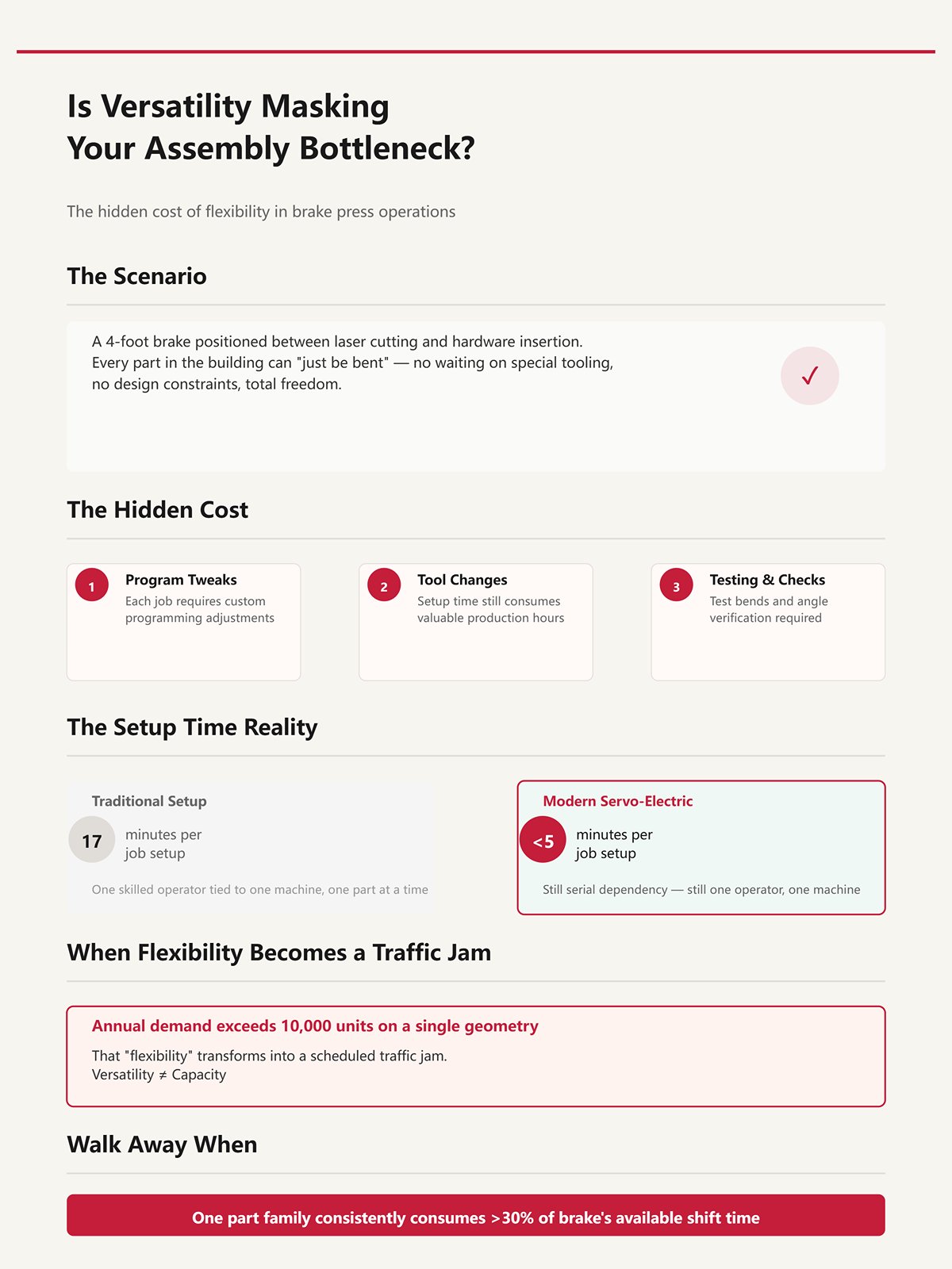
Picture a 4-foot brake parked between laser cutting and hardware insertion. Every part in the building can “just be bent.” No waiting on special tooling. No design constraints. Total freedom.
Now watch the queue build.
Each job needs a program tweak, a tool change, a test bend, an angle check. Even with a modern servo-electric brake that cuts setup from 17 minutes to under 5, you’re still tying one skilled operator to one machine, one part at a time. That’s not flow. That’s serial dependency.
When annual demand creeps past 10,000 units on a single geometry, that “flexibility” becomes a traffic jam you scheduled yourself.
Versatility isn’t capacity.
Walk Away When: one part family consistently consumes more than 30% of a brake’s available shift time.
Let’s run a clean hypothetical.
Five bends. Twenty seconds per bend including repositioning. Call it 100 seconds of pure cycle time per part. Be generous and say 5-minute setups thanks to quick-change tooling.
At 20,000 units a year, you’re staring at roughly 2,000 machine hours just in bending time. That’s one brake tied up full-time for over 50 weeks of single-shift production.
Your tooling was cheap. Your machine wasn’t.
A 15–20% cycle improvement from better programming or OEE tracking might claw back a couple hundred hours a year. Nice. But it doesn’t change the physics: one ram stroke forms one bend. Every time.
And if you push that brake 24/7 to keep up, hydraulic models start showing real fatigue after 500,000 cycles. I’ve seen “economy” machines age ten years in five because someone believed they were universal production engines instead of tactical tools.
Cheap tooling only wins when volume is low enough that setup dominates total cost.
So ask yourself: are you paying per part, or per stroke?
| Section | Content |
|---|---|
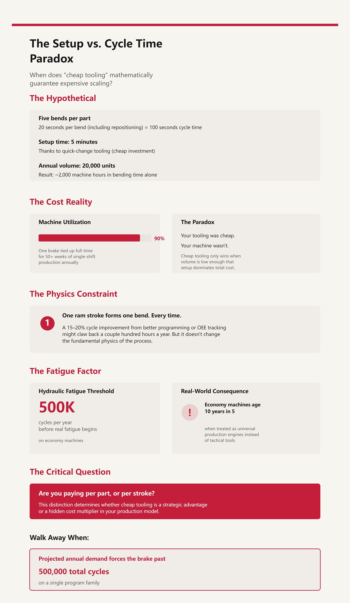
| Title | The setup vs. cycle time paradox: When does “cheap tooling” mathematically guarantee expensive scaling? |
| Hypothetical Scenario | Five bends. Twenty seconds per bend including repositioning. 100 seconds of pure cycle time per part. 5-minute setups thanks to quick-change tooling. |
| Annual Volume Impact | At 20,000 units a year, roughly 2,000 machine hours are required just for bending time. That equals one brake tied up full-time for over 50 weeks of single-shift production. |
| Cost Reality | Your tooling was cheap. Your machine wasn’t. |
| Efficiency Gains | A 15–20% cycle improvement from better programming or OEE tracking might recover a couple hundred hours per year. Helpful, but it doesn’t change the physics: one ram stroke forms one bend. Every time. |
| Equipment Fatigue | Running the brake 24/7 leads hydraulic models to show real fatigue after 500,000 cycles. “Economy” machines can age ten years in five when treated as universal production engines instead of tactical tools. |
| Core Principle | Cheap tooling only wins when volume is low enough that setup dominates total cost. |
| Closing Question | Are you paying per part, or per stroke? |
Walk Away When: projected annual demand forces the brake past 500,000 total cycles on a single program family.
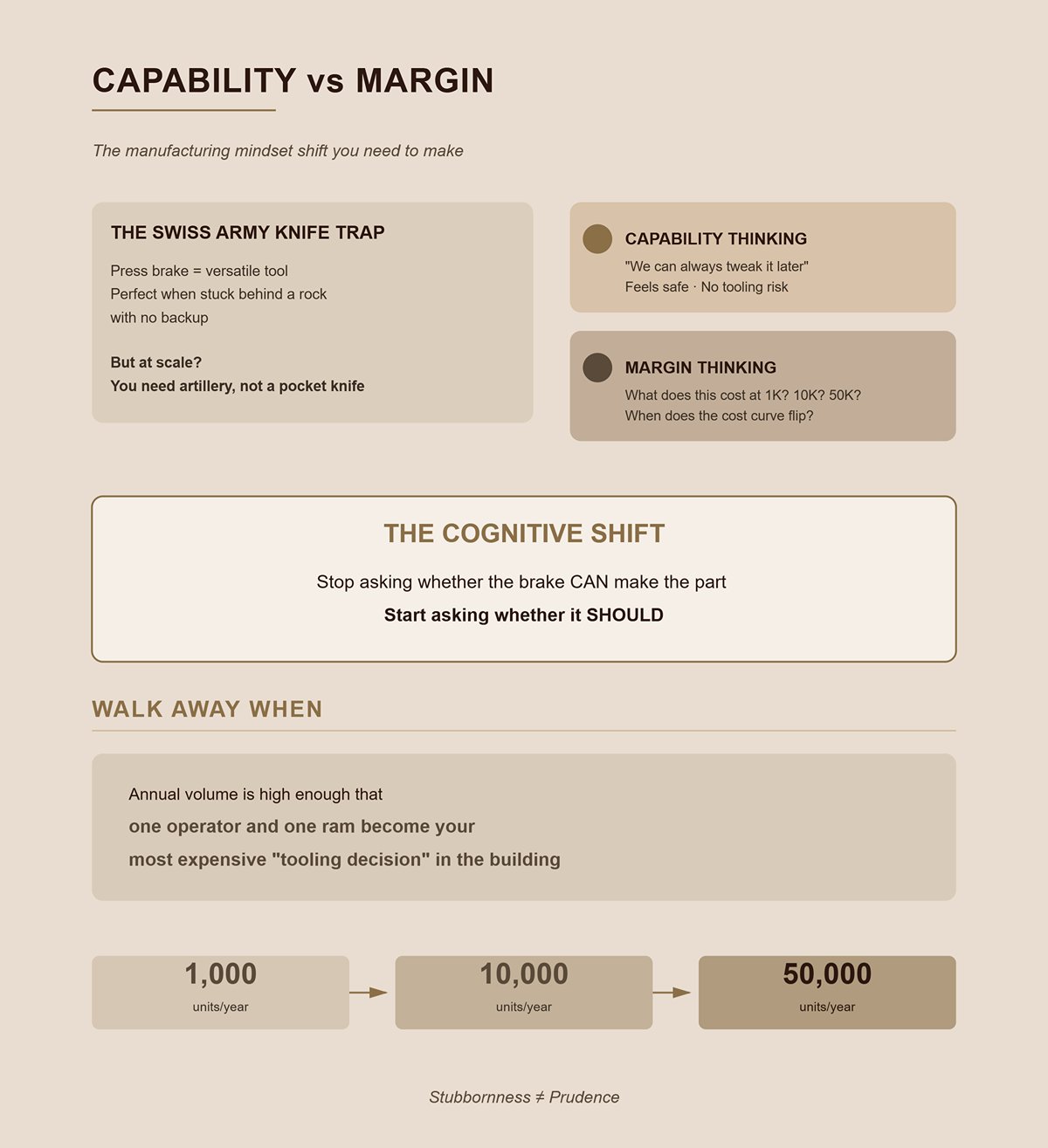
The press brake is a Swiss Army knife. On a battlefield, that’s priceless when you’re stuck behind a rock with no backup.
But if you’re storming a hill every day at scale, you don’t bring a pocket knife. You bring artillery.
I’ve watched OEM teams defend brake-based designs because “we can always tweak it later.” That’s capability thinking. It feels safe. No big upfront commitment. No tooling risk.
Margin thinking is colder. It asks: what does this geometry cost at 1,000 units? At 10,000? At 50,000? And at what point does a dedicated process flip the cost curve so hard that sticking with the brake becomes stubbornness, not prudence?
The cognitive shift you need is simple: stop asking whether the brake can make the part. Start asking whether it should.
Walk Away When: annual volume is high enough that one operator and one ram become your most expensive “tooling decision” in the building.
A medical OEM I worked with ran a seven-bend stainless enclosure at 2,400 units a year. Progressive die quote came back at $180,000. Brake tooling on the rack. Setup under 10 minutes. Two days later we were shipping parts.
They asked the right question: at what volume does the die finally beat the brake?
We ran the math on the floor, not in a conference room. At 2,400 units, even a $6 per-part savings from stamping would only claw back $14,400 a year. That die would sit there for over a decade before it paid off, and that’s assuming geometry never changed. In that range, the brake isn’t a compromise. It’s a margin shield.
But push that same part to 18,000 units and the picture flips. Now you’re burning thousands of ram strokes a week, tying up a skilled operator, and the die amortizes in a few years. Below 100 units, it’s prototype chaos and engineering churn; above 10,000, capacity math starts to dominate. Between those numbers, the brake’s lack of hard tooling isn’t laziness. It’s controlled exposure.
This isn’t convenience. It’s capital discipline.
So where does that 100–10,000 band actually come from?
Stand next to a brake running a 5-bend bracket at 1,000 units a year. You’ll hear more air than steel. Setup time and part handling dominate. The machine is idle more than it’s forming. That’s fine — because your fixed tooling cost is near zero and your cash is still in the bank.
Now picture that same job at 8,000 units. Cycle time starts to matter. The operator builds rhythm. Tool changes drop. Scrap stabilizes. You’re spreading setup over enough parts that the labor drag is tolerable, but not so many that one geometry hijacks the machine.
The structural break happens when annual demand pushes the brake past 500,000 total cycles on a single program family. That’s not a budgeting issue. That’s physics and fatigue. Hydraulic seals wear. Backgauges loosen. Preventive maintenance becomes production downtime. The “flexible” machine becomes your bottleneck.
Inside 100–10,000 units, you’re amortizing setup without triggering capacity collapse. Below 100, you’re in revision mode. Above 10,000, you’re feeding a beast that was never designed to be artillery.
Automation muddies this. Yes, automated press brakes cut downtime and reduce operator dependence. I’ve installed them. They cost real money — often 20–30% more than conventional machines — and they still obey the same constraint: one ram stroke, one bend. You reduce labor per stroke. You don’t multiply strokes per hour enough to change the economic crossover point in a dramatic way.
The sweet spot holds because it’s tied to stroke economics, not nostalgia.
Walk Away When: projected annual demand forces the brake past 500,000 total cycles on a single program family
If volume defines the battlefield, geometry decides the weapon.
I once quoted a telecom chassis with six flange angles: 90°, 45°, 135°, two offsets, and a hem. Laser cut blank. No secondary welding allowed. Annual volume: 3,500 units.
Try building that as a progressive die. You’re stacking stations, adding cams for the odd angles, and babysitting strip layout like it’s a newborn. Tool cost explodes. Lead time stretches. Every angle change means steel work.
On the brake? Swap punches. Re-sequence bends. Adjust backgauge positions. Done.
Complexity multiplies die cost almost geometrically because each station is frozen steel. On a brake, complexity adds seconds and maybe a tool change. That’s linear pain, not exponential pain.
And yes, automation can struggle with high-mix, multi-angle parts. Programming takes time. Skilled operators matter. But when the part demands six distinct bend conditions at mid-volume, the brake behaves like a Swiss Army knife in a tight alley. You can respond without mortgaging the building.
The catch is obvious. Every added bend is another stroke. Every stroke is labor and wear. That’s why this advantage only holds inside the mid-volume band. Complexity plus 40,000 units a year? Now you’re begging for a transfer line or custom forming cell.
Walk Away When: a single geometry exceeds 8 bends and annual demand is trending upward — that’s the point where stroke count, not tooling cost, starts writing your P&L
But even inside that band, there’s a quieter threat to your cash.
A consumer electronics client changed vent patterns and flange lengths three times in eight months. Annual volume hovered around 5,000 units. If we had cut hard tooling up front, each revision would have meant weld build-up, re-machining, or worse — scrapping inserts.
On the brake, we updated the flat pattern, tweaked bend deductions, adjusted the program, and ran first articles the same afternoon.
No waiting on special tooling.
Cash flow matters more than unit cost when designs are still moving. Hard tooling locks geometry. The brake rents it. In the 100–10,000 range, where many OEMs live during product ramp and iterative improvement, that rental model protects you from your own engineering department.
But it doesn’t grant immunity. If revisions settle and volume climbs, the very flexibility that saved you early becomes inertia. You keep “just bending it” because you always have.
That’s where this section hands off to physics. Even inside the profitable window, material thickness, bend radius limits, and springback can quietly sabotage repeatability and cost.
The volume band gives you permission. Geometry and material still decide whether you deserve it.
Last winter I stood in front of a 220‑ton hydraulic brake trying to hit a clean 90° on 0.375″ structural steel brackets. On paper, trivial. In practice, the ram was hovering near 190 tons on every stroke. The angle drifted half a degree as the oil warmed. By hour four, we were shimming dies and chasing numbers like gamblers chasing losses.
That’s the part nobody models in the spreadsheet.
Material thickness, bend radius, and yield strength don’t just influence the bend — they dictate whether the brake is operating in its comfort zone or at the ragged edge of its rating. And once you push a press brake past roughly 80% of its rated tonnage, you’re no longer forming parts. You’re loading seals, deflecting frames, and amplifying every variable in the system.
Inside the 100–10,000 unit sweet spot, the brake makes financial sense. But that only holds if the physics cooperate. The moment thickness and yield strength push tonnage into the red zone, repeatability drops, scrap rises, and downtime starts eating the margin you thought you protected by avoiding hard tooling.
The Swiss Army knife works in tight alleys. It’s not artillery.
So if air bending is the modern standard, why are your “simple” brackets still failing QA?
Air bending is popular because it’s flexible. One V‑die opening can handle a range of angles and thicknesses. You control angle by stroke depth, not by bottoming the punch into a fixed cavity.
But it doesn’t change the physics: one ram stroke forms one bend.
In air bending, the material only contacts the punch tip and die shoulders. The center floats. That means the final angle depends on elastic recovery — springback — which depends on yield strength, thickness, and inside radius. If any of those shift, even slightly, the angle shifts with them.
I’ve seen recycled structural steel lots demand nearly a third more tonnage than the virgin mild steel they replaced. Same nominal grade. Different alloy mix — a little nickel here, a little chromium there — just enough to raise yield strength and fight the bend. The operator doesn’t see chemistry. He sees a part coming off at 91.2° instead of 90°.
You can compensate with depth adjustment. Until you can’t.
Near high tonnage, the machine itself becomes elastic. Frames deflect. Hydraulics lag. Electric brakes above about 150 tons start transferring shock into roller screws that were never meant to live there. Now your compensation curve isn’t just material-dependent — it’s machine-dependent and temperature-dependent.
Tight tolerance brackets fail QA not because the brake is inaccurate. They fail because air bending accuracy assumes stable yield strength and stable machine stiffness. Once either moves, your “simple” two-bend bracket becomes a statistical problem.
And statistical problems cost inspection time.
Walk Away When: achieving tolerance requires live stroke adjustments every shift because material lots swing angle more than your inspection window allows.
But aluminum behaves differently, right?
Take 5052 aluminum and A36 mild steel at the same thickness. Bend both to 90° using the same relative inside radius. The aluminum will spring back more. Not because it’s “softer” — that’s a rookie word — but because its modulus of elasticity is lower relative to its yield strength.
Springback is elastic recovery. It scales with yield strength-to-modulus ratio and inside radius. Higher ratio, more snap-back.
Steel has a higher modulus. It resists elastic stretch more. So for a given plastic deformation, it relaxes less. Aluminum stretches elastically further before and after yielding, so when you release the punch, it opens up more.
Now add radius.
If your inside bend radius approaches material thickness — say 1T — you’re forcing sharper plastic deformation. That reduces springback but spikes tonnage. Open the radius to 2T or 3T to “make it easier,” and springback increases again because you’re bending more gently.
Designers love generous radii on simple brackets. Looks safe. Easier to form.
What they’ve actually done is increase angle variability in air bending, especially on aluminum.
In mid-volume programs, you can dial this in with test coupons and simulation. I’ve seen brakes hold ±0.0004″ position repeatability on complex multi-bend parts when geometry is consistent and tonnage is moderate. That precision is real — but it lives where material behavior is predictable and the brake isn’t straining.
Switch alloys mid-program, or let purchasing chase cheaper coil, and the compensation table you built at 2,000 units becomes garbage at 6,000.
So the question isn’t “Can the brake bend this?” It’s “Will it bend this the same way every lot for the next three years?”
That’s where thickness stops being a detail and becomes a boundary.
Picture a 10‑foot bend in high-strength steel, 0.5″ thick. Even conservatively, you’re pushing toward the upper hundreds of tons depending on die opening. On a 300‑ton machine, you’re flirting with the ceiling every cycle.
Now stack that against annual demand. Mid-volume, say 7,000 units. Two bends per part. Fourteen thousand high-tonnage strokes a year, each near machine limit.
Hydraulic systems damp shock better than electric drives at these loads, but they bring seal wear and oil degradation. I’ve lost two days to seal failure on heavy plate jobs, chasing angle drift caused by pressure inconsistency. That’s not theoretical. That’s payroll running while the ram sits still.
The exact “wrong tool” thickness depends on material yield, bend length, and die width. There isn’t a magic number. There is a line: when required tonnage per foot multiplied by bend length drives you into the top slice of machine capacity, the brake stops being a forming tool and starts being a maintenance liability.
And once that liability lives inside a program expected to run reliably for years, your 100–10,000 unit sweet spot collapses under downtime risk and scrap volatility.
Simple geometries are the most deceptive here. A flat bracket with two long bends in thick, high-yield material looks trivial compared to a six-flange chassis in 14‑gauge. But the chassis runs at moderate tonnage with stable springback. The “simple” bracket punishes the machine every stroke.
That’s the trap.
The brake dominates when complexity is high and force is moderate. It sabotages you when geometry is simple but force is extreme.
Which leaves one uncomfortable question: if force defines the ceiling, what happens when the shape itself fights the stroke-by-stroke nature of the brake?
You’re standing at a 12-foot brake, trying to make a 10-foot architectural fascia with a smooth radius along its entire length. The print calls for a gentle arc, continuous. What you actually do is mark 1-inch increments and start “bump bending” — one shallow hit, slide, another hit, slide again.
But it doesn’t change the physics: one ram stroke forms one bend.
A brake is discrete. A curve is continuous. To fake continuity, you stack tiny straight segments next to each other and pray the facets disappear in paint. If that radius runs longer than 36 inches, you’re not forming geometry anymore — you’re approximating it with labor. Meanwhile a roll former feeds coil through matched dies and produces that curve as a native condition of the process, not an imitation.
That mismatch is where margin bleeds out.
When geometry demands continuity, the brake turns into a Swiss Army knife carving artillery rounds. Yes, it can. No, it shouldn’t. The machine doesn’t know it’s wasting time; it just cycles. Your operator doesn’t get faster; he just gets tired.
So what does that look like in production instead of in theory?
I once watched a shop run 4,000 aluminum light coves — each 8 feet long, each with a shallow sweeping profile. They programmed 22 hits per part to approximate the curve. Twenty-two strokes. Slide, align, stroke. Repeat.
That’s 88,000 ram cycles just to fake a radius.
The brake didn’t struggle on tonnage. It struggled on arithmetic. Each stroke adds handling time. Each reposition adds cumulative angle error. Over 8 feet, a tenth of a degree drift per hit stacks into visible twist. QA didn’t reject them for being out of spec at a single bend. They rejected them for looking wrong.
Now add the physical constraint: most brakes top out around 10 to 12 feet of bed length. Need 16 feet? You’re welding two sections. Every seam becomes a corrosion site, a vibration crack initiator, a warranty claim waiting for a cold winter.
Roll forming doesn’t just win on speed here. It wins on structural continuity. One uninterrupted grain flow along the length. No weld seam. No stacked tolerances from 22 indexed hits.
And yes, roll forming demands commitment — finished coil, dedicated tooling. If your finish has to change mid-run or your design is still floating, the brake gives you flexibility. That flexibility is real.
But if you’re running a stable profile in the mid-thousands and paying a skilled operator to babysit 20-plus strokes per part, you’re burning skilled labor on geometry a continuous process produces automatically.
Walk Away When: your linear profile requires more than 12 discrete hits to approximate a single visual surface.
So long profiles expose the brake’s discreteness. What about depth — when geometry folds back on itself?
Picture a 14-gauge steel electronics enclosure, 20 inches deep, four return flanges, tight corners. On the flat pattern, it’s clean. On the brake, it’s a chess match.
First bend is easy. Second bend clears. By the third, the formed flange starts crashing into the ram housing. You flip it, use gooseneck punches (relieved tooling that clears formed legs), maybe even stage tool heights. Each adjustment adds setup time and new interference risk.
The geometry isn’t fighting tonnage. It’s fighting extraction.
A brake forms by pushing material into a V-die. That means the part must travel into and out of the die space without colliding with tooling or the machine throat. As depth increases, your degrees of freedom collapse. Sometimes the only way out is splitting the enclosure into two shells and welding later.
Which puts you right back into secondary operations, distortion from heat input, and rework to chase squareness.
Now compare that to a dedicated deep-draw or progressive die for higher volume. One controlled motion, designed clearances, predictable material flow. Expensive upfront, yes. But extraction is engineered into the process, not negotiated bend by bend.
Press brakes shine on multi-bend geometries that stay shallow and accessible. Once depth forces creative fixturing and specialty punches, you’re paying for cleverness every cycle.
Walk Away When: enclosure depth exceeds 18 inches and requires staged tooling or part flipping to clear previous bends.
Depth exposes physical interference. Large radii expose something subtler: the brake’s dependence on elastic recovery.
Take 0.125-inch 5052 aluminum. The print calls for a 3-inch inside radius along a 6-foot panel. Generous, right? “Easy bend.”
No. It’s a shallow plastic deformation spread over a wide arc. In air bending, that means more elastic behavior relative to plastic. Springback increases. Angle control gets touchy. And because you’re forming a wide arc with a V-die, you’re not truly generating a radius — you’re generating tangents that imply one.
To get closer to a true 3-inch radius, you either bump-bend in many small increments or move to a radius die that matches the curve. Radius dies at that scale get bulky fast. Tooling cost climbs. Handling gets awkward.
Roll forming creates large radii naturally because the material transitions gradually through sequential stations. Rolling machines do the same in fewer passes for simpler arcs. The material is guided through curvature, not struck into it.
Laser-cut-and-form is the third option designers forget: segment the curve intentionally with relief cuts, then fold along engineered lines. Now the geometry is honest about being discrete. The brake stops pretending to be a roller.
There are exceptions. Thick structural aluminum that must resist oil canning may demand press braking because roll forming can’t handle the gauge without distortion. That’s a durability call, not a speed call. If field performance justifies it, you pay the labor tax knowingly.
But when large radii show up on thin, long panels in stable volumes, the brake is the wrong physics engine for the job.
You can force it. Shops do every day.
You just shouldn’t pretend it’s efficient.
Walk Away When: a required inside radius exceeds 2 times material thickness over a span longer than 36 inches on thin-gauge stock.
Once geometry itself misaligns with the stroke-by-stroke nature of the brake, the machine stops being a flexible solution and starts being an expensive workaround. And if geometry alone can erode margin at moderate volumes, what happens when you add scale to that mismatch?
A Midwest fabricator I know ran a simple bracket on a brake for years. Five bends. Two operators. About 45 seconds of handling and cycling per part. At 5,000 units a year, nobody complained. “ No waiting on special tooling.”
Then the OEM forecast jumped to 60,000.
Nothing about the geometry changed. Same five bends. Same 0.090 steel. Same brake. But now those 45 seconds became 750 operator hours a year tied to one SKU. Add setup, inspections, pallet moves, and you’re past 900 real hours. That’s half a skilled guy’s year, bent into one repetitive motion.
This is where geometry’s inefficiency multiplies. Every extra stroke you tolerated at 3,000 pieces becomes a payroll line item at 60,000. Every flip becomes fatigue. Every collision check becomes risk. The brake didn’t get worse. Scale made it honest.
So what actually shifts when volume crosses into five figures?
Start with a blunt hypothetical.
Assume a brake cell costs you $75 per loaded hour all-in — wages, burden, machine depreciation, electricity, supervision. If a part consumes 45 seconds of real cycle time, that’s about $0.94 per part in machine time alone. At 10,000 units, you’re spending $9,400 in pure brake time. Annoying, but survivable.
At 50,000 units, that same geometry quietly eats $47,000.
Nothing exotic happened. You just multiplied inefficiency by scale.
Now compare that to a progressive die quoted at $30,000. At 10,000 units, the die amortization is $3 per part before you even feed steel. Of course the brake wins there. That’s why the 100–10,000 range is its home turf.
But at 50,000 units, that same $30,000 die adds $0.60 per part. And the press that runs it may cycle at 40 strokes per minute with one operator tending multiple machines. Your per-part labor collapses because the process isn’t discrete anymore — it’s continuous.
But it doesn’t change the physics: one ram stroke forms one bend.
On a brake, five bends will always be five strokes. On a progressive die, five forming events happen inside one press cycle. The geometry doesn’t disappear. It gets embedded in steel.
The moment annual demand crosses 50,000 units, labor stops being background noise and becomes the dominant term in the equation. That’s when “cheap tooling” turns into expensive repetition.
Walk Away When: projected annual demand forces the brake past 500,000 total cycles on a single program family
Let’s solve it instead of guessing.
Take that same 45-second brake cycle at $75 per hour. That’s $0.94 per part in machine time. Ignore material. Ignore overhead. Just labor and machine burden.
Set the die cost at $30,000.
Break-even volume = Die Cost / Brake Cost per Part $30,000 / $0.94 ≈ 31,915 parts.
That’s it. Around thirty-two thousand pieces, the die’s entire capital cost equals what you would have paid just to stand there stroking the brake.
And this assumes a modest five-bend part. Add complexity — say eight bends at 70 seconds — and your per-part brake cost jumps to roughly $1.46. Now break-even drops below 21,000 units.
This is why the “50,000 rule” floats around shops. It’s not magic. It’s a buffer. It accounts for revision risk, maintenance, engineering time, and the reality that forecasts slip.
But the math doesn’t care about folklore. Simpler parts tip earlier. Complex parts tip sooner still. A YouTube case I saw showed a shop dropping from about $12 per brake-formed part in tiny batches to $0.44 with a dedicated die at 10,000 units. Extreme example, yes. But it proves the tipping point isn’t fixed — it’s geometric.
Now layer in a complication: multiple lengths of the same profile. Stamping may require separate dies per length, fracturing your volume and pushing break-even back up. That’s where the brake claws some territory back, because one toolset can flex across SKUs.
But if one geometry, one length, one stable forecast dominates your demand, the operator’s hourly rate becomes the most expensive “tool” in the building.
So ask yourself: are you paying people to create value, or to repeat motion?
Walk Away When: die amortization per part drops below your brake cell’s direct labor cost per part
Stand in front of a 200-ton gap-frame press running a progressive die. You’ll hear 30 to 60 hits per minute. Each hit produces a finished part or advances one through the stations. One operator loads coil and watches strip feed.
Now walk back to the brake cell forming the same bracket.
Clamp. Stroke. Open. Flip. Stroke. Gauge check. Stack.
At 50,000 units, that contrast isn’t academic. It’s payroll.
If a progressive die runs 40 strokes per minute, that’s 2,400 parts per hour in a simple one-out configuration. Even if real output is half that after scrap and checks, you’re still north of 1,000 per hour. The brake at 45 seconds per part produces 80 per hour on a good day.
That’s more than a 12-to-1 throughput gap.
Throughput is margin’s silent partner. Higher throughput spreads fixed overhead — supervision, floor space, maintenance — across more parts. Your per-unit burden shrinks without you negotiating a single material discount.
There are exceptions. Thick plate that pushes tonnage beyond practical stamping limits? The brake may be the only sane option. Variable-length enclosures with shifting designs? Tooling fragmentation can erode stamping’s edge. Those are strategic calls, not emotional ones.
But for stable, repeatable geometry in the tens of thousands, stamping and roll forming don’t just edge out the brake.
They mathematically bury it.
The brake is a Swiss Army knife on a battlefield — indispensable in tight, tactical situations. But when you need artillery, you don’t hand your crew pocket tools and hope efficiency scales.
The real question isn’t whether the brake can make the part.
It’s whether it should be allowed to.
The math already told you when stamping wins.
What it didn’t tell you is how OEMs still light money on fire after that point — because they release geometry that quietly locks the supply chain into the wrong process before anyone runs the numbers.
I’ve watched purchasing teams chase pennies on piece price while engineering hard-coded brake logic into CAD: flange lengths that only work with tall punches, bend orders that require manual flips, continuous shapes broken into discrete hits because “that’s how we’ve always made it.” By the time volume grows, the design itself resists artillery.
Defensive design means you test geometry, tonnage, and forecast together before RFQ. Not after the toolroom quotes you into a corner.
The frame is simple. Brutal, but simple.
Look at the part and ignore how you’ve always made it.
Is it truly a cluster of discrete bends — brackets, tabs, offsets — or is it pretending to be a continuous profile that just happens to be chopped into strokes?
Because a brake is a positional machine. It forms angles at locations. But it doesn’t change the physics: one ram stroke forms one bend.
Now layer in length. Modern CNC brakes with crowning and deflection compensation can hold impressive consistency over long spans. I’ve seen four-meter machines behave better than old three-meter dinosaurs ever did. But push past roughly 3 meters in a single critical bend and you’re fighting beam deflection, material variation, and operator touch all at once. Two degrees of drift across the span isn’t a theory — it’s a Tuesday.
If your geometry demands continuity — long radii, flowing profiles, repeatable sweep — you’re asking a Swiss Army knife to behave like a roll former. That’s not flexibility. That’s denial.
Continuous demand belongs in continuous processes. Discrete geometry belongs on a brake.
Walk Away When: the profile’s functional performance depends on angle uniformity across spans exceeding 3 meters and annual demand is stable enough to justify dedicated tooling.
This is where CAD heroics quietly tax your supply chain.
Minimum flange length isn’t a suggestion. For typical air bending, you need about four times material thickness to even seat properly in the V-die. Tighten the angle to 30 degrees and that requirement jumps by a factor of 1.6× because the material wants to slip and rotate.
So what happens when you stack tight internal returns, shallow hems, and short flanges?
The fabricator either:
None of that shows up in your should-cost model.
Custom punches kill flexibility across SKUs. Now the “universal” brake cell needs part-specific steel — the exact disease you were trying to avoid by not stamping.
If your geometry forces special tooling just to clear itself, you’ve already lost the brake’s core advantage: “ No waiting on special tooling”.
Walk Away When: a single program family requires dedicated punch profiles that cannot be reused across at least 70% of adjacent SKUs.
I’ve seen million-dollar OEMs skip a $0.002 relief feature.
No corner relief at an inside bend means the material binds at the intersection. The operator feels it immediately — extra force, audible pop, inconsistent angle. So they slow down. They re-hit. They check more often.
Cycle time stretches. Not 5%. I’ve measured slowdowns approaching 40% in real cells because the operator can’t trust the hit.
Add relief and the bend flows. The material has somewhere to go. The hit becomes repeatable. Repeatability is speed.
This isn’t about elegance. It’s about friction — literal friction between material and die shoulders. Every time you skip a relief, you’re taxing throughput.
And remember where we started: once volume climbs, repetition is the most expensive thing in the building.
Walk Away When: production feedback shows repeated angle correction or double-hits caused by geometric interference that could have been eliminated in CAD.
Now bring the math back — but this time with geometry discipline.
Bottom bending (coin forming to eliminate springback) can deliver beautiful repeatability for high-volume parts. It also demands roughly 2× the tonnage of air bending and radius-specific dies. That means heavier presses, tighter setups, and tooling that does one job extremely well.
Below meaningful volume, that die-specific investment is a boat anchor.
Above it, that same investment collapses variation, inspection time, and labor touch. Your process window tightens. Your staffing model simplifies. Your scrap rate stabilizes.
Here’s the non-obvious part: switching to stamping or roll forming isn’t just about per-piece cost. It’s about risk concentration.
Brake forming spreads risk across labor skill, setup consistency, and operator sequencing. Hard tooling concentrates risk upfront — in design freeze, die build, and forecast accuracy.
If your geometry is stable, your demand predictable, and your tolerances punish variation, concentrated risk is cheaper than distributed chaos.
That’s the lens.
Not “Can the brake make it?”
Not even “Where’s the break-even?”
But this:
Are you designing a part that deserves artillery, or one that genuinely benefits from a Swiss Army knife?
Get that answer right before release, and your margins survive scale.
Get it wrong, and the shop floor will decide for you — one ram stroke at a time.


