

He had a fresh sheet of 3 mm mild steel on the bed, a shiny new “punch” clamped up top, and the confidence that comes from thinking metal works like paper.
He hit the foot pedal expecting a clean hole.
What he got was a loud thud, a shallow crater, and a tooling edge that would never be square again.
That word on the invoice said punch. So why didn’t it punch?
In a stamping shop, a punch is a hardened tool that shears metal against a die opening. It slices. The clearance between punch and die is measured in hundredths of a millimeter so the material fractures cleanly. That’s cutting.
In a press brake, the “punch” is the upper tool that pushes sheet into a V-die to create a bend. No clearance for shearing. No fracture zone. The tip radius is designed to control inside bend radius, not to act like a blade. On modern CNC-based systems such as a press brake from CN-HAWE, the entire machine structure and control logic are engineered specifically for bending accuracy and repeatability—not piercing—so tool geometry, frame rigidity, and motion control all serve the bend, not the cut.
Same word. Different job.
If you walk up to a press brake expecting it to behave like a punch press, don’t be the guy who finds out the difference with a ruined sheet and a red invoice. The name sets a trap. The physics decides the outcome. So what exactly is your brain assuming when you hear punch?
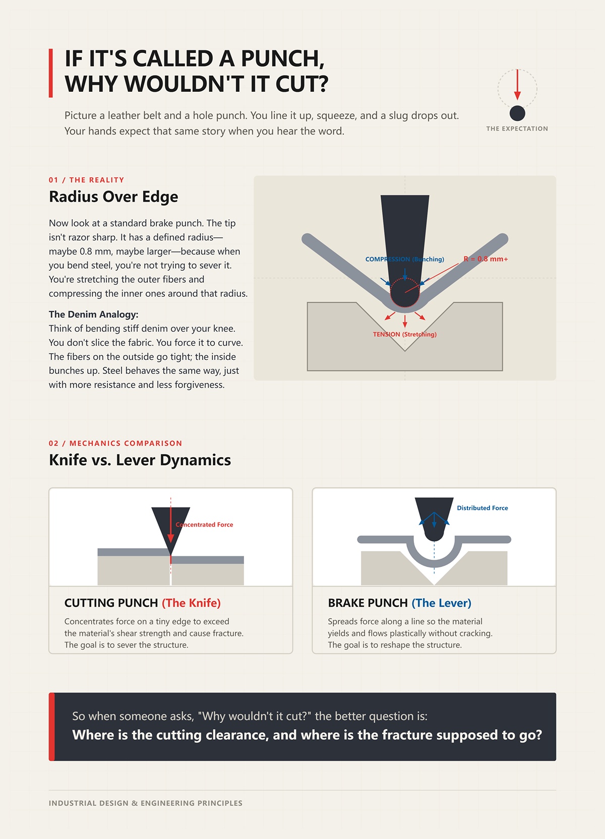
Picture a leather belt and a hole punch. You line it up, squeeze, and a slug drops out. Your hands expect that same story when you hear the word.
Now look at a standard brake punch. The tip isn’t razor sharp. It has a defined radius — maybe 0.8 mm, maybe larger — because when you bend steel, you’re not trying to sever it. You’re stretching the outer fibers and compressing the inner ones around that radius.
Think of bending stiff denim over your knee. You don’t slice the fabric. You force it to curve. The fibers on the outside go tight; the inside bunches up. Steel behaves the same way, just with more resistance and less forgiveness.
A cutting punch concentrates force on a tiny edge to exceed the material’s shear strength and cause fracture. A brake punch spreads force along a line so the material yields and flows plastically without cracking. One is a knife. The other is a lever.
So when someone asks, “Why wouldn’t it cut?” the better question is: where is the cutting clearance, and where is the fracture supposed to go?
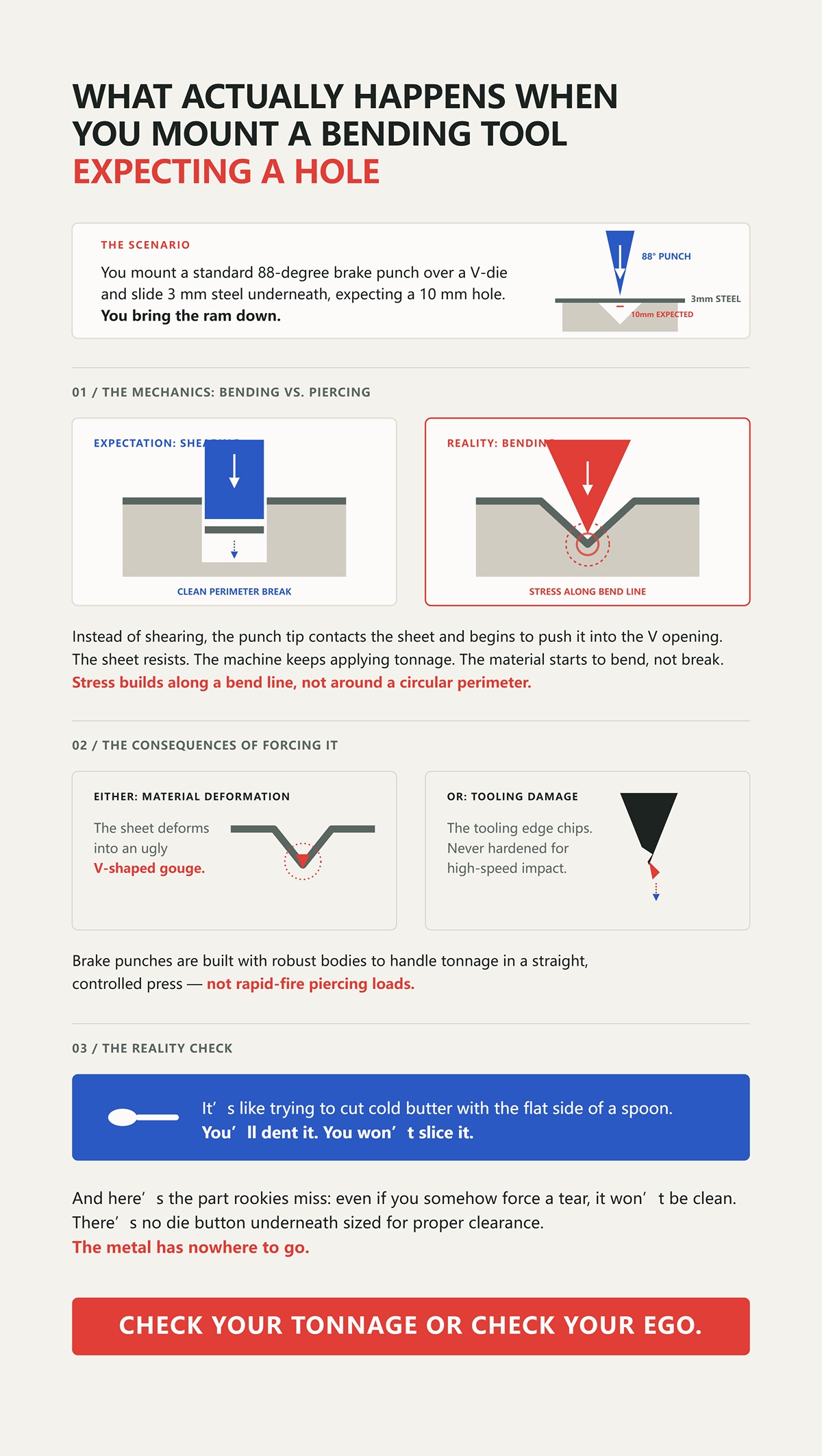
Let’s say you mount a standard 88-degree brake punch over a V-die and slide 3 mm steel underneath, expecting a 10 mm hole.
You bring the ram down.
Instead of shearing, the punch tip contacts the sheet and begins to push it into the V opening. The sheet resists. The machine keeps applying tonnage. The material starts to bend, not break. Stress builds along a bend line, not around a circular perimeter.
If you keep forcing it, two things happen. Either the sheet deforms into an ugly V-shaped gouge, or the tooling edge chips because it was never hardened for high-speed impact and fracture like a turret punch tool would be. Brake punches are built with robust bodies to handle tonnage in a straight, controlled press — not rapid-fire piercing loads.
It’s like trying to cut cold butter with the flat side of a spoon. You’ll dent it. You won’t slice it.
And here’s the part rookies miss: even if you somehow force a tear, it won’t be clean. There’s no die button underneath sized for proper clearance. The metal has nowhere to go. Check your tonnage or check your ego.
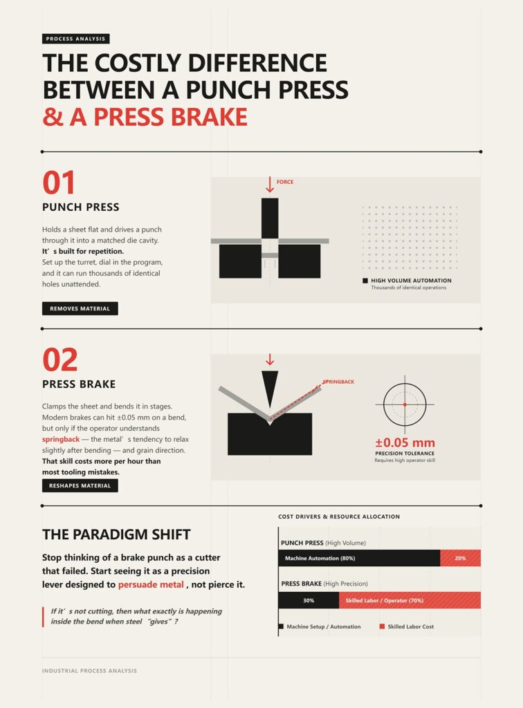
A punch press holds a sheet flat and drives a punch through it into a matched die cavity. It’s built for repetition. Set up the turret, dial in the program, and it can run thousands of identical holes unattended. That’s how long-run parts make money.
A press brake clamps the sheet and bends it in stages. Modern brakes can hit ±0.05 mm on a bend, but only if the operator understands springback — the metal’s tendency to relax slightly after bending — and grain direction. That skill costs more per hour than most tooling mistakes.
One machine removes material. The other reshapes it.
Confuse them, and you don’t just risk broken tools. You misprice jobs, choose the wrong process for volume, and burn labor where automation would have printed cash. Or you chase speed with a brake when what you needed was a turret punching holes all night.
The shift you need is simple but uncomfortable: stop thinking of a brake punch as a cutter that failed. Start seeing it as a precision lever designed to persuade metal, not pierce it.
If it’s not cutting, then what exactly is happening inside the bend when steel “gives”?
You’ve got 3 mm mild steel sitting across a V-die. The punch comes down and touches the sheet at a single line along its radius. The sheet, at that moment, is only touching two other places: the sharp shoulders at the top of the V.
Three contact points. That’s the whole story.
As the ram continues down, the metal doesn’t split. It pivots. The die shoulders act as fulcrums, and the punch becomes a lever applying force between them. The outer surface of the sheet goes into tension — it stretches. The inner surface goes into compression — it bunches. When the stress in that outer layer exceeds the steel’s yield strength, the atoms slide past each other permanently. That’s plastic deformation. No fracture zone. No slug. Just controlled yielding.
If this were cutting, the force would be concentrated on a razor edge and paired with tight clearance so the material shears cleanly. The clearance between punch and die is measured in hundredths of a millimeter so the material fractures cleanly. Here, there is no such clearance because fracture isn’t the goal. The punch is not trying to pass through the sheet; it’s driving it into a shape defined by the die opening.
Like bending stiff denim over your knee. You don’t tear the fabric. You persuade it until the fibers rearrange.
So the real question isn’t “Why didn’t it cut?” It’s “How is the force being distributed, and where is the metal allowed to flow?”
In air bending — which makes up the vast majority of brake work — the punch never forces the sheet to the bottom of the V. It stops somewhere above it. The final angle depends on how deep the punch travels into the opening, not on the die angle alone.
Picture an 88-degree punch over a 90-degree die. You bring the ram down partway. The sheet contacts the punch tip and the two die shoulders, forming an open triangle underneath. The metal is literally bending in the air between those three points. That’s why it’s called air bending.
The accuracy comes from ram depth control. A fraction of a millimeter deeper changes the angle. The die shoulders are the pivots; the punch is the force applicator and depth gauge.
Now compare that to bottoming. In bottom bending, you drive the sheet firmly into a die that has, say, an 88-degree included angle. The sheet is pressed until it contacts the die faces. The die angle now determines the bend angle more than ram position does. You’re conforming the metal to the die geometry.
And if you go even further into coining, you crush the material slightly into the die bottom — forcing it past its natural bend radius by brute tonnage. That can take three to five times the force of air bending because you’re not just yielding the outer fibers; you’re compressing and ironing the entire bend zone.
That tonnage jump tells you something important.
Force alone doesn’t define the process. How and where that force is applied does. Air bending uses leverage and controlled depth. Bottoming uses die conformity. Coining uses localized compression to lock the angle. None of them rely on a sharp edge slicing through steel.
Don’t be the guy who thinks more tonnage turns a forming tool into a cutter. Check your tonnage or check your ego.
Take two punches. One has a 0.8 mm tip radius. The other is ground to a knife-like edge.
The sharp one looks mean. It feels decisive in your hand. But mount it over a standard V-die and try bending 3 mm steel, and you’ll see the problem fast. The sharp tip digs in, creating a tiny inside radius that overstretches the outer fibers. Micro-cracks start. Surface finish suffers. Tool life drops because that thin edge can’t distribute load.
The 0.8 mm radius, on the other hand, spreads the force over a controlled arc. That radius largely determines the inside bend radius of the part during air bending. And that inside radius determines how much the outer surface must stretch.
Here’s the mechanism: the smaller the punch radius relative to material thickness, the higher the strain in the outer fibers. Too tight, and you exceed the material’s elongation limit — it cracks. Too large, and you get a big inside radius that may not meet print.
So the “working edge” is not sharpness. It’s the relationship between punch radius, die opening width, and material thickness and strength.
Even the die opening width matters. A common rule of thumb for mild steel is a V-opening about 6 to 8 times material thickness. That ratio influences the resulting inside radius and required tonnage. Narrower die, tighter radius, higher tonnage. Wider die, larger radius, lower tonnage.
Geometry decides how the metal flows. Sharpness just decides how fast you ruin tooling.
If the punch is a lever, its radius is the part that touches the work. Would you rather press cold butter with a knife edge or with the curve of a spoon when you’re trying to shape it, not slice it?
Bend that 3 mm mild steel to 90 degrees in air bending. Release the ram.
It won’t stay at 90.
As soon as the pressure comes off, some of the elastic strain — the part that didn’t permanently yield — recovers. The bend might open to 92 degrees. That’s springback. Every material has it. Higher-strength steels have more of it because a greater portion of the deformation remains elastic.
What does that mean in practice?
If you want a true 90, you might have to bend to 88 under load. You deliberately overbend so that when the material relaxes, it springs back into spec. The punch must travel deeper than the final angle suggests.
That alone proves the punch isn’t a piercing tool. A cutter stops when it breaks through. A forming punch must anticipate how the material will behave after the load is gone. You’re not just shaping metal under force; you’re predicting how it will move once the force disappears.
That prediction depends on material grade, thickness, grain direction, die width, and punch radius. Change any one of them, and the springback changes.
So when a rookie says, “It looks like 90 under pressure, we’re good,” I make him release the ram and measure again.
Because bending isn’t about forcing steel into submission. It’s about understanding how it yields, how it stores energy, and how it gives some of that energy back.
Now that you see what’s happening inside the bend — leverage, controlled yielding, springback — the next question writes itself:
If geometry controls the flow, how do you choose the right punch shape for the job?
I watched a kid bend 3 mm mild steel with a brand-new straight punch, 0.8 mm tip radius, standard 88-degree profile. First bend went fine. Second bend was 20 mm away, forming a return flange. He brought the ram down and the back of the punch body slammed into the first flange before the angle was even close. The sheet didn’t fail. The machine didn’t fail. The geometry did.
Inside that bend, the outer fibers were stretching past yield while the inner fibers were compressing, just like stiff denim folding over your knee. Nothing was being sliced. The punch was acting as a controlled lever, pushing the neutral axis to shift and the plastic zone to form in a predictable arc. But the body of the tool—the steel above that neat little radius—needed physical space to travel. If the profile can’t clear the part you’re creating, you don’t get a bad cut. You get a collision.
That’s why punch geometry is about clearance and control, not sharpness. You’re choosing a shape that lets the material fold without the tool crashing into your own work.
Walk into any shop and you’ll see straight punches mounted by default. Same height, same shoulder width, easy to line up across the bed. For open bends with no nearby flanges, they’re reliable. The profile is symmetrical, the load path is simple, and alignment is forgiving because the body sits directly over the die centerline.
But look at the numbers that get ignored. Thin straight punches—2 mm web thickness or less—run into deformation risk fast when operators push thick plate through narrow V-dies. In one failure review I sat through, once bending pressure climbed past roughly 80 percent of rated tonnage, deformation probability on those thin punches jumped dramatically when used on steel over 3 mm. And sharp straight profiles were limited to about 100 tons per meter before permanent damage showed up.
Why? Because a straight punch body carries load straight down. No relief. No offset. If you pair it with a narrow die to chase a tight radius, tonnage spikes. The force concentrates near the tip and up into a relatively thin cross-section of tool steel. It’s like trying to fold cold butter with the edge of a ruler instead of the curve of a spoon. It works—until it doesn’t.
And then there’s part geometry. The straight punch has shoulders that flare out immediately above the tip. That means any flange sticking up near the bend line becomes an obstacle. The tool doesn’t know your print. It only knows its own shape.
So the straight punch is versatile for simple forms. The minute your part grows a second leg, that same “default” profile becomes the reason you can’t finish the job.
Take that same 3 mm sheet and design a U-shaped channel with two 25 mm flanges. First bend is easy. For the second bend, you need the punch to reach down past the first flange without hitting it.
Enter the gooseneck.
The gooseneck punch has a relieved throat—an S-shaped offset in the body—so the upper mass of the tool sits back from the bend line. That clearance pocket is what allows the previously formed flange to tuck up inside the punch profile while the tip keeps driving the new bend. Nothing about it is sharper. The magic is in the empty space.
But don’t get romantic about it. That offset changes load paths. Now the force from the ram travels through a geometry that isn’t straight down. If your machine leveling is off more than a couple tenths of a millimeter per meter, or your locating pins are loose, misalignment over 0.1 mm starts showing up as uneven flange angles and twist. In industry defect reviews, alignment errors in that range account for a significant chunk of scrap in formed flanges.
A straight punch hides small alignment sins because its mass is centered. A gooseneck magnifies them because the body is stepped back. You solved a collision problem and introduced a sensitivity problem.
So when you choose a gooseneck, you’re admitting the part geometry demands clearance—and you’d better make sure the machine geometry can support it.
Otherwise you’re not matching the profile to the part. You’re gambling that your setup is good enough.
Here’s one that confuses rookies every year.
You need a crisp 90-degree bend in 2 mm stainless. Instead of grabbing a 90-degree punch, you mount a 30-degree acute punch over a standard V-die and air bend to depth. Under load, the sheet wraps partially around that narrow included angle. After springback, it relaxes to 90.
Sounds backward until you look at the mechanics.
An acute punch concentrates contact closer to the centerline early in the stroke. That tighter included angle lets you overbend without the punch shoulders interfering with the die shoulders. You get more angular travel before mechanical interference, which is critical for high-springback materials like stainless.
But here’s the catch. Smaller tip radii on acute punches raise surface strain. On soft aluminum, too tight a radius can leave marks or even initiate cracks if you ignore minimum inside radius guidelines. And if you pair that acute punch with a very narrow V-die chasing a cosmetic inside radius, tonnage climbs fast. Large radius demands force in a narrow opening. The tradeoff inverts what beginners expect.
So you don’t choose a 30-degree tool because it looks aggressive. You choose it because its geometry allows controlled overbend and clearance before interference—while staying within the material’s elongation limits and the machine’s tonnage envelope.
Different profiles exist because parts have shape, materials have limits, and machines have structure. The punch is a lever with a body that must move through space. If its profile doesn’t match the part’s geometry and the material’s behavior, no amount of sharpness will save you.
And once you accept that shape governs success, the next question stops being “Which punch looks right?” and becomes “How much force will this geometry demand from my machine?”
A few years back, a new hire rolled a cart up to my brake with 4 mm mild steel and a 32 mm V-die already clamped in. He asked the only question that matters: “How much force is this going to take?”
Given that CN-HAWE’s product portfolio is 100% CNC-based and covers high-end scenarios in laser cutting, bending, grooving, shearing, for readers who want detailed materials, Brochures is a useful follow-up resource.
Run the standard air-bend tonnage formula for mild steel and that setup lands right around 100 tons over a 3‑meter length. Same sheet. Same die. Switch from air bending to coining, and the required force jumps dramatically because now you’re crushing the material into the die angle instead of letting it float and form. The machine doesn’t care what you call it. It feels pressure.
That number isn’t about sharpness. It’s about leverage. The punch tip is a lever arm pushing the sheet into the V opening. Change the opening width, change the leverage. Change the thickness, change the resistance. The metal behaves like stiff denim: the wider you support it, the easier it folds; pinch it tight and it fights back. So the real question isn’t “Is my punch sharp enough?” It’s “What die opening am I pairing it with, and what does that do to force?”
That’s where the math keeps you alive.
Set a 3 mm sheet over a 24 mm V-die. That’s the classic 8:1 ratio—die opening eight times material thickness. Air bend it, and you’ll usually get an inside radius close to the material thickness. The sheet isn’t being sliced; it’s being stretched on the outside and compressed on the inside until it yields and takes a set.
Now close that die down to 18 mm because you want a tighter inside radius. Nothing else changed. Same punch. Same steel. Tonnage climbs fast. Why? Because a smaller V opening shortens the lever arm. The punch has to push harder to force the sheet into a narrower space. Force concentrates under the tip and at the die shoulders. Stress goes up in the tool steel and in the sheet.
Open the die to 30 or even 36 mm on thicker plate—10:1 or 12:1 ratios—and the required tonnage drops, and the inside radius grows. That larger radius isn’t a defect. It’s the natural result of allowing the material to flow instead of strangling it.
Beginners treat 8:1 like scripture. It’s a starting point, not a law. Thin material under about 3 mm often behaves differently; too wide a die can make angle control sloppy. Thick plate often needs more than 8:1 to keep tonnage in a sane range. The die opening largely determines the inside radius in air bending, and that radius dictates how much the outer fibers must stretch. Stretch them past their elongation limit and you get cracks. Force them into too tight a space and you spike tonnage.
You don’t pick a punch nose radius in isolation. It has to support the radius the die opening will naturally produce. If the die wants to form a 3 mm inside radius and you bring in a razor-sharp 0.5 mm nose, all you’ve done is concentrate stress at first contact. The sheet will still try to form to the die’s geometry. The math wins.
So if the die opening drives radius and force, what happens when you ignore the force side of that equation?
I’ve seen a straight punch with a thin web—about 2 mm through the body—rated safely for around 100 tons per meter. Looked fine on the rack. Clean. Sharp. The operator paired it with a narrow die on 4 mm steel to chase a cosmetic inside radius. The press brake had the capacity. The tooling didn’t.
What he got was a loud thud, a shallow crater, and a tooling edge that would never be square again.
Here’s the trap: machine tonnage is not tooling tonnage. A 170-ton brake doesn’t magically make every punch in the cabinet a 170-ton punch. When you narrow the V opening, required tonnage rises. When you increase material thickness, required tonnage rises. When you coin instead of air bend, required tonnage explodes because you’re plastically deforming the entire bend zone to match the punch angle.
And the load isn’t distributed evenly. A small V-die concentrates force into a smaller contact area at the punch tip and die shoulders. Local stress can exceed the yield strength of the tool steel even if the total machine tonnage looks “within limits.” That’s how you mushroom tips and introduce microscopic cracks that turn into catastrophic failures later.
Tool catalogs publish maximum tons per meter for a reason. Those numbers assume proper die openings and air bending unless stated otherwise. Ignore that context and you’re gambling with hardened steel under hydraulic pressure.
Don’t be the guy who trusts the machine gauge more than the tooling chart. Check your tonnage or check your ego.
But force alone doesn’t tell you when you’ve mismatched geometry to material. The sheet itself starts talking.
Take 2 mm stainless with modest elongation. Run it over a die that gives you about a 2 mm inside radius. Now swap in an acute punch with a very tight nose—say 0.5 mm—because you want a crisp line. On the first few hits, the bend looks fine. By the tenth, you start seeing bright streaks along the bend line and fine surface tearing on the outside radius.
That’s galling and micro-cracking starting to show.
When the punch nose radius is much smaller than the radius the material can comfortably form, the initial contact creates extremely high surface strain. The outer fibers stretch beyond what that alloy can handle. Stainless, especially, work-hardens quickly. Each hit makes the surface harder and less forgiving. The tool begins to pick up material—adhesive wear—because pressure and friction are high. That’s galling.
At the same time, a sharper nose increases springback. The sheet wraps tightly under load, then relaxes more aggressively when pressure is released. Operators respond by overbending—driving deeper to hit angle—which increases force again. Now you’ve created a loop: sharp radius → higher surface strain → more springback → deeper stroke → more tonnage.
Cracks on the outside of the bend aren’t bad luck. They’re a strain calculation you refused to do. Galling on the punch isn’t cosmetic. It’s evidence of pressure and friction beyond what that pairing should see.
Metal doesn’t care what the invoice called the tool. That word on the invoice said punch. What you’re holding is a precision forming lever that must respect thickness, die opening, elongation, and rated load.
Get those aligned, and the bend becomes predictable. Ignore them, and the machine will teach you with noise and scrap.
A young buyer once asked me how to pick the “right” punch radius for 4 mm mild steel on a 32 mm V-die. I told him: start with the die, confirm the natural inside radius it will form, make sure your punch nose supports that radius without concentrating stress, then check the tooling’s tons-per-meter rating against the tonnage chart for that setup. He nodded. Then he ordered a beautiful European-style punch that wouldn’t even mount in his American ram.
You can calculate radius all day. If the tang doesn’t match your machine, it’s a paperweight.
This is where rookies drift back into the “sharp tool” mindset. They think compatibility means “will it make the bend I want?” No. Compatibility starts higher up the stack: will this punch physically seat in the ram, align under load, and transfer force the way the machine was designed to transfer it? Because a brake press punch is a forming lever. And a lever only works if it’s anchored correctly.
So before you obsess over nose radius, you ask a more basic question: does this tool belong in this machine?
Given that CN-HAWE’s product portfolio is 100% CNC-based and covers high-end scenarios in laser cutting, bending, grooving, shearing, if the next step is to speak with the team directly, Contact us fits naturally here.
Pull an American-style punch and a European-style punch off the rack and lay them side by side. The working ends might look similar. The tops won’t. The American tang is wide and heavy, designed for older mechanical and early hydraulic machines with robust clamping bars. European tangs are narrower, often paired with segmented, quick-change clamping systems that rely on precise vertical positioning.
That little difference at the top dictates everything.
I’ve seen shops buy European precision-ground tooling because the catalog promised better angle consistency. Then they discover their older American ram doesn’t clamp it correctly without an adapter. Now you’ve introduced another interface—another stack-up of tolerances—between ram and punch. Under load, even a few hundredths of a millimeter of vertical play changes bend angle along the length. The clearance between punch and die is measured in hundredths of a millimeter so the material fractures cleanly in punching operations; in bending, similar tiny misalignments translate into inconsistent angles across parts.
You think you’re chasing a better radius. What you’re actually doing is stacking tolerances.
Historically, this isn’t an accident. American mechanical presses were built like tractors—big bearing surfaces, visible wear, gradual warning before failure. European hydraulic systems chased precision and quick change. Different philosophies. Different tang geometries. Different ecosystems. Once your machine is built around one, you’re largely committed to it.
Don’t be the guy who buys a beautiful European punch and then learns his American ram won’t even hold it.
And even if you make it fit, should you?
In the late 1960s and 70s, shops ran “hybrid” machines—hydraulic power with mechanical-style rams and clamping layouts. On paper, they worked. On the floor, we chased alignment problems weekly. The ram moved smoothly, but the clamping wasn’t designed for the segmented precision tooling guys were trying to introduce. Result: uneven loading, localized wear, mystery angle drift.
Here’s what happens mechanically when you mix systems.
A European-style precision punch expects a certain clamping pressure distribution and vertical reference surface. Put it in a machine designed for a broader American tang, and you often rely on set screws or adapters to hold position. Under 80 or 100 tons per meter, that interface can microscopically shift. Not enough to see. Enough to change how the lever transmits force into the sheet.
Metal under bending behaves like stiff denim. Press gradually and it flows. Concentrate pressure at one unstable point and it creases where you didn’t plan. When your punch rocks in the clamp, you’re no longer applying force straight down the centerline. You’re introducing side load. That side load doesn’t just affect the part—it affects the ram guides and the tooling shoulders.
Now your carefully calculated nose radius is working through a crooked lever.
Can you run hybrids successfully? Yes, with proper adapters, rated for the load, and with alignment checked across the full bed length using test bends and feeler gauges. But that’s engineering discipline, not wishful thinking.
The question becomes sharper: even if it fits and aligns, can your machine survive the load that punch geometry demands?
In 1974, Cincinnati built a press brake rated around 1500 tons over 10 meters. Today, there are monsters rated 5000 or 6000 tons. So you might think machine strength has outgrown tooling concerns.
It hasn’t.
Most shops aren’t running 6000-ton giants. They’re running 100- to 400-ton brakes over 3 or 4 meters. And every machine has a rated tonnage per foot or per meter based on frame deflection limits. Exceed that, and you don’t just risk tooling—you risk permanent frame deformation.
Here’s the mechanism.
When you narrow the die opening to chase a tighter inside radius, required tonnage rises sharply. If you then select a punch with a small nose radius to “help” that tight bend, you increase contact pressure at the tip. Higher pressure means more total tonnage required to achieve the same angle because you’re resisting material flow instead of allowing it.
That load travels from punch tip, up through the tang, into the ram, across the side frames, and down into the bed. Frames are designed to deflect elastically within limits. Go past that limit often enough, and you change the machine’s geometry. Now even correctly chosen tooling won’t produce consistent angles because the machine itself has taken a set.
I’ve measured machines that were a few tenths out of parallel end to end after years of overloading narrow dies on thick plate. The operators blamed springback. The real culprit was cumulative over-tonnage.
This is why punch selection is not separate from machine capacity. Your punch nose radius must support the die’s natural radius so tonnage stays in the expected air-bending range. Your tang must seat properly so load transfers straight. And your total tons per meter must stay within both tooling and machine ratings.
Otherwise you’re not just bending steel.
You’re bending the machine that’s supposed to bend it for you.
With tooling compatibility sorted, there’s one more fork in the road: when does this forming lever stop being the right tool entirely, and when do you actually need a true punching machine instead?
At what point do you stop trying to make a press brake behave and wheel in a punch press?
The moment you need daylight through the metal.
Up to now we’ve been talking about levers, load paths, and tonnage limits—how a brake punch reshapes material the way you bend stiff denim over your knee. Controlled pressure. Gradual flow. Geometry guiding physics. That whole system assumes you’re forming, not removing.
The second your drawing shows a hole, a notch, a louver, or a cluster of ventilation slots, you’ve crossed a line. Not a tooling line. A physics line.
A press brake moves material. A punch press separates it.
That distinction sounds simple until someone tries to cheat it.
If you need a 10 mm hole in 3 mm sheet, a brake punch will never be the right answer. It has no die clearance for shearing. It has no stripper to pull the sheet off a cutting punch. It has no way to control slug ejection. The clearance between punch and die in a real punching operation is measured in hundredths of a millimeter so the material fractures cleanly. That tight gap is what allows the metal to yield, crack, and separate instead of stretching like taffy.
A brake setup doesn’t have that relationship. It has a V-die meant to support bending, not to act as a shear ring.
Now scale that up.
Say you need 400 ventilation holes in a panel. A punch press clamps the sheet once and indexes it automatically, stepping through position after position at speeds that make manual repositioning look prehistoric. One setup. Repeated strokes. Clean separation every time. That machine was built for repetition and removal.
Try that on a press brake and you’re hand-positioning for every hit, hoping alignment stays true, and pretending a forming lever is a cutting tool.
Don’t be the guy who turns a brake into a slow, angry imitation of a turret press.
And yes, here’s the wrinkle that confuses people: press brakes can handle thicker plate in bending than many punch presses can in piercing. Double the thickness and punching force climbs fast—faster than most beginners expect. There are jobs where a punch press runs out of muscle while a brake shrugs and forms the same thickness all day.
That doesn’t mean the brake should pierce it.
It just means thickness alone doesn’t decide the machine. The operation does.
Bending thick stainless? Brake. Cutting holes through anything? Punch press.
If the part needs daylight, stop arguing with the drawing.
Let me paint you a picture I’ve seen too many times.
That word on the invoice said punch. What he got was a loud thud, a shallow crater, and a tooling edge that would never be square again.
Here’s why.
A brake punch is hardened for compressive loading along its centerline. It expects distributed contact along a bend line. When you try to drive it straight into sheet to “pop” a hole, you concentrate force at a tiny point with no proper die clearance underneath. Instead of clean fracture, the material stretches, work-hardens, and then gives up unevenly. The load spikes. The tip mushrooms or chips. The ram feels a shock it was never meant to feel.
Metal in bending behaves like cold butter under steady pressure. Metal in piercing behaves like a cracker snapping.
Different failure modes. Different tooling geometry. Different machines.
And there’s more than tooling at risk. Without a matched die opening designed for shearing, the force doesn’t travel neatly through a cutting edge into a supported ring. It spreads into the V-die shoulders and back into the ram guides as impact. That’s not smooth hydraulic tonnage anymore. That’s shock loading.
Shock is what loosens clamps, peens tang shoulders, and starts the kind of wear you don’t notice until angles drift for “no reason.”
You won’t see the damage in one hit. You’ll feel it six months later.
Could you engineer a special setup to nibble or partially shear on a brake? In theory, with custom tooling and careful load control, you can do strange things. Shops have done stranger. But by the time you design around all that, you’ve rebuilt a crude punch press inside a machine that was never meant to be one.
And that’s the real boundary.
A press brake punch is a precision forming lever. It coaxes metal into shape. It does not cut it free. When you ask it to separate material, you’re no longer matching geometry to material physics—you’re ignoring both.
So before you fight the setup, ask one clean question: does this feature require removal of metal, or just relocation of it?
Your answer tells you which machine belongs on the floor.
And once you’ve chosen the right machine, how do you make that choice systematic instead of instinctive?
You want a repeatable way to decide between a press brake and a punch press, not a gut feeling and a prayer.
Good. Instinct is what rookies call guessing.
Here’s the framework I teach new hires after they’ve dented something expensive: decide in layers, and let physics veto you at each step. First question: does the drawing require material removal or just relocation? If it needs daylight through the sheet, you’re done—punch press. If it’s all bends, hems, offsets, flanges—now you earn the right to open the brake’s tooling cabinet.
But that’s only the fork in the road. The real discipline starts after you’ve chosen forming. Because a brake will happily let you set up a combination that fits in the clamps and still overloads the bed, mushrooms the punch, or deflects the ram like a diving board.
So the checklist isn’t “Which tool looks right?” It’s “Does this geometry match my material and my machine?”
And that starts with the numbers stamped on the side of the machine that most beginners never read.
Every press brake has a tonnage chart. It tells you, for a given material thickness and die opening, how many tons per foot—or per meter—you need to air bend that material.
That’s not a suggestion. That’s the cost of bending stiff denim instead of T‑shirt cotton.
Say your chart tells you 4 mm mild steel over 3 meters will run close to 100 tons with a certain V‑die. Fine. Your brake says 120 tons max. You think you’re safe.
Maybe.
Now look at centerline load limits. Many 10‑foot 100‑ton machines cap out around 1.3 to 1.5 tons per inch in the center because the bed and ram flex more there. Concentrate too much force in the middle and you don’t just bend steel—you bend the machine. That damage doesn’t show up today. It shows up when your angles drift six months from now and nobody knows why.
And we’re not done.
Tooling has limits too. The land area—the shoulders of the die supporting the load—can only handle so many tons per square foot before it deforms. I’ve seen setups where the machine had headroom, but the die shoulders were past their rating. The tool gave up before the part did.
Don’t be the guy who checks the machine badge and ignores the tooling catalog.
Now layer in material coefficients. Stainless isn’t mild steel with a prettier finish. It needs more force. I’ve watched shops calculate 117 tons for a stainless bend, bump it to 175 after applying a multiplier, and still have to widen the die to bring tonnage back into a safe range. Wider die, less force—but larger inside radius. Geometry shifts. Suddenly the punch radius you picked doesn’t match the new reality.
This is where the checklist earns its keep:
If any layer fails, you redesign—shorter bend segments, different die width, or, if the drawing won’t budge, a different machine.
Sometimes the honest answer is: this brake cannot do this bend at this length.
That’s not defeat. That’s respect for load paths.
Check your tonnage or check your ego.
But even with all the charts lined up, one mental habit still trips people.
The non-obvious shift is this: stop thinking about what the tip of the punch looks like and start thinking about how force flows through the system.
A brake punch is a lever. The ram pushes down. The material rests across a V‑die. Force spreads along a line, not a point. The metal yields gradually, like pressing cold butter with the edge of a ruler. Controlled deformation.
The moment you ask, “Can I just drive this through?” you’ve switched mental models without noticing.
If the feature requires separation, you need die clearance measured in hundredths of a millimeter so the material fractures cleanly. That’s a punch press world—tight clearance, stripper plates, slug control. If the feature requires angle, radius, offset—now you’re managing inside radius, springback, and die width.
Different questions. Different physics.
So here’s the decision method you carry forward:
You’re not choosing between machines based on thickness anymore. You’re choosing based on whether the metal must fracture or flow—and whether your machine can guide that flow without exceeding its structural limits.
That’s the lens.
Stop asking what the punch looks like. Start asking what the metal has to do—and whether your machine can apply that force cleanly, along the right path, for the full length of the bend.
Once you see the job as force management instead of tool selection, you don’t just pick the right machine.
You stop blaming the wrong one.


