

I’ve watched a 36-inch 4-way die sit “perfect” in a holder, shoulder to shoulder, no daylight showing at the ends. Operator ran 120 tons across 10-gauge. The center lifted just enough to slide a feeler gauge under it after the first hit. By the third job, a hairline crack crawled out of the corner radius.
It matched the holder length.
It still failed.
You’re looking at length like it’s support. If the die fills the space, you assume the load has somewhere to go. That’s how apprentices think right before tooling screams.
A 4-way holder isn’t a spacer block. It’s a foundation. If the bed or holder only touches the die at a few high spots, the force doesn’t spread evenly—it jumps between contact points. Steel under load behaves predictably: unsupported spans deflect. And when they deflect under bending force, the stress concentrates at the transition from supported to unsupported material.
That’s where cracks start.
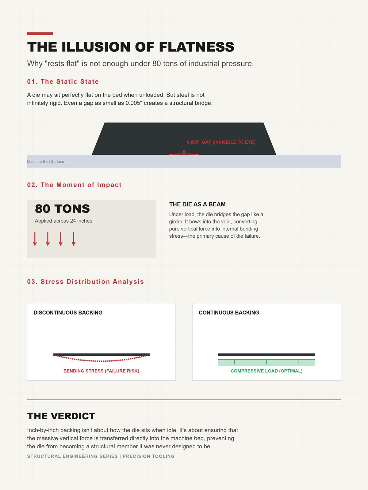
Imagine a die that “rests flat.” You set it in, it doesn’t rock, clamps snug. Looks fine. Now apply 80 tons across a 24-inch section. If there’s even 0.005 inches of gap in the center, the die bridges that gap like a beam. Under load, it bows into it.
You can’t see that movement with your eye. But the steel feels it.
The die body becomes a structural member carrying bending stress it was never designed to carry. 4-way dies are built to disperse vertical load through their mass, not to span voids underneath like a bridge girder. Continuous inch-by-inch backing turns vertical force into compressive load straight into the bed. Break that continuity, and you convert compression into bending inside the die block itself.
So the question isn’t whether it “sits flat” unloaded.
It’s what happens the moment tonnage hits.
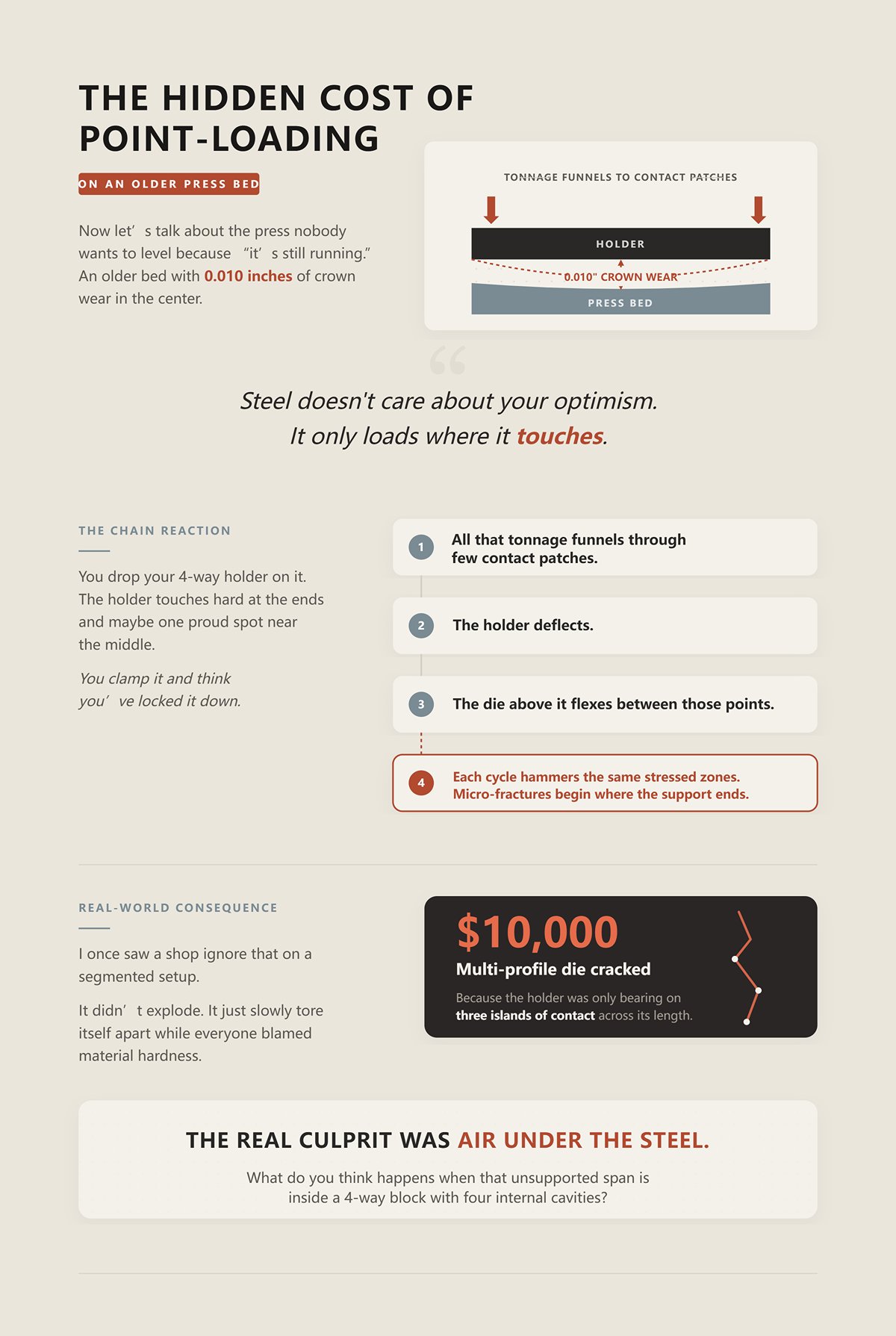
Now let’s talk about the press nobody wants to level because “it’s still running.” An older bed with 0.010 inches of crown wear in the center. You drop your 4-way holder on it. The holder touches hard at the ends and maybe one proud spot near the middle.
You clamp it and think you’ve locked it down.
Listen to me, steel doesn’t care about your optimism. It only loads where it touches.
All that tonnage funnels through those few contact patches. The holder deflects. The die above it flexes between those points. Each cycle hammers the same stressed zones. Micro-fractures begin where the support ends.
I once saw a shop ignore that on a segmented setup. They cracked a $10,000 multi-profile die because the holder was only bearing on three islands of contact across its length. It didn’t explode. It just slowly tore itself apart while everyone blamed material hardness.
The real culprit was air under the steel.
What do you think happens when that unsupported span is inside a 4-way block with four internal cavities?
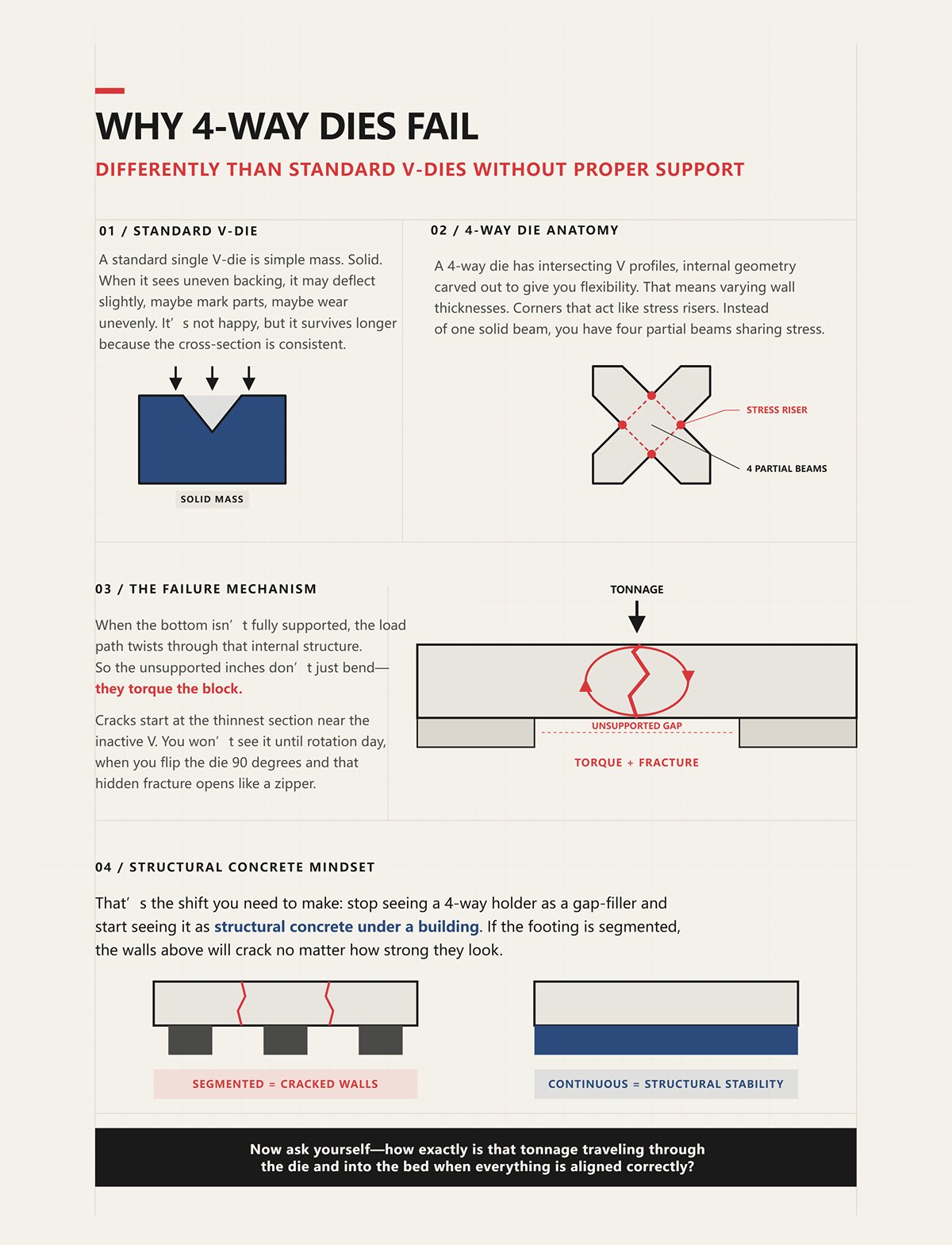
A standard single V-die is simple mass. Solid. When it sees uneven backing, it may deflect slightly, maybe mark parts, maybe wear unevenly. It’s not happy, but it survives longer because the cross-section is consistent.
A 4-way die is different. It has intersecting V profiles, internal geometry carved out to give you flexibility. That means varying wall thicknesses. Corners that act like stress risers. When the bottom isn’t fully supported, the load path twists through that internal structure.
Instead of one solid beam, you have four partial beams sharing stress.
So the unsupported inches don’t just bend—they torque the block. Cracks start at the thinnest section near the inactive V. You won’t see it until rotation day, when you flip the die 90 degrees and that hidden fracture opens like a zipper.
That’s the shift you need to make: stop seeing a 4-way holder as a gap-filler and start seeing it as structural concrete under a building. If the footing is segmented, the walls above will crack no matter how strong they look.
Now ask yourself—how exactly is that tonnage traveling through the die and into the bed when everything is aligned correctly?
A 240‑ton press brake bending 3/4‑inch plate over 36 inches pulls about 126 tons of total force. Sounds safe on paper. But that same machine may carry a bed limit of 40 tons per foot. Spread 126 tons over three feet and you’re at 42 tons per foot—already past what the frame is built to take.
Nothing broke because the total number was too high. It broke because the load was concentrated.
That’s how tonnage actually travels—inch by inch, straight down through whatever steel is touching and nowhere else. When the holder and die are fully backed, the force becomes pure compression into the bed. When they’re not, the force turns into bending inside the tooling and concentrated stress in the frame. The machine doesn’t care what the brochure says about total capacity. It only feels pressure per foot at the contact line.
So when you say, “The brake is 240 tons,” what you should be asking is: how many tons are sitting on each foot of bed right now?
Look at the nameplate on a typical 150‑ton, 10‑foot brake. Many of them are limited to about 25 tons per foot. That’s the structural ceiling of the bed and ram, not a suggestion. You can run a short die and stay under 150 total tons while still exceeding that per‑foot limit in the working zone.
And your holder is sitting right in the middle of that zone.
A 4‑way holder rated for 60 tons across its full 36 inches is not automatically safe at 60 tons over 18 inches. Cut the working length in half and you double the load per inch. The holder’s cross section now carries the same force through fewer contact points, increasing bearing pressure into the bed and bending stress inside the holder body.
This is where shops fool themselves. They match the die length to the holder length. They match the holder rating to the machine’s total tonnage. Everything “matches.”
But the steel feels it.
Load ratings must be read as tons per inch of supported length. If your operation produces 40 tons per foot, then every inch of holder and bed under that die must be capable of carrying 3.33 tons continuously, not just at the ends, not just at clamp points—continuously.
Because force doesn’t teleport to stronger areas. It stays where it’s applied.
Now imagine a narrow-shouldered 4‑way die sitting on a holder that isn’t perfectly flat underneath. The actual contact patch might be only 1/2 inch wide along each shoulder. That’s your real load path.
Take a hypothetical 30 tons over 12 inches. That’s 2.5 tons per inch overall. But if only half the shoulder width is bearing due to slight unevenness, you’ve effectively doubled the contact stress at that line. The pressure spikes locally, even though your math says you’re “within limits.”
Steel under compression is patient. Steel under uneven compression becomes a beam.
If there’s a 0.005‑inch void under the center, the die bridges it. Under load, that span deflects downward. Even a few thousandths of deflection in a hardened multi‑profile block changes internal stress from vertical compression to bending tension at the lower fibers. Tension is what cracks tool steel, not compression.
And in a 4‑way die, those internal cavities mean the neutral axis—the line where stress flips from compression to tension—isn’t centered like a solid block. The thinner walls near the inactive V see higher tensile stress first. That’s where hairlines begin.
Not because you exceeded total tonnage.
Because you concentrated it under a narrow, partially supported shoulder.
Start with 0.002 inches of bed wear in the center. Add 0.001 inches of scale or debris under the holder. Add 0.002 inches of machining tolerance between holder and die base. None of those numbers scare anyone alone.
Stack them and you’re at 0.005 inches of potential gap.
That gap converts vertical force into a bending moment every cycle. The holder flexes slightly. The die flexes slightly more. When you unclamp, it springs back—almost. Over hundreds of hits, that almost becomes permanent set. Now the die no longer “rests flat” even unloaded. The next job starts with built‑in misalignment.
Listen to me, fatigue doesn’t announce itself. It accumulates at the exact transition between supported and unsupported steel.
When alignment and backing are correct, tonnage travels straight down: punch to die shoulder, shoulder to holder face, holder face to bed, bed into the frame. A clean, vertical compressive column. No torque. No span. No tension zones hiding inside a cavity.
When alignment is sloppy, that column kinks. And once it kinks, the internal geometry of a 4‑way die magnifies the distortion instead of absorbing it.
That’s why holder architecture—how it supports, centers, and distributes load—decides whether those forces stay vertical or start tearing sideways through your tooling.
On a 12‑foot brake rated 25 tons per foot, we once set up a 36‑inch 4‑way die in three different holders and ran the same job: 3/8 plate, heavy air bend, right at 22 tons per foot in the working zone. Same machine. Same die. Same tonnage. Three completely different stress patterns showed up in bluing and feeler gauges.
Nothing about the die changed.
Only what was under it.
That’s the part most shops treat like a spacer. If failure is driven by load concentration and micro‑deflection, then the holder is not an accessory — it is the footing. Change the footing, and you change whether that force column stays vertical or starts to bow sideways through the cavities of a multi‑profile block. So what in the architecture keeps that column straight?
Take a true monolithic 4‑way holder: one continuous, machined body, ground flat end to end, doweled and keyed so it self-centers in the bed. No seams. No interrupted shoulders. When you torque it down, it becomes an extension of the brake’s lower beam.
Now load it at 22 tons per foot across the full 36 inches.
Because the body is continuous, the compressive stress distributes along the entire base. Any micro high spot is absorbed by elastic compression across the whole length, not concentrated at a joint. The holder behaves like a single deep beam in compression, not three short beams butted together. That matters because beam stiffness scales with section continuity; break the section and you slash the moment of inertia at the break.
In high-tonnage work — say anything consistently above 20 tons per foot — that continuity stops being “nice to have.” It becomes mandatory. The die shoulders push down. The holder face pushes back up uniformly. The bed carries it. No hinge points. No local rotation.
Imagine a die that “rests flat” across 36 inches of ground steel, with less than 0.0015 inch variation end to end. Under load, the deflection curve is smooth and predictable. The neutral axis inside the 4‑way block stays centered. You keep the stress in compression where tool steel is strong.
But monolithic holders cost more, weigh more, and demand precise bed condition. So the question becomes: can segmented designs give you the same vertical load path with more flexibility?
Set three 12‑inch segments side by side. Clamp them tight. From five feet away, they look like one piece.
They aren’t.
Each joint is a potential hinge. Even if the top faces are ground, the mating ends rarely share load perfectly. Under 22 tons per foot, if one segment is just 0.002 inch lower due to bed wear or debris, the adjacent segment takes a disproportionate share until elastic deformation equalizes it. That equalization is deflection. Deflection inside the holder becomes bending inside the die.
The mechanism is simple. A segmented holder interrupts the compressive path with vertical seams. Those seams reduce lateral stiffness. When load hits near a joint, the segment can rotate microscopically about its base because its neighbor is not structurally bonded — only clamped. Clamping force resists separation, not rotation under bending moment.
Does that mean segmented holders are junk? No.
At moderate loads — say under 15 tons per foot — with tight bed tolerances and proper doweling, they can perform acceptably. They shine in setups where you’re shifting multi‑V dies a few inches left or right for flexibility. European multi‑V systems get versatility by sliding engagement along one solid block. Segmented holders try to mimic that flexibility underneath. The difference is the die remains monolithic; the support does not.
And the steel feels it.
The more you chase versatility, the more carefully you must control joint flatness, alignment keys, and end-to-end preload. Without precise self-centering features — tapered keys, ground tongues, controlled end gaps — you are stacking micro‑deflections right where your die cavities are thinnest.
So if segmentation introduces hinges, what happens when someone decides to “solve” a length mismatch with a saw?
I watched a shop cut a 48‑inch holder down to 30 because “it matched the holder length” they needed for a short run. Clean cut. Deburred. Looked professional.
They had just sliced through the internal rib that tied the base to the upper shoulder.
Most quality holders are not simple rectangles. They’re engineered with internal mass distribution — thicker webs under the load line, relief pockets away from it — so the compressive path stays directly beneath the die shoulders. When you cut one, you often remove the end constraint that keeps the section from spreading under load. You change the boundary conditions from fixed to partially free.
Under 20+ tons per foot, that matters. The shortened holder now has reduced torsional rigidity and altered stress flow. The remaining section must carry the same per‑inch load with less structural continuity. You’ve created a beam with a compromised flange.
I lost a $10,000 multi‑profile die early in my career because of that exact move. Hairline crack started at the inactive V nearest the cut end. We were within total tonnage. We were within nominal per‑foot rating. But the backing was no longer continuous. Micro‑rotation at the unsupported end turned vertical compression into bending tension inside the die cavity wall.
Listen to me, when you cut a standard holder, you are not trimming excess steel. You are cutting through the structure that keeps load vertical.
If you truly need custom length, the holder must be designed that length from the start — with webs, ribs, and mass placed for that span — not amputated after the fact.
Because once you understand that load travels inch by inch, the next question isn’t about total capacity anymore.
It’s about what happens during rotation, repositioning, and mid‑swap — when that support is briefly disturbed and the die has to settle back into the same vertical column without shifting sideways.
You rotate a 4‑way die ninety degrees. It drops back into the holder. Looks seated. You run the next bend at 22 tons per foot.
But it came back 0.002 inch off-center.
That is what happens to the load column during rotation. It doesn’t disappear. It fractures. The vertical compressive path you built inch by inch gets interrupted, then rebuilt by gravity and friction instead of geometry. If the holder does not force the die back to center with a mechanical reference — not eyeballing, not tapping with a mallet — the steel chooses its own position. And the steel does not choose perfectly.
Under load, that 0.002 inch becomes a lateral moment arm. Compression at the shoulder turns into bending inside the cavity wall. You won’t see it on the first hit. You will see it after the fiftieth profile change.
So which centering system actually survives real use?
Picture two setups.
First: a flat-bottom holder. No centering keys. The operator sets the 4‑way block in place, nudges it against a backgauge finger, clamps it, and calls it good. It passes a basic safety audit. Guards are in place. Two-hand control works. Nothing illegal.
Second: a holder with precision-ground V-channels and tapered centering keys. The die drops in and is forced to a repeatable centerline within 0.001 inch by geometry alone. No tapping. No guesswork.
On paper, both pass inspection. In motion, only one keeps the load column intact.
Manual alignment depends on friction between the die base and holder face. Friction resists sliding; it does not correct misalignment. During a 90-degree rotation, the die lifts, pivots, and re-seats. If the holder face has even 0.0015 inch variation end to end — and most beds do — the die will settle toward the low side. Gravity is stronger than your eyeball.
Now run 18 tons per foot. The ram descends. The shoulders engage. The die tries to equalize under load, but it can’t translate freely because it’s clamped. So it rotates microscopically. That rotation pushes tensile stress into the inactive V opposite the working cavity.
Self-centering V-channels change the mechanism. They convert vertical seating force into lateral alignment force. When the die drops, the tapered faces drive it to the geometric centerline before clamping. The centering is structural, not procedural.
Which one survives a real audit — the kind where someone asks why your multi-profile die cracked at the unused station?
The one where alignment is built into steel, not left to habit.
But centering alone doesn’t stop movement during the flip itself.
| Aspect | Self-centering V-channels | Manual Alignment (Flat-bottom holder) |
|---|---|---|
| Basic Setup | Precision-ground V-channels with tapered centering keys | Flat-bottom holder with no centering keys |
| Die Positioning Method | Geometry forces die to repeatable centerline within 0.001 inch | Operator manually nudges die against backgauge finger |
| Alignment Mechanism | Structural centering built into steel | Procedural alignment based on operator habit |
| During Rotation | Die guided back to center by tapered faces | Die lifts, pivots, and re-seats based on friction and gravity |
| Dependence on Friction | Minimal; alignment driven by geometry | High; friction resists sliding but does not correct misalignment |
| Bed Variation Impact (0.0015 inch) | Geometric centering compensates for variation | Die settles toward low side due to gravity |
| Behavior Under Load (18 tons/ft) | Maintains load column integrity | Microscopic rotation pushes tensile stress into inactive V |
| Risk of Cracking at Unused Station | Significantly reduced | Increased due to induced tensile stress |
| Audit Outcome (Basic Safety Check) | Pass | Pass |
| Audit Outcome (Root-Cause Scrutiny) | Alignment justified structurally | Alignment dependent on operator consistency |
| Overall Reliability | Repeatable, structural alignment | Variable, friction-dependent alignment |
Take a 36‑inch multi-profile die weighing a few hundred pounds. You unclamp it. You hook it. You begin the 90-degree rotation.
Mid-rotation, the center of gravity passes outside the base footprint. For a moment, the die is a pendulum.
If the holder provides only a flat shelf, nothing prevents lateral shift except your rigging control. If it provides side retainers, capture lips, or a dovetail engagement, the die remains constrained even when partially lifted.
Here’s the mechanical difference: during a flip, the contact condition changes from full-face compression to edge contact and then to point contact. In that transition, any clearance becomes travel. A lateral clearance of 0.003 inch at the base can translate into angular misalignment at the shoulder once reclamped.
Under 20 tons per foot, that angular error produces asymmetric shoulder loading. One shoulder sees higher compressive stress; the opposite wall experiences bending tension. Tool steel tolerates compression beautifully. It hates tension.
Listen to me, gravity does not care about your production schedule. If the holder does not positively locate the die throughout the rotation arc — not just when fully seated — you are gambling alignment every time you switch profiles.
And most shops switch profiles dozens of times a shift.
Which brings us to the damage you don’t see coming.
Imagine a shop running four different V-openings on one 4‑way block. Ten rotations in the morning. Ten more after lunch. Each time, the die re-seats within 0.001–0.003 inch of its previous position — but not exactly.
Under 15 tons per foot, maybe you get away with it. The elastic deformation is small. The steel shrugs.
Push past 20 tons per foot, and those tiny misalignments stop being elastic housekeeping. They become cyclic stress reversals in the inactive cavities. One run loads the east wall slightly harder. Next rotation loads the north wall. Then west. Then south.
You have created low-amplitude, multi-directional bending cycles in hardened tool steel.
Not enough to snap it in a day.
Enough to nucleate micro-cracks at the thinnest cross-sections — usually between adjacent V-cavities where material is already relieved for clearance. Each rotation rebuilds the load column imperfectly. Each imperfect rebuild adds another microscopic scar.
Shops blame “bad heat treat.” Or “cheap tooling.”
But the pattern tells the truth: cracks appear at profile transitions, not at peak-tonnage single-V jobs. The common factor is rotation without deterministic re-centering and full backing.
The holder is the footing. The centering system is the surveyor. If the surveyor lets the building shift a hair each time it’s repositioned, the foundation will not fail in compression. It will fail in fatigue.
And if the holder can do everything right, what happens when the press itself won’t repeat that same centerline after every stroke?
If your holder re-centers perfectly but the ram wanders a hair left or right every stroke, the load does not disappear.
It relocates.
Force always transfers at the interface. Not in the catalog drawing. Not in the sales pitch. At the steel-to-steel contact where your die meets whatever stack you’ve built between it and the machine. If that stack includes adapters, transition blocks, mismatched tangs, or a crowning system fighting the bed, that is where the wandering ram first shows up as deflection.
Imagine a die that “rests flat.” It looks seated. It matched the holder length. But the steel feels it.
When the ram comes down slightly off center, the die wants to shift laterally to re-establish a straight compressive column. If your interface is one continuous, inch-by-inch bearing surface, the load redistributes as compression. If it’s segmented—die to adapter, adapter to holder, holder to bed—each interface becomes a hinge with its own micro-clearance.
That hinge is where bending begins.
You’re not marrying shapes. You’re marrying load paths. And the weakest wedding in the stack sets the terms of the marriage.
So where does that force actually enter the system?
A tang is just a rectangular tongue that drops into a slot in the holder. Tangless systems clamp the full base with hydraulic or mechanical jaws. Both will “hold” a die. Only one defines the load path clearly.
With a traditional tang, vertical force enters through the die shoulders into the base, then concentrates at the tang faces and slot walls. The contact area shrinks. The pressure rises. If the ram is a hair off center, the tang bears unevenly against one wall of the slot before the rest of the base even knows what happened.
Now picture a tangless base with full-face clamping and upward draw. The clamping force pulls the die into a repeatable seat before tonnage arrives. The vertical load then spreads across the entire base-to-holder interface. The interface is broad. The pressure per square inch drops. The system behaves more like a foundation than a dowel pin.
Short load path. Broad bearing. Fewer hinges.
But don’t romanticize it. I’ve seen shops bolt tangless multi-profile dies onto old American holders with crude side clamps and call it “compatible.” It wasn’t. The die was vertical-loading by design; the holder was side-entry by geometry. The force path kinked at the adapter plate in between.
Listen to me, compatibility is not “it fits.” Compatibility is “the force travels in a straight, fully supported line from ram to bed.”
If it changes direction inside your adapter stack, you just built a pivot point.
So what happens when you mix entire tooling families?
American-style tooling slides in from the side. European-style drops in vertically and locks upward with pins or wedges. Both can bend parts all day. The difference shows up when you stack them.
Say you run a European multi-profile die on an American press using transition blocks. The block converts vertical clamping geometry into side-slot geometry. On paper, it’s rated for the tonnage. In practice, you’ve inserted another interface: die to block, block to holder.
Each interface has flatness tolerance. Each has parallelism tolerance. Stack three of them across a 10-foot bed and you have tolerance accumulation that your eye will never see—but your die will feel every stroke.
Under 20 tons per foot, a few tenths of a thousandth just flex and come back. Push to 30 tons per foot, and those same tenths become alternating stress as the ram drifts and the crowning system compensates. The adapter becomes the first element to tilt microscopically. The die follows.
That tilt is not dramatic. It’s a few microns. Enough to move compression off-center and introduce tension at the thinnest web between V-profiles.
I once watched a shop crack a $10,000 multi-profile die because they “made it work” with cut-down transition blocks that left gaps under two inches of the base. It matched the holder length. The prints said it was fine. Six weeks later, hairline fractures showed up exactly where the backing stopped.
They blamed heat treat.
But the crack traced the edge of the unsupported span like a map.
Now, to be fair, modern universal adapter systems can hold ±0.1 mm repeatability across machines. When engineered as a single, integrated clamp—designed to eliminate stacked tolerances—they behave like a continuous foundation. That’s real compatibility.
The question is simple: are you adding pieces, or are you installing a system?
Because every added piece is a potential hinge.
And even if you get the interfaces right, there’s still the machine itself bending under load.
Every press brake bed deflects under load. Physics doesn’t clock out because the nameplate says precision. Crowning systems—manual wedges or CNC-controlled hydraulic compensation—pre-bow the bed so the ram and bed meet parallel under tonnage.
Here’s the quiet problem.
If your holder is rigid in one segment and shimmed or stacked in another, the crowning system is no longer bending a single continuous structure. It’s bending a layered assembly with different stiffness at different points. The machine compensates for bed deflection. Your adapter stack compensates differently. The die sits between two arguments.
But the steel feels it.
If the holder foundation is continuous and matched in stiffness to the bed, crowning creates uniform contact pressure along the die length. If the holder is segmented, crowning can actually amplify pressure at the seams, because those joints compress differently than solid steel.
You end up with localized overloading even when your tonnage calculation says you’re safe.
This is where most shops get blindsided. They assume the machine’s compensation will save them from minor interface sins. It won’t. Compensation only works when the structure being compensated behaves as one piece.
So before you ask whether your 4-way die will “fit” your press, ask a harder question: does the entire stack—from ram to bed—act like a single, continuous foundation under load?
Because if it doesn’t, no amount of careful rotation or perfect centering will keep fatigue from finding the weakest seam.
And once you see the stack as a structural system instead of a pile of compatible parts, the decision stops being about convenience and starts being about engineering.
You want a practical way to audit your ram‑to‑bed stack and know whether it behaves like one continuous foundation under load.
Good. Stop eyeballing. Stop trusting catalog claims. You’re going to test it the same way a structural engineer would test a footing: load first, contact second, alignment third.
In that order.
Because if you get the first wrong, the rest is theater.
Before you compare American, European, 4‑way, single V—none of that matters—calculate your worst‑case tons per foot.
Not average. Not what you “usually run.” Worst case.
Take your thickest material, smallest V-opening, highest tensile strength you bend in production. Run the numbers. If your job peaks at 28 tons per foot, then every inch of that holder and die stack must survive 28 tons per foot repeatedly without turning compression into bending.
Now here’s the non‑obvious part.
A lot of frustrated shops discover, on paper, that their press can make 35 tons per foot—but their 4‑way die body is rated for 25 tons per foot in its narrowest V. Or their holder is only rated for 20 tons per foot when mounted with transition blocks.
That disqualifies the stack before you ever check contact.
And yes, that alone eliminates a chunk of shops from safely running multi‑profile dies at the loads they think are “normal.”
You don’t pick a holder and hope it carries the load. You prove the load is within every component’s structural ceiling.
If your numbers are flirting with the rating, you are not “close.” You are cyclically fatiguing steel.
So once you know the real tons per foot, what are you actually asking the holder to do with it?
This is where most people lie to themselves.
They set the die in place. It sits flat. It looks good. It matched the holder length.
Imagine a die that “rests flat” on three slightly proud pads, with a 0.003-inch hollow between them. Unloaded, you’ll never see it. Under 25 tons per foot, those three pads become concentrated columns. The hollow becomes a bending span.
But the steel feels it.
Here’s how you audit it without guessing:
If you can slide even a thin gauge under any section, you do not have continuous support.
Then comes the real test: bump up to moderate tonnage—well below max, but enough to simulate working load. Release. Remove the die. Look for witness marks. Bright contact only at ends or near clamps? That’s segmented loading.
Listen to me, even two unsupported inches in the middle of a multi‑profile die under 30 tons per foot is not “probably fine.” It is a fatigue origin.
Continuous means inch‑by‑inch backing. No daylight. No bridging. No stacked shims behaving differently under crowning.
If contact is correct, the load spreads. If it’s segmented, the die becomes the beam.
So now assume you have true contact. One solid foundation. Are you done?
Not if you’re still chasing centerline with a dead blow hammer.
Structural continuity without centering repeatability is like pouring a perfect footing and then building the walls two inches off the chalk line.
Multi‑profile dies amplify this.
Every time you rotate a 4‑way die, you are asking it to return to the same centerline relative to the ram. If your holder relies on manual nudging, side clamps, or eyeballed alignment, you’ve inserted variability into the load path.
Under low load, you’ll see angle drift. Under high load—say 30 tons per foot—off‑center force introduces torsion in the die body.
That torsion pushes compression to one web and tension to the opposite side between V openings. That’s where cracks start.
Repeatability means:
You should be able to remove and reinstall the die and hold center within a few thousandths without recalibrating your backgauge reference.
If every rotation forces you to re‑tap, re‑measure, re‑tweak, the system is not structurally honest. It’s forgiving you at low tonnage and punishing you at high tonnage.
So now you’ve done three things: verified capacity, confirmed continuous support, and eliminated centering drift.
Here’s the question most owners avoid.
Fast‑change systems save minutes. Adapter stacks save capital. Cut holders save material.
All of that looks smart on a spreadsheet.
But if your stack cannot guarantee continuous backing at your maximum tons per foot, and cannot return to center without human persuasion, then you did not buy a foundation.
You bought a spacer.
Foundations are boring. Heavy. Precise. Overbuilt for what you “usually” do. They exist so that when the machine reaches peak load, nothing inside the stack has to negotiate.
This is the lens I want you to carry forward:
Stop asking, “Will this holder work with my die?”
Start asking, “Does my entire ram‑to‑bed assembly behave like one uninterrupted compressive column at my highest real tonnage?”
That question is non‑obvious because everything looks fine at half load.
Cracks don’t start at half load.
And once you see your stack as a structural system instead of a collection of compatible parts, you won’t shop for convenience.
You’ll shop for continuity.


