

The salesman swiped his finger across a 19-inch touchscreen like he was unveiling a new pickup truck. Big icons. Glossy gradients. “Full CNC,” he said.
Two weeks later, I watched a 10-gauge stainless panel slide into the scrap bin because the backgauge and ram never truly agreed on where they were supposed to meet.
That’s the gap I want you to stare at.
Walk into enough shops and you’ll hear it: “It’s CNC. We’re covered.” As if the label itself guarantees precision.
But I’ve seen median press brake utilization numbers hovering around 12.9%, while top-quartile shops push past 34%. Same machines. Same tonnage class. The difference isn’t the color of the interface. It’s whether the control logic actually prevents the first-bend failure — or politely waits for it to happen on the shop floor.
A touchscreen doesn’t stop you from scrapping 10-gauge stainless. Control logic does.
So what’s hiding behind those “CNC-compatible” stickers?
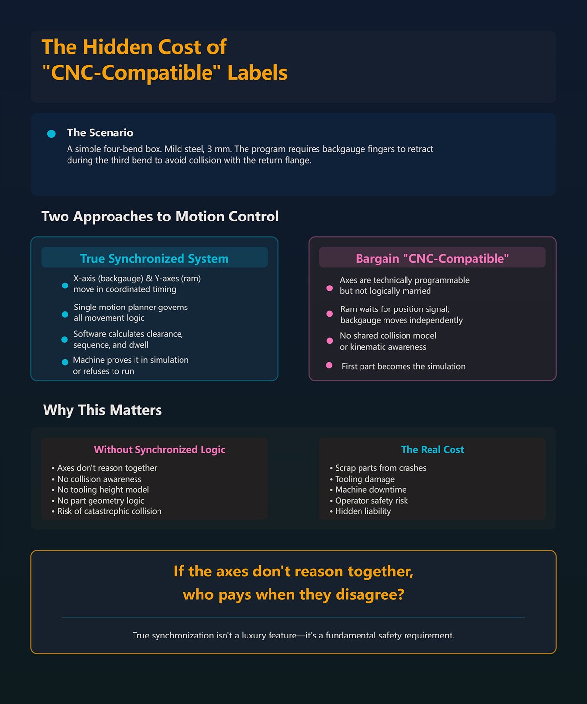
Picture a simple four-bend box. Nothing exotic. Mild steel, 3 mm. The program calls for the backgauge fingers to retract during the third bend to avoid collision with the return flange.
On a true synchronized system, the X-axis (backgauge) and Y-axes (ram cylinders) move in coordinated timing, governed by a single motion planner. The software calculates clearance, sequence, and dwell before the ram commits. The machine either proves it in simulation — or refuses to run.
On a bargain “CNC-compatible” controller, the axes are technically programmable, but not logically married. The ram waits for a position signal. The backgauge moves on its own instruction set. No shared collision model. No kinematic awareness of tooling height or part geometry.
The result? The first part becomes the simulation.
If the axes don’t reason together, who pays when they disagree?
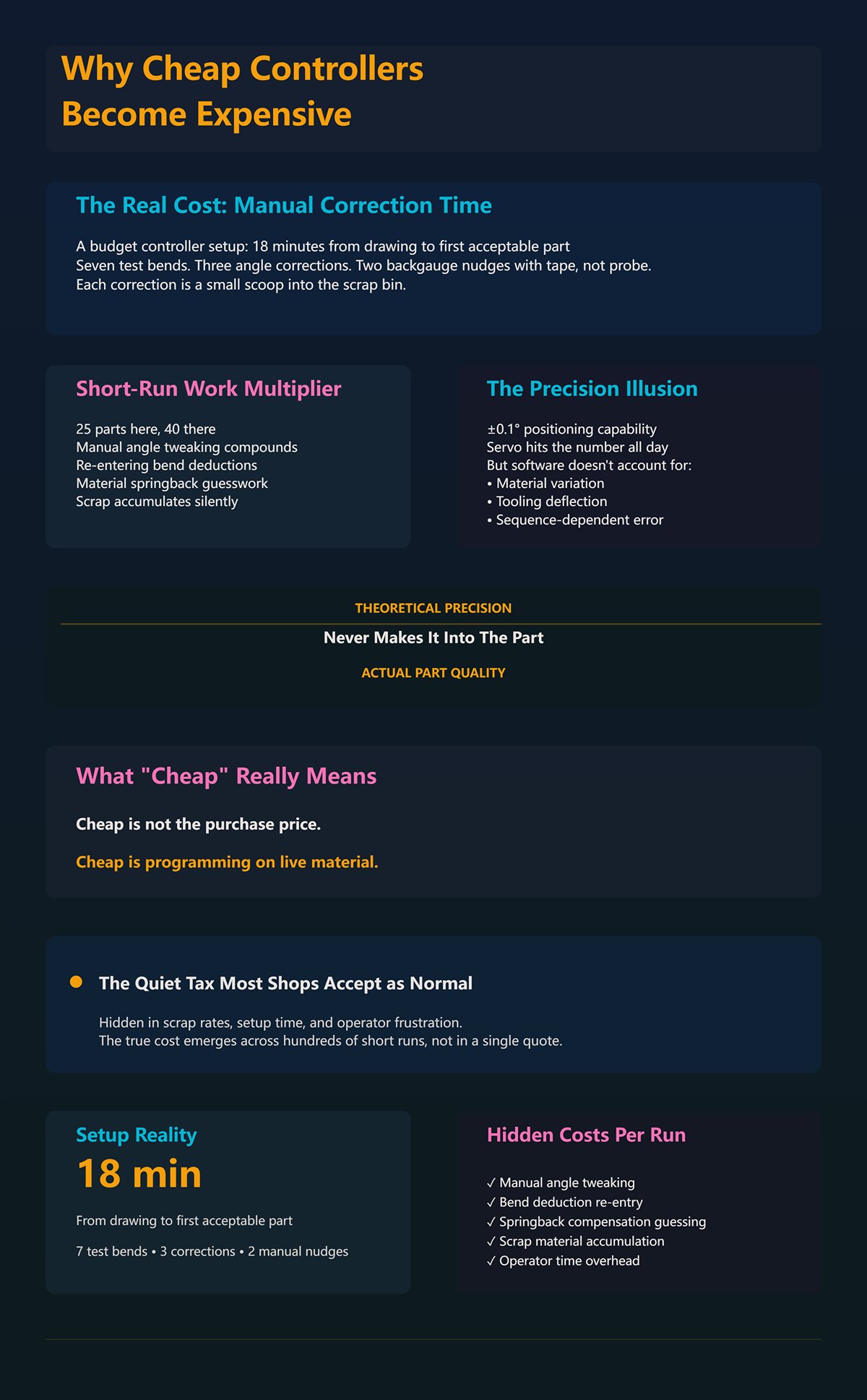
I once timed a setup on a budget controller: 18 minutes from drawing to first acceptable part. Seven test bends. Three angle corrections. Two backgauge nudges measured with a tape, not a probe.
Now run that across short-run work — 25 parts here, 40 there. Those “minor” corrections stack up. Manual angle tweaking. Re-entering bend deductions because the controller can’t compensate for material springback unless the operator guesses it right. Each correction is a small scoop into the scrap bin.
Manufacturers love quoting ±0.1° positioning capability. Fine. The servo might hit that number all day. But if the software doesn’t account for material variation, tooling deflection, or sequence-dependent error, that theoretical precision never makes it into the part.
Cheap isn’t the purchase price. Cheap is programming on live material.
Which leads to the quiet tax most shops accept as normal.
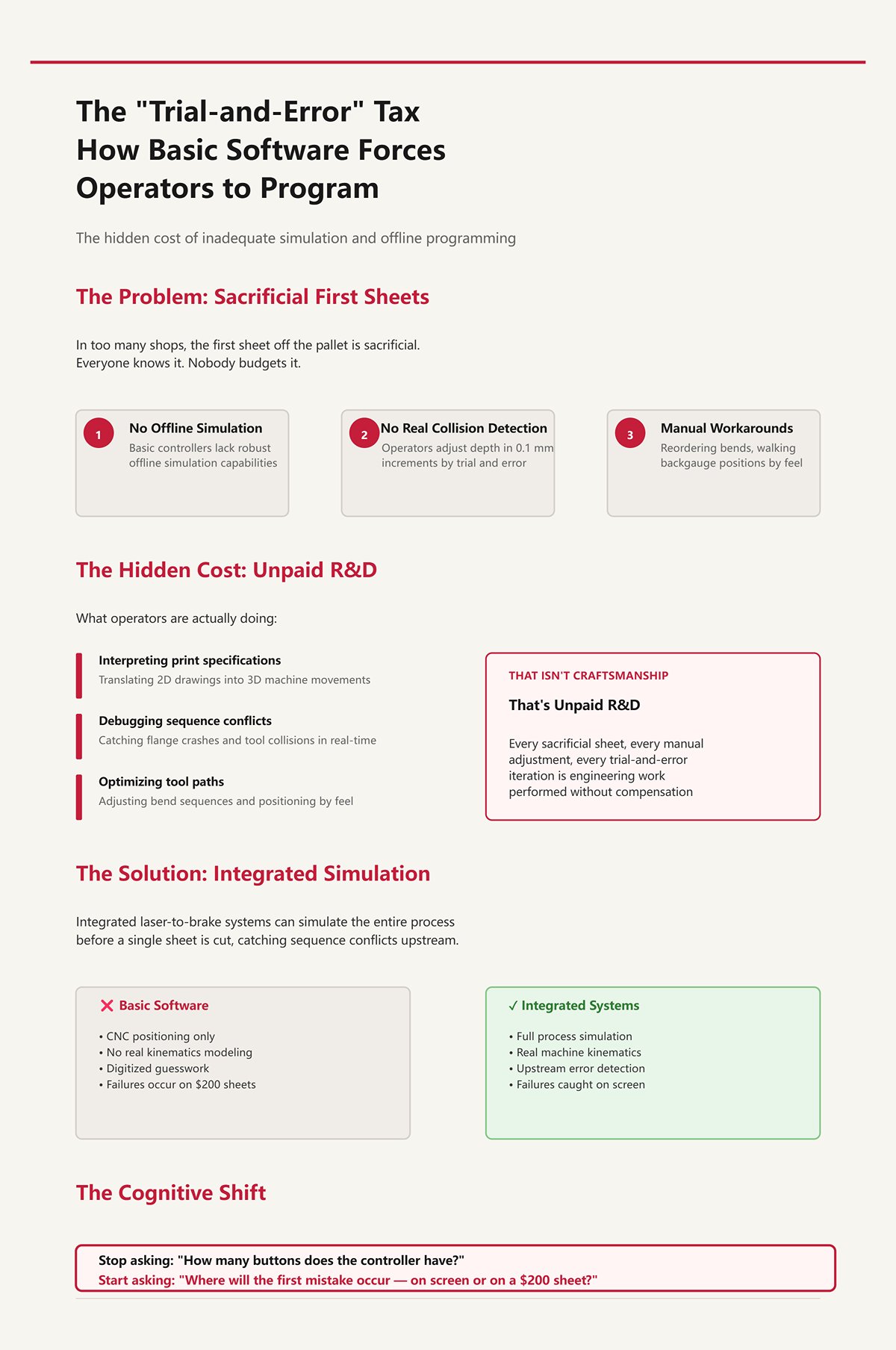
In too many shops, the first sheet off the pallet is sacrificial. Everyone knows it. Nobody budgets it.
Basic controllers lack robust offline simulation or real collision detection. So the operator becomes the interpreter between print and machine, adjusting depth in 0.1 mm increments, walking backgauge positions by feel, reordering bends after a flange crashes into the punch holder.
That isn’t craftsmanship. That’s unpaid R&D.
Integrated laser-to-brake systems can simulate the entire process before a single sheet is cut, catching sequence conflicts upstream. Especially in high-mix, custom work, that simulation is where failure belongs. But when software stops at “CNC positioning” and never models the real kinematics of the machine, you’ve moved nothing. You’ve just digitized the guesswork.
Here’s the cognitive shift I want you to make: stop asking how many buttons the controller has, and start asking where the first mistake will occur — on a glowing screen, or on a $200 sheet of stainless.
Because once you see that, the next question isn’t about screens at all.
It’s about how the software governs every axis in motion.
A few months back I stood behind a six-axis brake bending 4 mm mild steel. On paper, it was a beast: Y1, Y2, X, R, Z1, Z2. Independent fingers. Programmable crowning. The brochure read like a fighter jet spec sheet.
The first part still twisted 0.8° across its width.
We put a gauge on it. Y1 was leading Y2 by a hair during approach — not enough to trigger an alarm, just enough to bias the bend. The backgauge hit its X position, but R hadn’t fully settled before the ram committed. Each axis, by itself, was “within tolerance.” Together, they were out of truth.
That’s the disconnect. Mechanical limits are dictated less by steel and hydraulics than by the logic that choreographs them. If your controller treats axes as separate errands instead of a single coordinated motion plan, you’re not running a precision brake. You’re running an expensive guessing machine that moves very accurately in the wrong sequence.
And that’s how first-bend failure sneaks past glossy gradients and into the scrap bin.
Everyone obsesses over Y1/Y2 synchronization — and they should. The Y-axis is the ram. Without stable, repeatable ram control, nothing else matters. One axis is the minimum viable brake.
But watch a real part being formed. The X-axis sets flange depth. The R-axis sets finger height relative to the die. Z1/Z2 space the fingers to support the blank. Now add a return flange that needs clearance on the third bend.
On a properly integrated controller, those axes don’t just “arrive” at positions. The motion planner calculates a timed path: X retracts 40 mm while Y rises past a safe clearance window; R shifts 12 mm to maintain support as material rotates; Z fingers reposition between bends only after the ram crosses a defined threshold. All of it governed by a shared kinematic model of tooling height, die width, and part geometry.
Collision prevention isn’t a buzzer that screams after contact. It’s code that encodes physical limits — throat depth, punch length, finger geometry — and refuses to execute a sequence that violates them.
Now picture a generic controller where axes wait for simple position flags. X reaches coordinate. Y moves. No awareness that the flange is about to spear the punch holder because the software doesn’t model that punch holder in the first place. The first sheet becomes the clearance probe.
Here’s the over-spec question nobody likes: if your software can’t prove axis choreography in simulation, what good is adding independent Z fingers? More axes just multiply failure points unless the logic binds them into one brain.
Which brings us to the part software either guesses — or knows.
I once bent a 1200 mm length of 10-gauge stainless with basic crowning set by feel. First hit came out 1.5° open in the center. We added shim. Second hit overcompensated. Third was close enough to ship.
Three test pieces gone.
Crowning compensation exists because the ram and bed deflect under load. That deflection isn’t uniform; it depends on tonnage distribution across the length. Advanced software doesn’t just let you dial in a number. It calculates expected deflection from bend length, material tensile strength, die opening, and target angle, then commands a calculated crowning curve before the ram ever touches metal.
Same story with springback. Mild steel at 250 MPa behaves differently than stainless at 600 MPa. A real material library stores tensile strength, yield ratio, and empirical bend deduction factors. When you call up 3 mm 304 stainless, the controller adjusts penetration depth to hit 90° knowing that material will relax more than A36.
Basic software? It asks the operator to “adjust angle correction.” That’s a polite way of saying: bend it and see.
The difference shows up in where the first error lives. With a calibrated material library and dynamic crowning, the correction happens in math. Without it, the correction happens in sheet stock.
But here’s the catch most salesmen skip: that digital twin is only as honest as your calibration. If your tonnage chart is wrong or your crowning cylinders drift, the simulation lies with confidence. So how do you decide what really governs repeatability?
I’ve seen backgauges advertised at ±0.02 mm repeatability. Beautiful number. Laser-etched. ” As if the label itself guarantees precision”
Then the shop runs tight offset bends spaced less than six times material thickness apart — say 3 mm material with 12 mm offsets. Hydraulic pressure spikes unevenly across the bed. The ram slows to maintain return pressure. Y-axis timing shifts slightly under load.
The backgauge can hit its mark all day. If the program sequence doesn’t account for pressure dynamics and bend order, the angle still drifts.
Repeatability is a system outcome, not a component spec.
Programming logic determines bend sequence to minimize cumulative error. It decides whether to form interior flanges first to stabilize the blank, whether to split a long bend into staged hits to control deflection, whether to reposition Z fingers to support weight distribution before a critical bend. Those decisions affect angular consistency more than whether your gauge ball screw was ground or rolled.
So when someone brags about seven controlled axes, I ask one question: does the controller synchronize them under load, with real material data, and prove the sequence before the ram descends?
Because if it can’t, the machine’s physical limits aren’t set by steel and hydraulics.
They’re set by the first mistake you discover after the punch touches metal.
And that mistake should have died in simulation.
You want concrete proof that a controller delivers synchronized, simulation-proven repeatability?
Ask it to fail before you do.
Not on the machine. In the office. In a digital model that knows your punch length, your die shoulders, your throat depth, your backgauge fingers, and the 3 mm stainless you swear behaves “about like last time.” If the software can’t predict a collision, a clearance issue, or an impossible bend sequence before the ram drops, then all that integrated axis logic we just talked about still gets validated the old-fashioned way — by sacrificing a sheet to the scrap bin.
That’s the first-bend failure. Every job has one. The only question is where it lives.
2D and 3D simulation aren’t about pretty screens. They’re about moving that failure upstream, where mistakes cost electricity and coffee instead of 10-gauge stainless and a dinged punch holder. The ROI isn’t the button count. It’s whether your first wrong move happens in pixels or in steel.
So when does 2D stop being enough?
A flat screen can’t show you depth.
For simple brackets — two bends, one plane change — 2D programming at the console works fine. You key in flange lengths, pick a die, follow the bend order the controller suggests, and if your material library is honest, you’re close on the first hit. The geometry is predictable. Clearance is obvious. The operator’s brain fills in the missing third dimension.
But stack three return flanges around a box, add an offset less than six times material thickness, and suddenly clearance isn’t intuitive anymore. In 2D, the controller shows a profile view of each bend, one at a time. What it doesn’t show clearly is how the already-formed flange swings through space during the next bend, how it passes the punch holder, how close it comes to the machine throat. The operator becomes the collision engine.
That’s fine — until it isn’t.
I’ve watched good people “air bend and watch” as their primary verification method. They slow the ram, hover a finger over the stop, and let the first sheet act as a probe. Sometimes they catch the interference in time. Sometimes they polish a groove into a $600 punch. The scrap bin doesn’t care whether the mistake came from bad math or missing visualization.
2D becomes a bottleneck the moment spatial reasoning exceeds what one person can safely simulate in their head.
And high-mix shops hit that wall daily.
Here’s the simple math nobody argues with: if the brake is bending, it’s earning. If it’s waiting for someone to program a complex part at the console, it’s not.
Offline programming moves the geometry work — import, flattening, bend sequencing, tool selection — to a workstation. The brake keeps running yesterday’s job while tomorrow’s headache gets solved in CAD-linked simulation. When it works, changeovers drop from “give me an hour” to “load program, load tools, run.”
That’s real ROI.
I’ve seen shops claim roughly a third more throughput in high-variety, small-batch work once OLP was dialed in. The key phrase is dialed in. If your CAD talks cleanly to your brake software, if your tooling library matches reality, if your post-processor outputs code the controller actually understands, then yes — the first-bend failure happens in the office.
But here’s the over-spec question: are you building a digital twin your machine can’t physically honor?
Retrofit an older hydraulic brake with loose axis feedback and expect tight 3D offline validation, and you may shift the mistake instead of eliminating it. Now the office says the sequence is safe, but the real machine’s axis lag or inconsistent pressure response tells a different story. I’ve seen integration gaps double setup time because programs needed hand-editing at the console. In those cases, the promise of “risk-free simulation” quietly feeds the scrap bin from a different direction.
OLP pays when the digital model and the physical brake speak the same language.
Otherwise, you’ve just moved guessing to a nicer chair.
True 3D simulation maps volumes, not lines.
It knows the punch isn’t an abstract centerline but a solid body with shoulders and reliefs. It knows the die has height. It knows your backgauge fingers have thickness and mounting bolts. When the software runs a bend sequence, it calculates the swept volume — the space the part occupies as it rotates around the die radius — and checks that against every modeled component.
If two solids intersect in simulation, the program stops.
That’s one less gouge in your tooling. One less cracked die. One less afternoon explaining to the boss why the new segmented punch has a crescent-shaped scar.
But let’s not lie to ourselves. Even good 3D collision detection has blind spots. Springback variation can make a simulated 92° become a real 94°, changing how a flange clears on the next bend. Some trials have shown that a chunk of “optimal” simulated sequences still needed adjustment on the floor because material behavior drifted outside the model. Physics doesn’t read your software manual.
So what separates marketing animation from real protection?
Calibration. Accurate tooling libraries. Verified machine geometry. And a controller that refuses to execute a sequence that violates modeled limits, instead of politely warning you and running anyway.
Every collision caught in 3D is a part that never had to teach you the lesson in steel.
And once you accept that simulation is the courtroom where your process gets judged before metal is touched, the next question gets sharper: which control families actually enforce that verdict — and which just display it with glossy gradients?
A shop in Indiana I worked with had two brakes side by side: one running a DA‑52S, the other upgraded to a DA‑66T with full 3D and offline programming. Same 10‑gauge stainless job, same tooling rack. The 52S machine made its first part in twelve minutes — one test bend, tweak the bend allowance, run. The 66T machine hadn’t touched metal yet; it was still importing the STEP file and verifying tool clearances in simulation.
By lunch, both were producing good parts.
By the end of the week, only one had fed the scrap bin.
The difference wasn’t the touchscreen size or those glossy gradients. It was whether the controller would allow a bend sequence that violated its own collision model. On the 66T, if the simulated flange intersected the punch holder, the program simply would not run. On the 52S, the operator could still “try it slow.” Enforcement versus visualization. That’s the line that decides where first‑bend failure lives.
So where in the hierarchy does that line actually appear?
Start with the DA‑52S. It’s a 2D graphical control — solid, predictable, and a massive step up from PLC guessing. You input flange lengths, angles, material, tooling. It calculates ram depth and backgauge positions. For flat brackets and simple channels, it’s fast. I’ve seen shops recover the cost premium over basic controls in four to six months just from reduced setup scrap and less dependence on one head fabricator keying in every axis move.
If you bend two‑plane parts all day, the 52S keeps the scrap bin lean.
But push it into box forms with return flanges, hemming sequences, or parts where an offset is less than six times material thickness, and now the operator is the collision engine again. The 52S won’t model swept volumes in 3D. It won’t show how that formed leg swings past the throat. You’re back to “air bend and watch,” just with better math.
The DA‑58T sits in the middle. Touchscreen, some 3D visualization, basic offline capability. It’s the bridge for shops stepping into higher mix without diving fully into CAD‑driven workflows. You get clearer sequencing and some spatial awareness, but integration depth varies by how it’s configured. It can simulate, yes. Whether it enforces depends on calibration and setup discipline.
Then the DA‑66T. Full 3D environment. Tooling modeled as solids. Machine frame modeled. Swept‑volume collision detection. Offline programming tied to CAD imports. When properly commissioned — and that’s a big if — it refuses to execute sequences that break its geometric rules. That’s where simulation starts acting like a gatekeeper instead of a suggestion.
Here’s the over‑spec reality check: if 80 percent of your revenue comes from simple brackets under 24 inches long, the 66T won’t magically create ROI. You’ll spend more time maintaining tooling libraries than you’ll save in avoided collisions. The 52S may beat it — not because it’s better, but because you’re not paying for digital depth you never enter.
3D pays for itself when spatial complexity outruns human intuition on a weekly basis, not once a quarter.
So if Delem offers a clean ladder from standard reliability to enforced 3D discipline, what happens when you step outside that brand family?
I’ve walked into plants running ESA controls where the integrator had tied the brake into a larger cell — laser, panel bender, robot load. The control wasn’t just simulating a bend; it was part of a choreography. Open architecture — meaning accessible APIs and flexible communication protocols — let the integrator connect upstream nesting data and downstream quality tracking.
That flexibility is powerful.
It also demands competence. Open systems can enforce rules, but only if someone builds the rules correctly. I’ve seen beautifully integrated ESA setups where the brake would reject a program if the tool ID from the database didn’t match the physical tool clamped in place. I’ve also seen “open” systems where enforcement was turned off because it slowed production during commissioning. Open cuts both ways.
Cybelec tends to lean toward intuitive operation — clear graphics, straightforward programming. In high‑turnover shops where operators rotate between machines, that matters. If it takes three months to trust a control, you’ve already lost throughput. An intuitive UI reduces operator-induced scrap simply because fewer buttons get misread. But intuition alone doesn’t guarantee that the controller will block a bad sequence. “CNC” on the badge — as if the label itself guarantees precision — means nothing if the machine will execute whatever code you feed it.
Delem’s strength has long been consistency in enforcement logic within its ecosystem. Once the tooling library, machine parameters, and material data are dialed in, the controller behaves predictably from model to model. That standard reliability is gold for shops that don’t have an in‑house controls engineer babysitting integrations.
So the choice becomes practical: do you need open architecture because you’re building a connected manufacturing cell, or do you need a control that a trained operator can trust without calling IT every time a revision changes?
And that revision problem is where the scrap bin starts acting like a courtroom again.
| Aspect | ESA | Cybelec | Delem |
|---|---|---|---|
| Core Positioning | Open architecture for integrators | Intuitive UI for high-turnover shops | Consistent enforcement within its ecosystem |
| Integration Capability | Accessible APIs and flexible communication protocols; easy connection to upstream nesting and downstream quality systems | More focused on standalone usability than deep integration | Strong ecosystem integration with standardized logic across models |
| Typical Use Case | Connected manufacturing cells (laser, panel bender, robot load) | Shops with rotating operators and high turnover | Shops without in-house controls engineers needing predictable behavior |
| Strength | High flexibility; supports complex, multi-machine choreography | Clear graphics and straightforward programming; reduces operator confusion | Reliable, consistent behavior once tooling and parameters are configured |
| Risk / Limitation | Requires high competence; rules only enforced if properly configured; enforcement may be disabled during commissioning | Intuitive UI does not automatically prevent bad sequences; CNC label alone doesn’t ensure precision | Less emphasis on open-ended customization compared to fully open systems |
| Scrap Prevention | Can reject programs if tooling/database mismatches are enforced correctly | Reduces operator-induced scrap through usability | Predictable enforcement logic reduces errors across machines |
| Best Fit Decision Driver | Need for open, connected architecture | Need for fast operator adoption and minimal training time | Need for stable, standardized performance without constant IT involvement |
Imagine this: the laser cuts Revision F of a part at 9 a.m. The press brake, running offline programs stored locally, loads Revision D because no one updated the folder. The simulation was perfect. The collision model was accurate. The bends are wrong.
Three hours later, you’re counting 10‑gauge stainless in the scrap bin.
Without networked version control — meaning the brake pulls the current approved file from a central server or ERP system — even the best 3D enforcement protects the wrong geometry. Basic CNC memory doesn’t solve that. It just stores yesterday’s mistake more neatly.
I’ve seen Indiana shops drop scrap noticeably only after tying laser CAM, brake offline programming, and ERP together so that part numbers, revisions, and bend programs were synchronized. Generic 3D simulation alone didn’t fix cut‑to‑bend mismatches. Integration did. The brake would flag a program if the revision ID didn’t match the released job traveler. That’s enforcement at the process level, not just the machine level.
Here’s the uncomfortable question: can your current machine even support that level of connectivity, or are you bolting modern software onto hardware that can’t honor it?
Because if the digital model says the backgauge should hit within ±0.1 mm but your axis feedback drifts twice that over a shift, no control family can save you. Now you’re not choosing between 52S and 66T. You’re choosing between living with limits or confronting retrofit reality.
And that’s where the hierarchy discussion stops being about features and starts being about whether your iron is ready to be held accountable by the software you bolt onto it.
You can wire your press brake into ERP, feed it clean CAD, lock down revisions, and still watch the ram miss depth by four thousandths because the oil’s warm and the valves are tired.
That’s the question sitting on the bench now: is your iron actually capable of honoring the digital promises you just paid for?
I’ve bolted modern PC-based controls onto Pacific J‑Series frames older than some of the operators running them. Castings from the 1960s. Original cylinders. With proper proportional or servo valves and fresh feedback, we’ve held ram repeatability in the tenths. Not theory. Parts measured in 10‑gauge stainless with a mic, not a marketing brochure. The frame didn’t care about its birth certificate; it cared about oil control and position feedback.
But I’ve also seen shops drop a glossy new 3D controller onto a brake with spongy hydraulics and call it “upgraded.” The screen was sharp. The cycle logic was fast. The hydraulic power unit still reacted like it was thinking about it. Command, pause, drift, correct. That lag doesn’t show up in the simulation. It shows up in the scrap bin.
Software can predict springback to three decimal places. It cannot stiffen worn seals.
So the trap isn’t “old machine equals bad.” It’s assuming code can outrun oil.
Modern controllers fire correction signals in milliseconds. They expect proportional valves that respond just as fast and linear position sensors that report truth, not averages smoothed by mechanical slop. If your Y1 and Y2 feedback comes from tired linear scales with noise, the control is guessing between samples. Fast brain. Slow nerves.
Here’s a simple shop-floor test. Command a 0.020-inch jog at low speed and watch the actual position trace. Does it move clean and stop clean, or does it creep, overshoot, and settle? That settling time is mechanical lag. Every millisecond of it eats into the precision your simulation assumed was instantaneous.
Some retrofits succeed because they address this directly. New servo-quality valves. Fresh seals. Calibrated scales. Suddenly the old Pacific behaves like it understands modern language. The iron was never the bottleneck; the fluid control was.
And sometimes the opposite is true.
If the hydraulic unit can’t maintain stable pressure under rapid modulation, high-speed correction loops just amplify instability. The controller keeps chasing a moving target, and you get oscillation at the bottom of stroke. The software did exactly what it was told. The oil couldn’t keep up. Who’s on trial when the angle drifts half a degree across a batch?
Imagine installing a controller that calculates bend depth to ±0.01 mm while your machine’s real-world repeatability floats at ±0.08 mm over a warm shift. On paper, you improved capability eightfold. On the floor, nothing changed except expectations.
That gap is expensive.
Operators start tweaking material factors to “fix” inconsistent angles. They bump tonnage tables. They add shims. The digital model drifts away from physical reality, and the next job becomes the experiment. You thought you moved first-bend failure into simulation. You quietly moved it back into steel, just better dressed.
I’ve seen reported efficiency gains from simulation alone plateau because the hydraulic response time capped how tight the control loop could run. Not a software flaw. A system ceiling. You can over-spec the brain all day, but if the arm moves like a tractor, you still plow.
The scrap bin doesn’t care how advanced the UI looks.
This is where pride gets expensive.
If your frame is straight, your cylinders are sound, and the machine can accept modern valves and feedback, a thoughtful retrofit can turn a “limited production” relic into a disciplined asset. I’ve watched 1940s-era frames earn their keep on complex parts because the control system and hydraulics were brought up to the same standard. Not glamorous. Profitable.
But if the pump is undersized, the manifolds are restrictive, and replacement parts are a scavenger hunt, you’re stacking precision software on a mechanical foundation that was never designed for that level of enforcement. At some point, the cost of chasing stability exceeds the cost of new iron built with closed-loop hydraulics from the start.
Here’s the over-spec reality check: are you trying to extract aerospace-level repeatability from a brake that mostly bends mild steel brackets with ±1° tolerance?
The smart move isn’t “always retrofit” or “always replace.” It’s matching the digital discipline you want to the mechanical discipline your machine can physically deliver. Measure repeatability cold and hot. Check valve response times. Audit feedback resolution. Then decide whether you’re upgrading a system — or decorating a limitation.
Because the real ROI still comes down to this: does your setup move that first-bend failure into pixels, or does it keep feeding the courtroom at the end of the aisle?
You’ve jogged the ram 0.020 inches and watched the trace. You’ve seen whether the oil listens or argues. Good. Now the real question isn’t “Can my machine run a high-performance controller?” It’s “Will that controller actually reduce first-bend failures for the kind of parts I cut every week?”
Because control logic only earns its keep when it matches your part mix.
A shop bending ten different brackets before lunch has a different failure pattern than a shop running 400 identical panels all week. In the first, mistakes come from setup confusion, wrong tools in the wrong stations, mis-sequenced bends. In the second, they come from drift, fatigue, and human shortcuts. Same press brake. Different courtroom verdict in the scrap bin.
So the framework is simple, but not obvious: evaluate software by asking where your first-bend failures are born — complexity or repetition — and whether the control logic you’re buying attacks that birthplace directly. Not whether it has more buttons. Not whether it has glossy gradients. But whether it moves your specific risk into simulation instead of steel.
Which kind of shop are you, really?
If your travelers look like a deck of shuffled cards — short runs, engineering revisions, five materials before noon — then your enemy is setup entropy.
In that world, the money isn’t in shaving 0.3 seconds off cycle time. It’s in eliminating the 20-minute pause while an operator debates tool order, or worse, proves it in 10-gauge stainless because the simulation didn’t match the real tool library. That’s where first-bend failure is born: in misalignment between digital tooling, real tooling, and bend sequence logic.
So you audit the controller on three things:
If any of those are loose, the “virtual” first bend is fiction. You’re still debugging on the floor — just with a prettier preamble.
Here’s the over-spec reality check: are you paying for 7-axis robotic integration when your real pain is inconsistent tool data entry?
In high-mix environments, the right control is the one that collapses setup decisions into a verified digital rehearsal. The ROI shows up as fewer sacrificial blanks and fewer operator debates. The scrap bin gets quieter not because the machine is faster, but because confusion never makes it to steel.
But what if your shop doesn’t live in chaos?
I’ve walked into shops running the same enclosure panel for six months straight. Same 12 bends. Same material. Same operator.
Drop a high-end, multi-axis, fully simulated controller into that cell and you may not gain a dime. You might lose one.
Why? Because once the program is proven, your first-bend failure rate is already near zero. The risk isn’t sequencing or collision. It’s consistency over time. Hydraulic stability. Backgauge repeatability. Operator discipline.
In that case, a solid, simpler CNC — even a well-programmed NC with digital readouts and stored programs — can outperform complexity. Fewer layers. Less training overhead. Fewer places to misclick. The operator becomes the fine-tuning loop.
That JSTMT comparison floating around about 30–60 minute setups on basic NC controls? That’s real in high-change shops. But in a true batch environment where setup happens once and runs for weeks, that cost amortizes into nothing. The “faster programming” advantage of advanced systems never gets exercised.
Here’s the uncomfortable question: are you trying to buy sophistication to solve a problem you don’t actually have?
If your batch work rarely changes and tolerances are forgiving, the scrap bin may care more about hydraulic maintenance than 3D simulation. In that case, pushing advanced control logic onto a stable, repetitive process can introduce new failure points — software complexity where human muscle memory used to be rock solid.
So how do you avoid guessing which camp you’re in before signing a purchase order?
This is where you stop listening to feature lists and start running tests.
First question: “Show me how your simulation uses my real tooling data — not your demo library.”
If they can’t import your actual punch/die specs and prove collision-free sequencing on one of your nastier parts, you’re not moving first-bend failure into pixels. You’re staging a rehearsal with props you don’t own.
Second question: “Given my machine’s measured repeatability — cold and hot — how does your control compensate?”
You already ran the jog test. You know your ± variation. If the vendor can’t explain how their correction loop works within that mechanical ceiling, you’re over-spec’ing the brain again. Code can’t outrun oil.
Third question: “For my top five recurring parts, how would this control reduce scrap compared to what I run today — specifically?”
Make them walk through your actual mix: one high-complexity job, one bread-and-butter batch, one tolerance-sensitive part. If the answer is vague — more axes, faster processor, better UI — you’re hearing marketing. If the answer is concrete — fewer trial bends, automatic crowning adjustment tied to material file, verified gauge clearance — you’re hearing mechanism.
The one thing to carry forward is this: evaluate control logic against the birthplace of your first-bend failures, not against its feature list.
That’s non-obvious because the industry trains you to compare screens and specs. But the scrap bin doesn’t judge screens. It judges whether the first part off the brake was a lesson — or a keeper.
And once you start thinking that way, every software decision stops being about capability and starts being about verdict.


