

You clamp the sheet, make the second fold, and then—problem. The third side runs straight into the upper beam, twisting the workpiece and turning your perfect box into wasted metal. Every sheet‑metal professional—or frustrated hobbyist—has hit this wall: the standard brake that simply can’t close an enclosure on all four sides. The fix comes from a deceptively simple design change: splitting the bending blade into individually removable segments. That innovation makes the tricky third bend straightforward, and it’s why one machine goes by three different names: finger brake, box and pan brake, and segmented brake.
What truly defines this family of brakes isn’t the frame size or sheet‑metal gauge—it’s the unique geometry they make possible. On a basic straight brake, the continuous upper clamping beam blocks any flange already bent upward, causing interference on subsequent folds. The segmented brake solves that by removing the section of the clamping bar that would collide with the work. Each detachable “finger” leaves an open gap behind an existing flange, allowing the workpiece to swing clear while the new bend is formed—whether that’s 90 degrees or tighter.
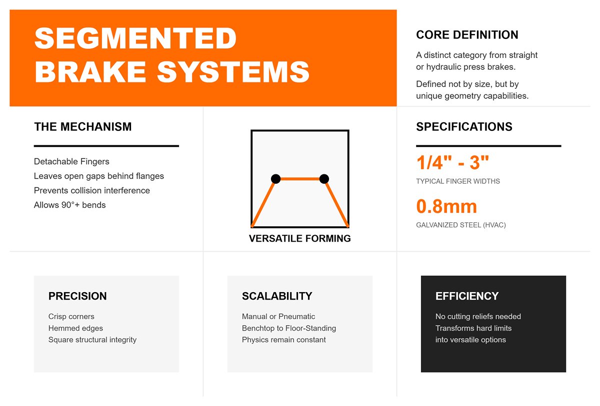
This clever approach transforms a hard mechanical limit into a versatile forming option. In HVAC shops, it produces four‑sided duct pans from 0.8 mm galvanized steel without cutting reliefs. In fabrication studios, it turns out precise aluminum boxes with hemmed edges and crisp corners. Operators simply choose finger widths—typically from ¼ inch to 3 inches—to suit the flange dimensions. After the first two bends, they remove or reposition fingers for the remaining folds, allowing the part to clear the tooling, remain square, and avoid crushed corners or warped seams.
The same principle works at any scale, from compact benchtop units to floor‑standing brakes over four feet long. Whether operated manually or with pneumatic assistance, the physics remain the same: the segmented clamping beam makes the difference. Once you grasp that feature, it’s clear why these machines belong in a distinct category from straight or hydraulic press brakes.
The confusion largely stems from how these machines are marketed. Each term spotlights a different advantage of the same underlying design. “Finger brake” underscores precision and versatility—the array of short steel segments that can be rearranged like chess pieces to form custom bending profiles. “Box and pan brake” shifts focus to the end product—the ability to fabricate boxes, trays, and pans with fully enclosed sides. “Segmented brake” points to the engineering itself: an upper clamping beam divided into sections to avoid interference with existing bends.
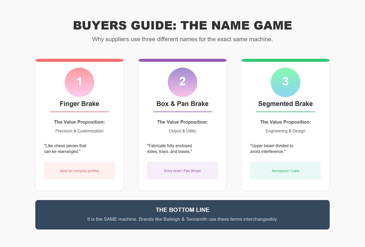
Because each name appeals to distinct buyers, catalogs, websites, and promotional materials often use them interchangeably. A small fabrication shop may purchase an entry‑level unit branded as a “box and pan brake,” while an aerospace lab orders the same chassis labeled “segmented manual brake.” Even major manufacturers blur the terminology—Baileigh, Tennsmith, and GMC all market nearly identical machines under all three names. Online discussions only compound the confusion; forum threads frequently group them with hydraulic press brakes, leading hobbyists to overspend on CNC-driven equipment designed for heavy plate rather than thin sheet metal.
Despite the naming chaos, the mechanical design is remarkably consistent. Each model incorporates a clamping leaf, an adjustable bending leaf, and a row of removable fingers fastened by thumbscrews or bolts. Everything else—the paint scheme, brand logo, foot pedal, or pneumatic assist—is merely variation on a well‑established structural geometry.
If you find yourself in a workshop wondering which type of brake you’re looking at, just examine the beam. Do you see a row of rectangular steel blocks that can be individually lifted off or unscrewed? That’s your answer. If the clamping jaw is a single unbroken bar, it’s a straight brake. The segmented—or finger—design always features those short clamping bars, often called “teeth,” which can be repositioned or removed to clear the flanges already bent on your workpiece.
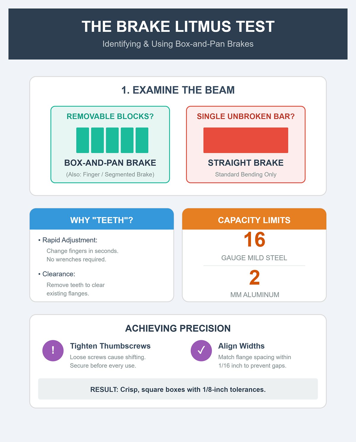
This quick visual check can save considerable time and money. Some hydraulic press brakes may claim to have “fingers,” but in reality those are heavy tooling sections built for high‑tonnage applications and not meant for rapid adjustment. A genuine box‑and‑pan brake allows finger changes in seconds, no wrenches required. That efficiency defines the manual style—swift setup, minimal force, and the delicate control needed when working with thin sheet stock.
Recognizing this distinction also safeguards your equipment. Manual box‑and‑pan brakes are built for light‑duty work—typically maxing out around 16‑gauge mild steel or about 2 mm aluminum. Forcing thicker material can twist the clamping leaf or snap hinge pins. One shop reportedly ruined a $2,000 bench brake by trying to fold 14‑gauge stock meant for a hydraulic press. The solution isn’t more muscle—it’s using the right machine for the metal’s thickness.
Accuracy depends on preparation. Aligning the finger widths with flange spacing—to within about one‑sixteenth of an inch—prevents distortion and unsightly gaps. Many operators who complain that their brake “won’t stay square” are actually dealing with loose thumbscrews that let the fingers shift during bending, throwing corners out by several degrees. Cinch them tight before every use, and the machine produces crisp, square boxes with repeatable 1/8‑inch tolerances.
Ultimately, the label isn’t what counts—the results are. Whether you call it a finger brake, a box‑and‑pan brake, or a segmented brake, each term points to the same ingenious solution to a century‑old fabrication puzzle: forming a precise, square box without defying geometry—or ruining your sheet metal.
When most metalworkers refer to a “finger brake,” they usually mean the traditional manual leaf brake—the classic box‑and‑pan design with removable steel fingers fastened to the top beam. Those fingers create clearance for flanges, sides, and corners, giving the machine its trademark flexibility to bend multiple edges without interference. Mechanically, it’s straightforward: the operator lifts a hinged leaf, causing the sheet to rotate along the joint between the leaf and the clamping bar.
The manual leaf brake shines through its simplicity. It’s compact, requires no electricity or hydraulics, and handles light‑gauge stock—typically up to 16‑gauge steel (about 1.5 mm)—with reliable accuracy in practiced hands. Its interchangeable fingers, often supplied in widths of 1″, 2″, 3″, and 4″, are held by bolts or thumbscrews and can be rearranged quickly to match the job at hand.
Common uses include fabricating HVAC ducting, electrical cabinets, and prototype chassis—tasks that call for crisp, shallow bends rather than deep-formed shapes. However, accuracy and repeatability rest entirely on the operator’s skill and consistency; bend angles or flange heights can subtly drift due to fatigue or slight misalignment. That’s why manual box-and-pan brakes excel in small, craft-oriented workshops rather than in high-volume automated lines. They’re tools for artisans, favoring precision born of patience over brute force.
From a distance, a press brake equipped with segmented tooling may resemble its manual counterpart—a row of removable sections runs the full length of the work area. But the similarity stops once bending begins. Instead of relying on human strength, hydraulic or mechanical cylinders drive the ram downward, delivering meticulously controlled force. The tooling—be it gooseneck punches or sectionalized dies—serves the same clearance function as manual fingers, yet operates on a vastly more powerful and precise scale.
While a manual finger brake tops out at around 16‑gauge steel, a hydraulic finger press brake can handle material up to 5/8″ thick at narrower widths. This leap in capacity unlocks possibilities such as heavy-duty structural components, oversized panels with intricate offsets, and the production of consistent shapes through hundreds of cycles. Contemporary CNC-controlled presses track ram position down to the thousandth of an inch, automatically adjusting for springback and tool wear to maintain uniform results.
Much of the confusion in terminology comes from this overlap. Marketing often labels these machines as “finger press brakes,” implying they are equivalent to manual box-and-pan brakes. In reality, though both use segmented clamping elements, they differ entirely in capability, force, and price range. A small three‑foot manual finger brake may cost under a thousand dollars, while even an entry‑level CNC finger press brake will run into tens of thousands. The source of power, the precision of control, and the range of material they can handle redefine them as separate categories altogether.
The key distinction isn’t in the presence of “fingers,” but in what those fingers must accomplish for your work. Start by assessing material thickness and production volume. If the bulk of your projects involves 24‑ to 16‑gauge materials in custom sizes, a manual box-and-pan brake offers unmatched adaptability for a modest investment. For one-off enclosures or ducts, the few minutes required to rearrange fingers, fine-tune gaps, and adjust the leaf angle are negligible compared to the benefits of flexible, low-cost forming.
If your work involves steel that’s 1/4 inch thick or more, parts that demand consistent bend angles, or precision components that must stack or weld seamlessly, then a hydraulic press brake with segmented tooling is essential. Its amplified tonnage delivers sharp, identical bends all day without tiring the operator. Plus, it supports digital controls, backgauges, and offline programming—transforming bending from a hands-on craft into a streamlined production operation.
One critical factor to consider is interference clearance. Both manual brakes with removable fingers and press brakes with sectional punches can manage a “fourth-side” bend that would otherwise collide with fixed tooling. On a manual brake, you pull out the fingers in areas where box walls would otherwise hit the clamp. On a press brake, segmented gooseneck punches or shorter die sections achieve the same result, allowing clearance for pre-bent flanges. The core idea is identical, though the scale, precision, and power requirements differ dramatically.
Choosing between these machines is less about their brand names or marketing claims and more about aligning their strength, precision, and operating costs with your production needs. Many shops begin with a manual box-and-pan brake for prototyping, then move on to a segmented press brake once heavy-gauge materials and repeat production become the priority. Seen in that light, they’re not rivals but sequential stages in expanding a shop’s metalworking capabilities.
The real pitfall lies in using “finger brake” as a catch-all term. Understanding the difference between a manual leaf brake and a press brake with segmented tooling can prevent costly missteps and ensure that performance expectations match reality. Once you appreciate the difference between effortless hand bends in 16‑gauge sheet and the controlled force of hydraulic folds in 5/8‑inch plate, the terminology falls into place. This isn’t just a matter of names—it’s about leverage, applied tonnage, and intended purpose.
| Feature | Manual Leaf Brake (Box-and-Pan) | Hydraulic Press Brake (Segmented Tooling) |
|---|---|---|
| Power Source | Manual (human strength) | Hydraulic or mechanical cylinders |
| Flexibility | Removable steel fingers allow clearance for flanges, sides, and corners | Segmented punches/dies provide clearance for complex shapes |
| Typical Material Capacity | Up to 16‑gauge steel (~1.5 mm) | Up to 5/8″ thick at narrower widths |
| Precision & Control | Dependent on operator skill; bend angles may vary | CNC controls enable precision to thousandths of an inch; compensates for springback/tool wear |
| Size & Portability | Compact, no electricity required | Larger footprint, requires power source |
| Common Finger Sizes | 1″, 2″, 3″, 4″ | Segments vary depending on tooling design |
| Typical Uses | HVAC ducting, electrical cabinets, prototype chassis | Heavy-duty structural components, large panels with offsets, high-volume production |
| Setup Time | Quick manual rearrangement of fingers | CNC setup and programming for consistent production |
| Repeatability | Operator-dependent; fatigue can affect accuracy | High repeatability over hundreds of cycles |
| Cost Range | Under $1,000 for small models | Tens of thousands for entry-level CNC units |
| Best For | Low-volume, custom, and craft-oriented work | Thick materials, consistent bends, and production efficiency |
| Clearance for Fourth-Side Bends | Remove fingers in collision areas | Use segmented gooseneck punches or shorter die sections |
| Common Shop Role | Prototyping and one-off projects | Production and heavy-gauge fabrication |
| Key Decision Factors | Material thickness, production volume, budget | Need for consistent precision, handling thick materials, automation potential |
Traditional leaf brakes are optimized for flat workpieces and straight bends where nothing obstructs the solid clamping beam. Problems arise once two perpendicular flanges have been formed. These upward-facing flanges protrude into the path of the descending clamp, causing direct interference. The beam’s design doesn’t accommodate such projections—on the third bend, it may pinch the flange against the blade, deform the corner radius, or even crush the material entirely.
This interference goes beyond a simple clearance issue—it’s a complex geometric challenge. Each flange introduces both width and height, reshaping the bending envelope and determining how the workpiece fits beneath the clamping beam. When performing the third bend, those corner intersections restrict insertion depth well before full seating occurs. Small compensations, like slightly overbending the first two flanges to lean them away, rarely help; the third-side clamp usually warps the box into an out-of-square form because the corners lack uniform support. In real-world use, nine out of ten standard brake attempts lose squareness at this stage unless the operator employs specialized tooling.
Segmented fingers eliminate this interference by introducing intentional voids within the clamping beam. Rather than using one continuous, solid face, the beam features a series of removable hardened steel segments—each precisely machined, typically between 1 and 4 inches wide. By taking out selected segments, the operator creates areas of “negative space” where pre-formed flanges can pass freely. When clamped, these flanges settle neatly between the fixed fingers, allowing the bending blade to engage only the unformed sections of the sheet.
This configuration offers far more than simple clearance. When properly arranged, those gaps become self-aligning guides. As the flange slides into a void, it automatically locks the workpiece parallel to the bending axis—preventing the rotational drift that often twists corners in box fabrication. Finger placement thus becomes an integral part of setup: position one finger tight against the edge to be bent, leave precisely one material thickness of space between it and the folding blade, and fill the remainder of the beam with fingers sized to suit. The outcome is repeatable bend geometry and consistent alignment from part to part. Seasoned fabricators also note that limiting unused gaps to under two finger-widths on light-gauge stock helps maintain uniform clamping pressure and minimizes beam deflection.
The finger press brake’s ability to eliminate flange interference revolutionizes everyday workshop operations. In HVAC fabrication, for instance, sheet metal trays and covers often feature 3 to 4-inch side walls, typically hemmed to remove sharp edges. Finger clearance enables those hems to be formed right from the first bends and ensures all four sides can be finished smoothly without damaging the flanges. The result is a major reduction in prototyping time compared with switching over to a standard press brake.
In commercial kitchen manufacturing, pans and trays made from 22-gauge aluminum take full advantage of the hem-and-bend technique while preserving their delicate surfaces. The segmented finger arrangement lets the completed hems fit snugly into the clamping gaps, producing seamless, leak-resistant joints straight off the brake.
Electronics enclosure production often calls for quick width adjustments during short-run jobs. Employing the “Tetris” method—selecting finger widths to match flange positions—operators can create boxes of different sizes without reprogramming or swapping lower dies. Industrial examples include the Baileigh BB-12016, equipped with a range of finger widths to handle large-format enclosures in 16-gauge mild steel, capable of bending up to 135° to simplify assembly.
Experienced sheet metal workers recognize the leap in precision. Ron Fournier’s classic demonstration vividly illustrates the difference between a standard 48-inch brake and a finger brake on light-gauge aluminum: the finger brake produces a perfectly square, true-sided box in just four bends, whereas the standard brake buckles the third side upon first contact with an existing flange.
Shop reality check: Finger brakes are best suited for light to medium materials—up to around 2 mm in mild steel. Beyond 16-gauge, manual leverage becomes impractical, and hydraulic presses or heavier tools are required. Equally critical is proper clamping technique: loose fingers can twist under pressure on thin sheets, so eccentric clamps and locknuts must be tightened firmly to maintain precision.
Envision segmented fingers like the missing pieces in a jigsaw puzzle. On a standard brake, the “puzzle” is complete—there are no gaps, so protruding flanges have nowhere to fit. A finger brake changes the game: you remove selected pieces to create custom-shaped gaps that accommodate those pre-formed flanges perfectly. This deliberate absence is what makes it possible to shape complex, multi-dimensional parts without collision, distortion, or wasted effort. The mindset shift is key: instead of asking, “How do I get past this obstruction?” you ask, “Where should this obstruction be absorbed?” With that approach, the machine adapts to the workpiece, rather than forcing the workpiece to adapt to the machine.
The art of arranging fingers is where theory meets hands-on precision. Each hardened steel finger, available in graduated widths, is a modular component for defining your bend line. The operator’s task feels like solving a spatial puzzle—mixing narrow and wide segments to match flange depth while leaving clearance for previously bent edges. For instance, when fabricating a box with 5-inch sides, an ideal layout might be two 1-inch fingers paired with a 3-inch finger per section, allowing space that prevents distortion as the final side is folded into place.
Here’s where the trade-off appears. Wider fingers spread clamping pressure more evenly—a real advantage with thicker or higher-strength metals—but they also limit the minimum flange depth you can achieve. Slotting in a 3-inch finger means the adjoining flange must be at least that wide, or you’ll face interference issues. Many hobbyists mistakenly invest heavily in narrow fingers, assuming smaller means more precision. In reality, the reduced contact area often slips when working with 14-gauge or heavier stock under full bending force.
Experienced shops sidestep this problem by sorting finger trays before starting a job. Organizing fingers by width—rather than leaving them jumbled in the brake’s drawer—transforms a complicated setup from a twenty-minute trial-and-error process into a consistent five-minute routine. This small adjustment pays off exponentially in batch work. True workflow efficiency begins at the workbench, turning setup from reactive problem-solving into a confident, predictable calibration step.
Many technicians mistakenly believe that the spaces between brake fingers are harmless gaps. In truth, those openings directly influence the brake’s structural stability during bending. Every gap reduces the available clamping area, and if the opening exceeds half the sheet’s thickness, the material can flex into it and slip when torque is applied. The outcome is inconsistent bend radii or even full release—errors often mistaken for friction issues rather than poor setup. For instance, in 16‑gauge steel, leaving just a 1/8‑inch gap can result in roughly one‑third of panels being rejected due to corner twisting or hem distortion.
Even when gaps are eliminated, setups can fail if finger heights aren’t perfectly level. A variation as small as 0.01 inch between segments causes uneven clamping pressure, twisting edges by two to three degrees. In precision applications—such as electronic enclosures, HVAC housings, or architectural panels—these distortions accumulate across assemblies. The fix is straightforward: after locking the fingers, test with a scrap sheet held under static pressure for about ten seconds. If you detect more than 1/32 inch of movement, add shims under the lower fingers or replace mismatched ones. This small, consistent check turns basic positioning into dynamic calibration, ensuring even clamping force along the entire line.
The real reason corners warp isn’t the bend angle—it’s the uneven finger height caused by improper truss rod tensioning. When the clamping beam tilts—gripping one side tightly while leaving the other loose—the pressure concentrates locally and pulls corners inward. This distortion often goes unnoticed until final assembly, when boxes fail to square by one or two degrees. Many initial production runs are scrapped before the underlying pattern becomes clear.
The problem stems from setting clamp pressure by sight instead of checking actual gap depth. The correct approach is to set clearance at twice the material thickness to accommodate the bend radius and elastic recovery. Over‑tightened rods compress fingers unevenly, amplifying beam rocking. After setup, lay a straightedge across the engaged fingers; a uniform shadow beneath it indicates proper alignment. If light passes through more than half the span, re‑adjust the truss rods from the center outward until even. Precision shops using this method routinely cut corner distortion to under half a degree.
Industrial production lines sometimes try to disguise the issue using a two-stage pre-bend—first forming to roughly 135 degrees, then pressing flat during final closure. While this may temporarily mask the floating-end effect, it merely transfers the distortion into residual stress along the fourth panel. With time, that hidden tension surfaces as micro‑cracks or misaligned assemblies. Genuine precision doesn’t come from corrective tricks—it comes from achieving perfect geometric alignment during the initial setup.
The Unexpected Insight: Most technical manuals describe finger presses as fixed tools, focusing on geometry while overlooking workflow rhythm. In practice, consistency stems from a well-choreographed process rather than hardware itself. Work with a “dry-fit” mindset—configure fingers for the next build while still completing the current one. That visual overlap highlights alignment errors, worn segments, and clearance mismatches before the material ever meets the clamp.
Think of the brake as a unified force system rather than a collection of components. Each finger’s placement alters the load path and dictates the minimum flange geometry. Log the finger maps that yield clean bends for standard box sizes, and make note of any setups that fail with high‑strength alloys. Over time, the operator who records these fine adjustments builds a reliable playbook—one that consistently outperforms intuition alone. This disciplined approach, not brute capacity, is what separates repeatable production accuracy from lucky prototypes.
A finger press brake’s real bending limit isn’t simply the rated “maximum gauge”—it’s the balance between material thickness, bend length, and operator leverage. Manual box‑and‑pan brakes generally top out around 16‑gauge mild steel (about 1.6 mm or 1/16″), as anything thicker overwhelms both human effort and beam rigidity. Push beyond this range, and the top beam begins to flex or the clamping bar distorts, permanently compromising precision.
Capacity ratings can be misleading because they depend heavily on bend length. A DIY brake that boasts the ability to bend 5/8″ mild steel may only achieve that across a very narrow section—perhaps just three inches—since tonnage requirements increase directly with bend length. Industrial bend charts clarify this: bending 1/4″ (6.35 mm) mild steel using a die with an 85–90° V‑opening demands about 15 tons per foot. Extend that to a 3‑foot bend, and you’ll need three times the force. In practice, many so‑called “20‑ton” small hydraulic presses either stall or flex when asked to form 1/4″ steel over more than one or two feet, no matter how sturdy they appear on paper. Recognizing this proportional scaling early on helps you choose a brake that matches not only your target material thickness but also the full range and dimensions of the parts you intend to fabricate.
While bed length sets the upper limit of bending span, it’s the width of each finger segment that truly defines how adaptable the brake is. Every finger must be narrower than your smallest internal flange, or it will collide with adjacent sections during multiple bends. A simple guideline: finger width should be equal to or less than the box depth plus the material thickness. Go any wider, and you’ll find yourself unable to close boxes properly—leaving gaps that distort edges and compromise precision.
Take the example of forming a 4″‑deep box from a 12″ blank. You might need six fingers between 1.5″ and 2″ wide to span the center area cleanly, with filler fingers to complete the full width. Without a sufficient selection of narrow segments, you’ll face awkward compromises—either removing fingers and risking end deformation, or using fingers too wide, which can mar or twist the metal. As a result, many operators discover that their “full‑width” brake provides less real flexibility when working with varied box depths. Industrial‑grade brakes overcome this through modular sectional tooling that can be reconfigured, but the lesson remains the same: always have enough narrow tooling segments to handle your most demanding box geometries.
Throat depth—measured from the clamping line to the rear frame or any obstacle—quietly determines the tallest box you can form. In most manual brakes, this depth ranges from 4″ to 10″, restricting how far you can bend deep enclosures. The limitation becomes critical when working on the third and fourth sides of a box: the throat must clear previously formed flanges. Practically, that means it must be greater than the flange height plus at least twice the material thickness if you want return bends to go smoothly.
Ignoring throat depth often leads to jobs stalling mid‑bend when a formed edge collides with the machine frame. Even heavy‑duty industrial brakes are not immune—thicker materials demand wider die openings (typically eight times the material thickness for mild steel), which effectively shrink the available throat clearance. A shop investing in a 14‑foot bed for fabricating tall HVAC pans might discover that a 10″ throat falls short for an 8″‑deep side, resulting in redesigns or the need to outsource. Because most manufacturers highlight bed length and tonnage over throat depth, you need to dig for this spec yourself—otherwise it becomes the hidden limitation that derails your bending process.
Most buying guides gloss over these constraints, summarizing capacity with vague claims like “bends 12‑gauge steel” or “full‑width forming.” In truth, tonnage dictates available force along the bed, finger width shapes your internal geometry, and throat depth sets the ceiling for box height. These aren’t secondary details—they determine whether your brake can actually produce the parts on your drawings without workarounds, retooling, or wasted material.
By viewing a brake’s capacity through the lens of these three interdependent dimensions, you can avoid common setup failures: stalled bends, warped corners, or unfinished boxes caused by simple physical constraints. Mastering how these specifications interact transforms the brake from a generic forming tool into a finely tuned asset—one that channels your precision and technique into repeatable, efficient, distortion‑free results.
The first benchmark for any quality finger brake is whether it can maintain its position under pressure. Cam‑lock clamping systems excel in agility—allowing you to rearrange fingers in seconds without tools or effort. For shops handling custom one‑off jobs, that flexibility is invaluable. You can reset configurations between tasks faster than the previous part cools from its bend. Yet, that same speed carries a compromise: lightweight cam‑locks tend to slip when challenged with materials beyond 14‑gauge steel, causing slight alignment shifts and shaving a few degrees off accuracy. It’s not a matter of operator skill—it’s simply the friction‑and‑torque limits of the design.
In contrast, bolt‑down systems trade speed for staying power. They aren’t quick, but they hold with the uncompromising grip of a vise. Industrial presses may take longer to adjust, yet every bolt secures the tooling firmly against the backing bar so that even under loads reaching thousands of tons, deflection is nearly eliminated. Across countless cycles, that rigidity pays dividends—tolerances remain within half a degree, and the machine’s core structure doesn’t loosen with age.
If your workflow revolves around short runs—design labs, HVAC prototypes, or custom electrical enclosures—the cam‑lock delivers swift setup and efficient handling for lighter materials. But once repetitive production enters the picture, rigidity becomes synonymous with cost‑effectiveness. A finger brake that saves minutes during setup but sacrifices precision in output isn’t efficient—it’s expensive. Start by counting your daily setup changes: five or more? Choose cam‑lock. Fewer? Go with bolt‑down and enjoy lasting accuracy.
Precision doesn’t vanish suddenly—it erodes from within. Soft steel fingers on hobby‑grade brakes (around 200–300 Brinell) slowly deform under repeated use. Each bending cycle leaves a microscopic indentation where metal meets metal. After several hundred sheets, those marks accumulate, leading to misaligned flanges, drifting corners, and boxes that no longer fit their lids. What may appear purely cosmetic is actually incremental deformation—tiny shifts compounded across every edge of every component.
Industrial‑grade brakes tackle that wear by using hardened tooling rated between 50 and 60 Rockwell C. This level of toughness doesn’t just resist indentation—it prevents the equipment from developing mechanical drift. Facilities turning out tens of thousands of aluminum trays report years of consistent performance before any maintenance is necessary. One operator recorded 50,000 cycles with less than five thousandths of deflection—clear evidence that the fingers remained more stable than the surface they sat on.
Here’s the rule that separates tools built to last from those destined to fail: run a test strip of 14‑gauge mild steel. If the finger teeth leave marks deeper than 0.005 inches, the steel’s already too soft. Replace or upgrade before precision loss turns into scrap waste. It’s a quiet step that prevents hundreds of dollars in ruined parts and hours of rework—and often marks the point where hobby-grade equipment crosses into true industrial reliability.
Finger brakes are tempting—they look adaptable, practically modular, as if they could handle any shape you dream up. In reality, that flexibility only pays off when your work involves clearance bends or fully enclosed boxes. If your projects are flat or fold along a single axis, a straight leaf brake will outperform every time. It delivers consistent pressure, cleaner results, and no need to juggle finger setups or fight with uneven flanges.
The guideline is straightforward: if your bends run longer than 48 inches, less than four inches deep, and you’re producing under 50 parts a month, go with a straight brake. It keeps each cycle fast, smooth, and repeatable—reducing setup time by as much as 80%. Finger brakes only take the lead when you must isolate and lift panels that a fixed leaf would crush—like electrical boxes or four‑sided housings hemmed on every edge.
Overbuying is the hidden tax of the hobbyist upgrade. Investing thousands in finger brakes when your projects call for flat bends slows production and siphons funds away from tooling that would actually boost throughput. Every experienced fabricator learns this lesson eventually: in forming, the best machine isn’t the one with the most pieces—it’s the one that gets the job done with the fewest moves and the most consistency.
The best brake is the one that moves at your pace. Count your setups. Check the teeth. Trace the bend lines. When precision aligns with workflow, you’ll see why industrial machines last for decades—and why, more often than not, the smartest choice is the simple leaf brake quietly waiting on the shop floor.


