

He’s got the calipers in one hand and the part in the other. First leg is 0.750″. Second leg is 0.782″. Offset’s supposed to be 0.500″; he’s reading 0.468″. So he bumps the backgauge two thou, feathers the pressure, runs another. Closer. Still off.
By the fifth tweak he’s blaming himself.
But nothing about that scene is a technique failure. It’s math. And it starts the moment you flip the part.
You’re forming a Z with a standard V-die. First bend down. Pull the part out. Rotate 180 degrees. Re-gauge. Second bend up. Two separate air bends, two separate setups, two separate opportunities for variation.
Air bending means the angle is controlled by depth. Depth is controlled by the hammer’s position. Position is influenced by material thickness variation, grain direction, springback, and machine deflection. You already know that.
What you may not be accounting for is this: when you flip the part, the second bend references a surface that was just created by the first bend. Any angle error, any flange length variation, any slight bow becomes the foundation for the second operation.
That’s not correction. That’s compound interest.
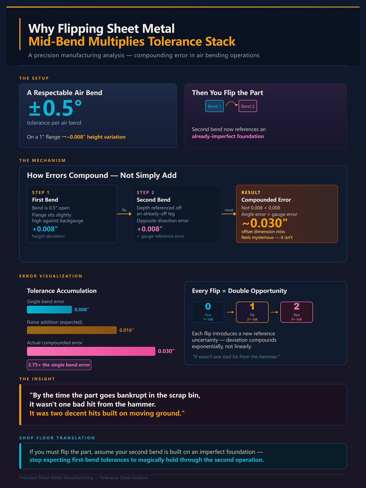
Let’s walk a simple hypothetical. You’re holding ±0.5° on each air bend. That’s respectable. On a 1″ flange, 0.5° is roughly 0.008″ of height variation. Now flip the part.
If the first bend is 0.5° open, the flange sits slightly high against the backgauge on the second setup. Now your second bend depth is referenced off a leg that’s already off. If that bend is also 0.5° off—maybe in the opposite direction—you’ve stacked angle error plus gauge reference error.
You didn’t add 0.008″ and 0.008″. You compounded them. And when the offset dimension misses by 0.030″, it feels mysterious.
It isn’t.
Every flip doubles the opportunity for deviation. By the time the part “goes bankrupt” in the scrap bin, it wasn’t one bad hit from the hammer. It was two decent hits built on moving ground.
Shop Floor Translation: If you must flip the part, assume your second bend is built on an imperfect foundation—so stop expecting first-bend tolerances to magically hold through the second operation.
So if stacking is baked in, what is it costing you besides rework?
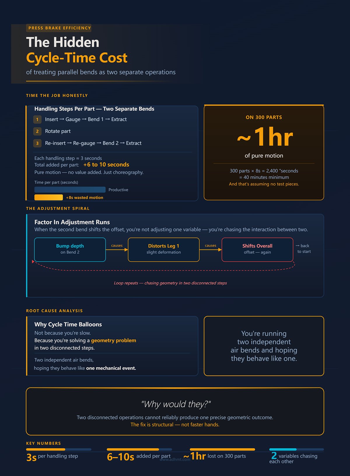
Time the job honestly. Bend one: insert, gauge, hit. Extract. Rotate. Reinsert. Re-gauge. Hit. Extract again.
Even if each handling step takes three seconds, you’ve added six to ten seconds per part. On 300 parts, that’s nearly an hour of pure motion—no value added, just choreography.
And that’s assuming no test pieces.
Now factor in adjustment runs. Because when the second bend shifts the offset, you’re not adjusting one variable—you’re chasing the interaction between two. So you bump depth on bend two, which slightly distorts leg one, which shifts your overall offset again.
Cycle time balloons not because you’re slow, but because you’re solving a geometry problem in two disconnected steps.
You’re running two independent air bends and hoping they behave like one mechanical event.
Why would they?
Picture a stepped die set designed so both bends form simultaneously. The punch and lower die are matched so the material is captured and driven into fixed geometry in one downward movement of the hammer. No flip. No second reference. No re-gauging off a bent leg.
Both angles happen at the same time, locked by tooling geometry, not depth guessing.
That’s what “one stroke” promises: eliminate the second setup, eliminate the second reference surface, eliminate the compounding.
Now here’s why shops hesitate. Offset dies demand matched punches. They often require bottoming, which means higher tonnage than casual air bending. Thickness has to match the die spec. Stainless and aluminum still need over-bend allowance for springback. You don’t get to be sloppy.
So operators look at the force chart, look at their standard V-die routine, and think this is specialty tooling for rare jobs.
But ask yourself: are your Z-bend misses really about hand skill—or about trying to make two separate air bends behave like a single rigid system?
You’re staring at the tonnage chart. Mild steel. 10 gauge. 1″ V-die says you need roughly X tons per foot using the standard formula: P = 650 × S² × L / V.
You’ve run that math a thousand times. It works—because it assumes one thing: a single V opening, uniform contact, air bending. Three points of contact. Depth controls angle.
Now you drop in an offset die. Stepped cavity. Matched punch. Two shoulders. And you’re still looking at that same formula like it applies.
That’s where guys get hurt—or at least surprised.
Because an offset die is not a specialty V-die. It’s a rigid mechanical trap. And the moment you treat it like air bending, you’re solving the wrong physics problem.
If one stroke eliminates stacking and re-referencing, then what are the trade-offs? Force. Flexibility. Sensitivity. That’s what we’re about to tear apart.
Set a piece of 14 gauge across a stepped die and bring the hammer down slowly in setup mode. Watch closely.
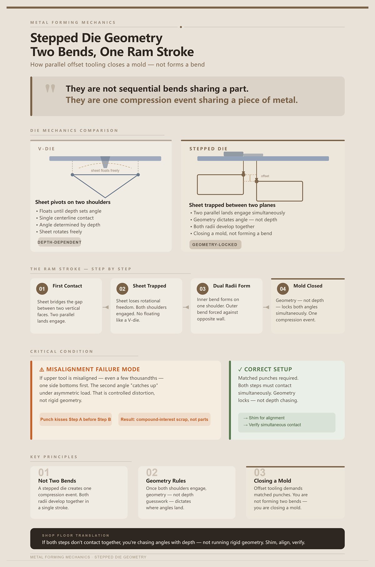
First contact doesn’t happen at one centerline like a V-die. It happens across two parallel lands. The material bridges a gap between two vertical faces in the lower die. The punch nose isn’t aiming for the bottom of a V; it’s driving the sheet into a pocket with a fixed offset height.
As the hammer continues down, the sheet can’t rotate freely the way it does in air bending. It’s trapped between two planes. The inner bend begins to form on one shoulder while the outer bend is already being forced against the opposite wall. The two radii develop together.
That’s the key: they are not sequential bends sharing a part. They are one compression event sharing a piece of metal.
In a V-die, the sheet pivots around two lower shoulders and floats until depth sets angle. In a stepped die, the sheet loses that freedom almost immediately. Once both shoulders engage, geometry—not depth guesswork—dictates where the angles must land.
But only if the punch hits both steps at the same time.
If your upper tool is misaligned by even a few thousandths, one side bottoms first. Then the second angle “catches up” under asymmetric load. That’s not rigid geometry anymore—that’s controlled distortion. I’ve seen operators blame material when the real issue was the punch kissing one step before the other.
That’s when parts start going compound-interest on you and eventually file bankruptcy in the scrap bin.
This is why offset tooling demands matched punches and careful setup. You’re not forming two bends. You’re closing a mold.
Shop Floor Translation: If both steps don’t make contact together, you’re not running a rigid system—you’re back to chasing angles with depth. Shim, align, and verify simultaneous contact before you trust the result.
So if geometry locks both angles at once, why can’t you use air-bend tonnage logic to size the job?
Run the same 10 gauge mild steel in a 1″ V-die air bend. The sheet touches at three points: two shoulders and the punch tip. The center of the sheet never sees full die-face contact. You’re bending, not crushing.
Now take a tight offset die—say a 0.375″ step. That lower cavity is narrow. The material is driven fully into the die profile. Contact area increases dramatically as the hammer finishes the stroke. You are no longer in three-point bending. You are bottoming into a fixed shape.
That changes everything about force.
The standard formula assumes tensile strength around 450 N/mm² and uniform V geometry. It does not account for dual radii forming simultaneously, nor for the localized compression at the step corners. Smaller step heights mean tighter radii. Tighter radii shift the neutral axis inward and spike localized stress.
That’s why you’ll sometimes see 20–50% higher peak force on a tight offset than the V-die chart predicted—even though the part “looks small.”
Operators think, “It’s a little Z. Should be easy.” Then the tonnage meter jumps.
Because you’re not bending across a wide V. You’re squeezing material into two confined corners at once.
And here’s the trap: total tonnage per foot might still be lower than a large V opening job, but peak force at the moment of bottoming is higher and sharper. If you size the job off air-bend math, you risk either under-forming—or overloading the setup.
Different physics. Different contact. Different stress map.
This is not depth-controlled angle anymore. It’s die-controlled geometry under compression.
Shop Floor Translation: Stop using V-die air-bend charts for offsets. Check bottoming tonnage for the specific step height and material, and expect higher peak force on tight offsets—even when the part looks small.
If we’re bottoming into fixed geometry, though, where does the second angle actually originate? Is the die creating it—or is something else happening inside the metal?
| Section | Content |
|---|---|
| Title | Bottoming vs. Air Bending: Why Offset Profiles Require a Completely Different Physics Model |
| Air Bending Scenario | Run the same 10 gauge mild steel in a 1″ V-die air bend. The sheet touches at three points: two shoulders and the punch tip. The center of the sheet never sees full die-face contact. You’re bending, not crushing. |
| Offset Die Scenario | Take a tight offset die—say a 0.375″ step. The lower cavity is narrow. The material is driven fully into the die profile. Contact area increases dramatically as the hammer finishes the stroke. You are no longer in three-point bending. You are bottoming into a fixed shape. |
| Force Implications | This changes everything about force. |
| Standard Formula Limitation | The standard formula assumes tensile strength around 450 N/mm² and uniform V geometry. It does not account for dual radii forming simultaneously, nor for localized compression at the step corners. |
| Stress Behavior | Smaller step heights mean tighter radii. Tighter radii shift the neutral axis inward and spike localized stress. |
| Peak Force Reality | You may see 20–50% higher peak force on a tight offset than the V-die chart predicted—even though the part looks small. |
| Operator Assumption | Operators think, “It’s a little Z. Should be easy.” Then the tonnage meter jumps. |
| Root Cause | You’re not bending across a wide V. You’re squeezing material into two confined corners at once. |
| Hidden Risk | Total tonnage per foot might still be lower than a large V opening job, but peak force at bottoming is higher and sharper. Sizing the job off air-bend math risks under-forming or overloading the setup. |
| Physics Difference | Different physics. Different contact. Different stress map. |
| Process Classification | This is not depth-controlled angle anymore. It’s die-controlled geometry under compression. |
| Shop Floor Translation | Stop using V-die air-bend charts for offsets. Check bottoming tonnage for the specific step height and material. Expect higher peak force on tight offsets—even when the part looks small. |
| Open Question | If we’re bottoming into fixed geometry, where does the second angle actually originate? Is the die creating it—or is something else happening inside the metal? |
Take a cutaway view in your head.
As the punch drives down, the inner bend forms first because it has the smaller effective radius. The outer leg is still relatively flat. Then the material between the two steps starts to compress longitudinally. It has nowhere to go but into curvature.
The second angle doesn’t magically appear because the die has two corners. It develops because the center web of the offset is being shortened under compression while both legs are constrained by vertical walls.
That constraint is everything.
In air bending, the outer fibers stretch and the inner fibers compress around a single neutral axis. In an offset die, you’re creating two bending zones separated by a short web. That web is forced into shape as the legs bottom against their respective planes. The second angle is born from the web being trapped and shortened between two fixed boundaries.
If material thickness varies, that web length changes. If the punch contacts one step first, the web distorts asymmetrically before full compression. That’s why thickness tolerance matters more here than in casual air bending.
This is also why offset dies feel “inflexible.” They are. Geometry is predetermined. If your material deviates too far, the system doesn’t adjust—it fights back.
And that rigidity is the whole point. It eliminates tolerance stacking because both angles and the offset height exist in the same mechanical event under the same stroke of the hammer.
One compression. Two bends. No re-reference.
The price is that you’ve abandoned the forgiving nature of air bending. You are now running a fixed mold under load.
So the next question isn’t whether offset dies eliminate stacking—they do. The real question is how to calculate and control that compression event without lying to yourself with V-die math.
A few years back we quoted a job: 10 gauge mild steel, 0.375″ offset, 4 feet long. Operator grabbed the air-bend chart, ran the standard formula, figured roughly what that 1″ V-die would take, and added the usual 4× for bottoming. Machine said we were safe.
First hit, the hammer came down, tonnage meter spiked harder than expected, and the upper tool flexed enough to leave a witness line across both steps.
But nothing about that scene is a technique failure.
It was math. Wrong model, wrong multiplier.
Standard air-bend charts assume three-point contact in a V opening. Even when they tell you to multiply by four for bottoming, they’re still thinking about a single bend line collapsing into a V. Offset tooling is two radii forming simultaneously inside a confined cavity. The contact area increases rapidly at the bottom of stroke, and the stress isn’t distributed across a wide V—it’s concentrated at two step corners and a compressed web.
If you calculate offset tonnage like a 90-degree air bend, you are underestimating force by a multiplier that isn’t linear and isn’t optional. So let’s put numbers to it.
Take that same 10 gauge mild steel.
Air bending in a 1″ V, you run the common formula:Tonnage per foot ≈ 650 × (S² / V)
You know the drill. Square the thickness, divide by die opening, multiply by length. It works because the sheet only contacts at three points. The center spans air.
Now move to a standard offset die with a tooling factor published at 5.0 for typical offsets—and up to 10.0 for tighter or thicker combinations. That’s not a rounding error. That’s a different animal.
If your air-bend calculation gave you 20 tons total, a 5× offset factor puts you at 100 tons. If the job creeps into thicker material and the factor jumps to 10×, you’re staring at 200 tons. Same material. Same length. Completely different force profile.
Why the jump?
Because in air bending, force rises gradually as the hammer descends. In offset bottoming, force ramps sharply at the end of stroke as the material is driven fully into two opposing corners and the web between them shortens under compression. You’re not just overcoming tensile strength—you’re plastically compressing and trapping material between fixed walls.
The multiplier isn’t “exponential” in the mathematical sense. It’s stepwise and thickness-dependent. Small offsets in thin sheet might live around 5×. Tight steps in thicker stock can live at 8× or 10×. That non-linear jump is why generic bottoming advice—“just multiply air bend tonnage by four”—is incomplete for offsets. Four gets you in the neighborhood for a single 90. It leaves you short for a dual-radius compression system.
Miss that, and the scrap bin doesn’t fill with bad parts first. It fills with cracked tooling.
Shop Floor Translation: Take your normal air-bend tonnage, then apply the offset tooling factor (5× as a baseline, higher for thicker or tighter steps). If the machine rating doesn’t comfortably clear that number, don’t run it.
So if force scales with thickness and step tightness, what dimension actually controls how violent that compression event becomes?
Pull an offset die catalog and look at how they list it: step height, throat depth, sometimes recommended thickness range. What’s buried in small print is the relationship between step height and material thickness.
Run 0.125″ material in a 0.250″ step. You have room. The web between bends is long enough to form without extreme shortening. Now try 0.187″ material in that same 0.250″ step. The web is barely longer than the thickness itself. When the hammer closes, that center section has almost nowhere to go but into severe compression.
That’s when tonnage spikes beyond what your “5×” rule predicted.
As thickness approaches step height, you’re increasing the percentage of material that must plastically compress rather than simply bend. The neutral axis shifts, inner radii tighten, and contact area against the vertical walls grows sooner in the stroke. Force ramps faster and peaks harder.
And here’s where operators get blindsided: two jobs with the same offset dimension can require radically different tonnage because one is 14 gauge and the other is 10 gauge. The offset looks identical on the print. The compression physics are not.
This is also where you drift into custom-tool territory. If the job demands a step height barely larger than thickness, you’re outside comfortable standard ranges. Special tooling, higher tonnage ratings, and very little forgiveness.
Ignore that relationship and you’re basically compounding risk like interest—each increase in thickness adds more compression demand until the part goes bankrupt in the scrap bin.
Shop Floor Translation: Don’t just match the offset dimension on the print. Check that step height is comfortably larger than material thickness, or expect a steep tonnage increase beyond the basic offset multiplier.
But how tight can you really push that step before you’re not forming anymore—you’re cutting?
Imagine a 0.125″ thick sheet going into a 0.130″ step.
On paper, it fits. In reality, you’ve left almost no clearance for material flow. As the hammer bottoms, the vertical faces of the die and punch approach shear-clearance territory. Instead of controlled plastic deformation, you’re forcing metal against near-parallel walls with minimal escape.
That’s when you see shiny burnished lines at the corners. Not stretch marks—compression polishing. Push harder and you’ll get edge cracking along the inside of the step because the material can’t redistribute strain; it’s being pinched.
At some point, an offset die stops behaving like a forming tool and starts behaving like a very dull shear. The tighter the clearance relative to thickness, the closer you are to that line.
There isn’t a universal number because material strength, radius design, and die finish all matter. But the mechanism is consistent: when clearance approaches sheet thickness with no allowance for flow, tonnage spikes sharply and damage risk rises. That’s not “extra safety margin.” That’s a geometry problem.
So when you calculate tonnage for offsets, you’re not just asking, “How much force to bend this?” You’re asking, “How much force to compress and trap this without crossing into shear conditions?”
That’s a different question than any V-die chart was built to answer.
Shop Floor Translation: Maintain meaningful clearance between material thickness and step geometry. If the step is only a few thousandths larger than thickness, expect shear-like behavior and extreme tonnage—back off or redesign before you bring the hammer down.**
And once you accept that the math is multiplier-driven, thickness-sensitive, and clearance-critical, the next problem isn’t theory anymore—it’s how the machine itself must be set up to survive that compression event.
Last year I watched a 135‑ton brake try to form a 0.375″ offset in 10‑gauge across 6 feet. Air‑bend math said it was comfortable. The hammer hit, the load meter jumped past 110 tons halfway down, and by the time it bottomed the machine was flirting with its limit. The angles were dead on. The machine wasn’t.
That’s the question you’re really asking: how do you set up and rate the brake so the compression spike doesn’t punish the iron?
First leg is 0.
With an offset die, depth is not a float. It’s the dimension. In air bending, 0.010″ of ram adjustment might swing you half a degree and you trim from there. In a fixed‑geometry offset, 0.010″ is the difference between “both radii fully seated” and “one radius half‑formed while the other is crushing.” You’re not chasing angle. You’re closing a mechanical system until it stops.
Here’s the mechanism. The punch enters, contacts both bend lines, and as the hammer continues down, material is forced into two radii while the web between them shortens in compression. Force ramps slowly, then spikes when both radii contact their vertical walls. That spike happens in the last few thousandths. If your shut height is guessed, not set, you’ll either under‑form (two soft angles) or over‑drive into shear territory.
So setup starts backwards from air bending:
If you treat depth like a suggestion, tolerance stacks like compound interest—each thousandth adds compression demand until the part goes bankrupt in the scrap bin.
Shop Floor Translation: Rate the job at 5×–10× air‑bend tonnage, verify the brake can carry it across the full length, and set ram depth to full die closure—not past it. You are closing a mold, not tuning an angle.
Now that the hammer position is non‑negotiable, what edge are you even referencing from?
Picture a 1″ flange feeding into a 0.500″ offset. Operator gauges off the outside edge, runs the stroke, and the offset dimension drifts ±0.015″ across parts. Machine repeatability checks out. Tooling is solid. So what moved?
The reference edge did.
During offset forming, the web between bends shortens under compression. Not elastically—plastically. The material physically gets shorter between those two bend lines. If you gauged from the outside flange edge, that edge is no longer in the same spatial relationship to the second bend line once compression happens.
In a flip‑and‑rebend world, you’d blame technique. But nothing about that scene is a technique failure. It’s geometry.
For critical offsets, gauge from the feature that does not move under compression—usually the first bend line location or a pre‑cut datum. On edge offsets (think die sets that warn against forming within 1″ of sheet edges), spreading at the unsupported edge exaggerates this shift. That’s why back‑up leaders exist on certain offset dies: they restrain lateral spread so your reference doesn’t walk.
Spring‑up style offset tooling complicates this further. Because it keeps the sheet more horizontal and reduces thrust, large sheets don’t tilt as much—but that also means your backgauge fingers must support consistently across the width. Any tilt during approach changes effective gauge distance before the hammer ever touches metal.
So the rule becomes simple and strict: gauge from a datum that survives compression, and support the sheet so it can’t pivot under the approach load.
Shop Floor Translation: Don’t gauge off the free flange of an offset. Gauge from the bend line or a stable datum, and support the sheet so compression can’t shift your reference before bottoming.
If depth is fixed and reference is stable, what do you do when the angle is still off?
I’ve seen guys slide 0.005″ shims behind reversible offset blocks to “dial in” angle. It works—until it doesn’t.
Here’s why. In some adjustable offset systems, rotating blocks change radius and shims tweak effective depth. But every shim changes the relationship between punch nose, step height, and vertical walls. You are no longer closing a designed geometry; you’re inventing one.
Because the step height is the web dimension, even a 0.005″ shim effectively alters how much compression the web must absorb before both radii seat. That shifts the force peak. On a tight clearance job, that tiny shim can push you from full forming into near‑shear contact on one side first. Now one radius bottoms before the other, and you’ve reintroduced the very tolerance stacking offset tooling was supposed to kill.
If the angle is off:
The more you treat shims like seasoning, the more your setup drifts from fixed‑geometry behavior into custom chaos. And chaos is expensive.
Shop Floor Translation: Fix depth and material variables first. Shim only as a controlled geometry adjustment—and understand you are changing compression, not just angle.
If shimming changes compression, what happens when the part runs 8 feet long?
Run a 96″ offset in 7‑gauge and watch the load meter. The peak doesn’t spread evenly like a wide V‑die air bend. It concentrates where both radii contact hardest—usually center first as the bed deflects.
Air bending tolerates a little deflection because angle floats with depth. Offsets don’t. If the bed sags 0.010″ in the center, that center may not fully seat while the ends do—or the opposite, depending on crowning. Remember: depth is the dimension.
Standard crowning logic still applies—counteract bed deflection to achieve uniform penetration—but your margin is thinner. Because force spikes at bottom, you need crown set so full closure occurs simultaneously across the length. Too little crown and the center under‑forms. Too much and the center over‑compresses first, spiking tonnage locally.
Spring‑up tooling reduces lateral thrust, which helps with large sheets, but it does not eliminate vertical deflection. The hammer still sees the same compression event when both radii seat.
So for long offsets:
Because once you’re running, there is no “angle trim” stroke to save you.
Get this wrong and the parts won’t drift gracefully out of spec. They’ll look fine at the ends and lie to you in the middle—until assembly calls.
Shop Floor Translation: Crown for the peak offset load, not air‑bend numbers, and verify full‑length closure before production. Offsets demand uniform bottoming across the bed.
Depth is fixed. Reference must be stable. Shims change compression. Crown must match peak load.
Ignore any one of those, and the next section won’t be about fine‑tuning.
It’ll be about failure patterns.
Last winter we ran a 0.375″ offset in 10‑gauge mild steel, 72″ long. Tonnage chart said we were safe. Depth was dialed. Crown was set for the calculated peak. First three parts looked clean.
Part four came out with a wavy web in the center, one leg reading 89.2°, the other 90.1°, and a hairline crack starting at the inside radius on the tighter leg.
That’s not three unrelated defects. That’s one setup misunderstanding expressing itself three different ways.
When you misrate tonnage, overdrive depth, or reference off something that moves, offsets don’t drift like air bends. They fail structurally. The web buckles. One radius seats before the other. Or the material simply gives up because you forced it past its minimum inside radius. This is what happens when you treat a rigid, one‑stroke mechanical system like a forgiving V‑die.
Let’s dissect the three patterns you’ll actually see on the floor.
Take a 0.500″ offset in 0.1345″ (10‑gauge) over 60″. The web between bends is only about half an inch tall. During full closure, both radii are compressing inward while the vertical walls of the die trap the legs. That web isn’t just “along for the ride.” It’s a compression column being squeezed from both sides.
If your tonnage estimate came from air‑bend math—P = 650 × S² × L / V—you’re already wrong. Offset tooling routinely runs 5× to 10× the air‑bend tonnage because you’re bottoming two bends simultaneously with near‑zero clearance at seat. That force doesn’t distribute like a wide V. It spikes when both radii contact.
Now add one more mistake: insufficient crown on a long part. The bed sags 0.010″ at center. The ends seat first. The center is still traveling when the hammer is already at programmed depth. The web in the center sees lateral compression before full seating. Thin webs under compression don’t politely deform. They buckle.
You’ll see a subtle S‑curve along the web, usually mid‑length. Angle might still read “close” at the ends. But the web tells the truth.
But nothing about that scene is a technique failure. It’s column instability caused by uneven seating in a high‑compression event.
The fix isn’t “slow down” or “bump depth.” It’s structural:
If you don’t, that web will go bankrupt in the scrap bin long before your angle gauge complains.
Shop Floor Translation: If the web waves, you under‑supported or under‑crowned a high‑compression system. Increase crown to match true offset tonnage and confirm both radii seat at the same time.
And if the web looks fine—but one leg keeps drifting differently than the other?
Picture a 0.250″ offset in stainless, 14‑gauge. You hit depth. Both radii appear seated. You release the hammer. One leg springs back 1°. The other only 0.3°.
Operators start chasing angle with shims.
Here’s what’s actually happening.
In offset tooling, the two bends are not independent. They share a compressed web. If one radius contacts first—because of a 0.005″ shim, a slight thickness variation, or a reference shift—the first bend reaches true bottom while the second is still elastically loaded.
When you open the tool, the later‑seating bend releases more stored energy. Different strain histories. Different springback.
Air bending tolerates this because angle floats with depth. Offsets don’t float. They trap.
Modern CNC controls can compensate for unequal angles on separate hits. That’s fine for two‑stroke work. But in a single‑stroke offset, the control can’t change the fact that one side bottomed harder than the other. The geometry is already set when the hammer closes.
You can measure this. Blue layout dye the radii. Make a slow test hit. If one side shows full wipe before the other, you’ve got asymmetric seating. That’s your culprit—not “bad stainless.”
The correction path is disciplined:
Otherwise, you’re compounding micro‑differences like interest until the part goes bankrupt in the scrap bin.
Shop Floor Translation: Unequal springback means unequal seating. Fix thickness, depth, and symmetry first—don’t chase one leg with random shims.
So what happens when you do everything “even,” and the part still cracks?
A shop tried to run 2 mm aluminum through an offset die with an effective inside radius of 0.5 mm. Looked sharp. Customer liked tight offsets.
First batch split along the inside of the tighter bend.
Aluminum isn’t mild steel. A common rule for carbon steel is minimum inside radius ≈ 1× to 1.5× material thickness, depending on grade. Aluminum often needs larger—sometimes 1.5× to 2× thickness—especially in harder tempers.
In air bending, you can cheat a little because the radius forms naturally as a function of V‑opening. In offset bottoming, the punch nose and die shoulder define the radius. You are forcing the material to that geometry at full compression.
Remember: you’re closing a mold, not tuning an angle.
If the tool radius is smaller than the material’s minimum safe radius, the strain at the inside fiber exceeds elongation limits. With two bends happening at once, strain localizes faster. Add the tonnage multiplier we’ve already discussed, and you’re not flirting with fracture—you’re scheduling it.
Diagnostic signs:
The fix isn’t “less depth.” Less depth just means incomplete seating and inconsistent height. The fix is matching tool radius to material capability. That may mean different offset dies for aluminum versus steel at the same thickness.
Treating all materials like mild steel is how parts quietly go bankrupt in the scrap bin while you blame the operator.
Shop Floor Translation: If it cracks, your tool radius is too tight for that material. Change the radius or change the spec—don’t back off depth and pretend it’s solved.
We’ve seen what breaks when offset physics are ignored. The harder question is this: when does the geometry itself make offsets the wrong choice entirely?
You’re convinced now that offset forming is structural compression, not finesse.
Good.
So when does that same rigidity become a liability instead of an advantage?
Here’s the line: when the part’s geometry or material behavior demands flexibility mid‑stroke, and the offset die has none to give. Remember, this is a closed mechanical system. The step depth, radii, and spacing are frozen in steel. The hammer comes down, and the geometry is decided in one shot. If the part needs adjustment between bends—different flange behavior, changing springback, variable tonnage—an offset die can’t negotiate.
It only enforces.
And enforcing the wrong geometry is how good parts quietly start compounding error like interest until they go bankrupt in the scrap bin.
Offset dies assume symmetry. Equal legs. Equal leverage. Equal springback moments across a shared web.
Now picture a Z where one flange is 3 inches and the other is 0.75 inch.
Long flange behaves like a spring bar. Short flange behaves like a stub. When the hammer closes, both bends bottom at the same time—but they do not store or release energy the same way. The longer leg amplifies springback torque. The shorter leg barely moves. You release, and the web twists microscopically because the stored energy wasn’t balanced.
In staged air bending, you’d hit the long flange first, compensate, then form the short side with its own depth strategy. Two independent problems. Two tuned solutions.
Offset tooling fuses them into one.
Could you still run it? Sometimes. If tolerances are loose and material is forgiving. But when print calls for tight parallelism between unequal legs, you’ve removed your only adjustment lever. There is no selective overbend. No depth bias. The die doesn’t care that one flange is doing more work than the other.
That’s not a setup issue. It’s geometry fighting the tool.
Shop Floor Translation: If one flange is significantly longer than the other and tolerance is tight, don’t force it into a one-stroke offset. Form the dominant flange first, tune it, then hit the second bend separately.
So what if the legs are equal—but the step itself is deep?
Every offset punch has a throat depth and shoulder clearance. That’s the physical envelope the metal must occupy as the hammer closes.
When your specified offset depth approaches that throat dimension, two things happen fast.
First, the inside faces of the forming flanges can contact the punch body before full seating. That’s a hard mechanical stop, not a soft tonnage limit. Second, required force spikes because you’re now squeezing material into a confined corner with almost no lateral relief. Tonnage doubles compared to a single V hit—and many shops already size their brake for single-bend work.
A 100-ton brake comfortable in air bending can suddenly need 180 or more in offset bottoming on the same thickness. If the machine doesn’t have headroom, the hammer still tries. Deflection increases. Parallelism drifts. Both bends go out together.
And here’s the trap: because both bends shift identically, the part can look “even” while being dimensionally wrong. Misalignment in a two-hit process shows up as difference. In an offset, it shows up as uniform error.
That’s harder to diagnose.
If your step depth is so large that the formed legs nearly kiss the punch body at full stroke, you’re beyond the safe geometry of that tool. No amount of crowning or shimming changes the steel envelope you’re working inside.
Shop Floor Translation: Measure the punch throat and compare it to your required offset depth plus material thickness. If clearance is marginal—or machine tonnage is near limit—run it as two controlled hits instead of one ambitious stroke.
Which brings us to material.
High-strength steel doesn’t stretch like mild. Thick plate doesn’t forgive radius mistakes. Both demand larger inside radii and higher force.
Offset dies lock in radius and spacing at design time.
In air bending, you can widen the V-opening to reduce tonnage and let the radius grow naturally. In offset bottoming, the punch nose and die shoulder decide the radius whether the material likes it or not. If the steel needs a 1.5× thickness inside radius and your offset tool is ground tighter, you are forcing strain past yield across two bends simultaneously.
That is not efficiency. That is strain concentration.
Now add thickness. Standard guidelines push V-opening to 8–12× material thickness as plate gets heavier to control tonnage. Offset tooling doesn’t scale that gracefully because the step geometry fixes the spacing. Wider equivalent openings mean a taller step or custom tooling. Otherwise you’re driving extreme load into a narrow geometry.
Die deformation becomes real at those forces. Local wear accelerates. Height drifts over time. Labor savings from one stroke can vanish in maintenance and rework.
Sometimes two hits are simply smarter. First bend with a wide V to respect the material. Flip. Second bend with its own tuned setup. Cycle time might increase slightly. Scrap drops. Tool life extends. The math works out in production, not in theory.
One ambitious stroke feels efficient.
Two controlled hits often are.
Shop Floor Translation: For high-strength grades or thick plate, confirm the tool radius meets minimum bend requirements and that machine tonnage has real headroom. If not, widen the V and form in stages instead of forcing both bends at once.
Offset dies are powerful. But they are not universal.
And knowing where the boundary line sits is what turns them from a specialty accessory into a deliberate production decision.
You’re standing at the print with a Z‑bend and one question in your head: Do I run this in an offset die or stage it in two air bends?
Good. That’s the right question.
Because once you’ve accepted that offset tooling is situational—not universal—the decision stops being about speed and starts being about system behavior. Offset dies are rigid, one‑stroke mechanical systems. Air bending is adjustable geometry under a moving hammer. Two different physics problems. Two different risk profiles.
The non‑obvious part? Most setup failures aren’t caused by bad operators. They’re caused by choosing the wrong system before the first tool is loaded.
So how do you decide before setup, not after the first bad part?
I don’t care how clean the tooling rack looks. I care about three questions.
1. Does the material family have predictable springback at the required radius?
Offset dies lock in radius and spacing. If carbon steel at 11 gauge typically behaves around 1.5× thickness inside radius and your tool matches that, you’re fine. If you’re running mixed coils of high‑strength and mild under the same part number, now your one‑stroke “mold” is reacting to two different springback curves.
Air bending lets you cheat depth to tune angle. Offset bottoming does not.
When material variation is wide, rigidity stops being an advantage and starts being a gamble. That’s how parts quietly go bankrupt in the scrap bin—compound error, one stroke at a time.
2. Is material thickness tightly controlled relative to the die spec?
Offset dies are thickness-sensitive. A few thousandths heavy means higher compression. A few thousandths light means incomplete seating. In air bending, depth compensates. In offset bottoming, depth is closure.
If your supplier holds tight mill tolerances and you’re running single-source material, offset makes sense. If you’re pulling mixed heat lots and measuring swings across the sheet, staged air bends give you an adjustment lever you will miss later.
First leg is 0. That means your reference is fixed. Thickness drift shifts both bends together.
3. Does the geometry respect hard spacing limits?
Offsets closer than roughly six times material thickness? You’re fighting clearance, tool life, and pressure spikes. Short flanges that can drop into the die? You’re inviting misalignment unless you change sequence or trim after forming.
But nothing about that scene is a technique failure.
It’s geometry trying to occupy space the tool doesn’t physically allow. And the hammer will not negotiate with steel.
Shop Floor Translation: If material is consistent, thickness is controlled, and spacing clears the tool envelope, choose the offset die. If any of those wobble, stage the bends so you keep an adjustment lever.
Now suppose all three answers point toward offset. What actually improves?
Every flip in staged bending resets your reference.
You form the first flange. You flip. You reference off a surface that just stretched, compressed, and moved. You hit the second bend. Each bend may be within ±0.5°, but those errors stack through geometry. That’s tolerance acting like compound interest. Two small angular deviations create measurable parallelism drift across a web.
Cycle time balloons not because you’re slow, but because you’re solving a geometry problem in two disconnected steps.
Offset tooling eliminates the flip. Both bends form against fixed steel in the same stroke. Same ram position. Same crowning curve. Same tonnage peak. If the tool is aligned, angular relationship between legs is mechanically locked.
Notice what changed: we didn’t improve operator skill. We removed a variable.
That’s the quiet power here. Not speed. Not convenience. Structural removal of stacking opportunity.
Of course, that assumes alignment is dead true. Offset dies are less forgiving of punch‑die misalignment than a wide V. If the step height is off, both bends are wrong together. Uniform error. Harder to see.
Which means the production strategy is not “throw it in the offset and hope.” It’s “control alignment so the rigidity works for you.”
Shop Floor Translation: If the print calls for tight parallelism or equal leg angles, and you can align the tool accurately, one‑stroke forming removes the flip—and with it, the angle stacking.
So why do shops still treat offset dies like specialty accessories?
Because offset dies feel aggressive.
Higher tonnage. Narrower geometry. No mid‑stroke tuning. You’re closing a mechanical trap and trusting the math.
But here’s the shift.
Air bending is adjustable by nature. That makes it forgiving—and variable. Offset bottoming is rigid by design. That makes it demanding—and repeatable.
If your part lives inside controlled material, proper radius, adequate spacing, and machine tonnage with real headroom, then one‑stroke forming should be your baseline for Z‑bends. Not your backup plan. Not your “maybe.”
It becomes the standard when you are done gambling on stacked tolerances.
The decision framework isn’t emotional. It’s structural:
Offset dies aren’t specialty V‑dies.
They are rigid systems that either match the part—or don’t.
And once you start looking at Z‑bends as mechanical systems instead of “two angles in sequence,” you stop asking, Can I make this work in one stroke?
You start asking, Which system removes the most variables before the hammer ever moves?


