

A 10‑foot brake, 120 tons, lower die gapped just wide enough to swallow a fingertip. Operator squares the blank, slides his hands out, reaches for the twin palm buttons mounted on a pedestal. The ram comes down while he’s already leaning forward to catch the part on the upstroke.
He’s “compliant.”
So why is his foreman filling out an incident report with blood on the floor?
Walk any shop built before 2015 and you’ll see the same setup: two palm buttons spaced per ANSI B11.3 so the operator’s hands are outside the point of operation when the cycle starts. Dual-channel wiring. Anti‑tie‑down. Quarterly test log signed in blue ink.
On paper, it’s clean.
On the floor, watch the rhythm. Position part. Reach back. Press. Step in. Catch. Reposition. Reach back. Press again. Every bend requires a full-body reset away from the jaws before the steel moves.
That reset is the price of compliance. And you’ve been paying it in seconds and in skin.
Two-hand controls don’t remove the hazard. They just force distance at the moment of initiation. The ram is still a closing set of steel teeth; you’ve only taught the operator to step back before the bite. The machine doesn’t know where his hands are once the cycle starts.
If you think distance equals protection, you’re already betting your incident log on hope—and inspectors don’t fine hope, they fine failures.
I’ve reviewed a case where an operator hit both buttons, the ram descended, and as the punch contacted the workpiece he instinctively reached forward to steady a narrow flange that began to tip.
The brake didn’t care. It was mid‑stroke.
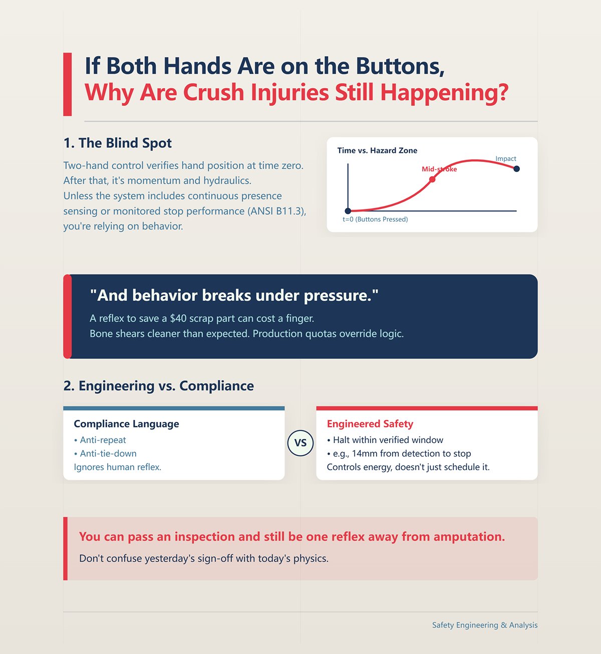
That’s the blind spot. Two‑hand control verifies hand position at time zero. After that, it’s momentum and hydraulics. Unless the system includes continuous presence sensing or a monitored stop performance that meets current ANSI B11.3 expectations, you’re relying on behavior.
And behavior breaks under pressure.
Twenty years ago I watched a man lose the end of his index finger because he tried to “just nudge” a slipping part during descent. Bone shears cleaner than you’d expect. He had two-hand controls. He also had a production quota.
Compliance language talks about anti‑repeat and anti‑tie‑down. It doesn’t talk about the human reflex to save a crooked bend worth forty bucks in scrap. The hazard zone is still open once the ram commits, and if your stopping performance isn’t engineered to halt within a verified window—think 14mm from detection to stop—you’re not controlling energy, you’re scheduling it.
You can pass an inspection and still be one reflex away from amputation. Don’t confuse yesterday’s sign‑off with today’s physics, or the fine that follows will have more zeros than your quarterly bonus.
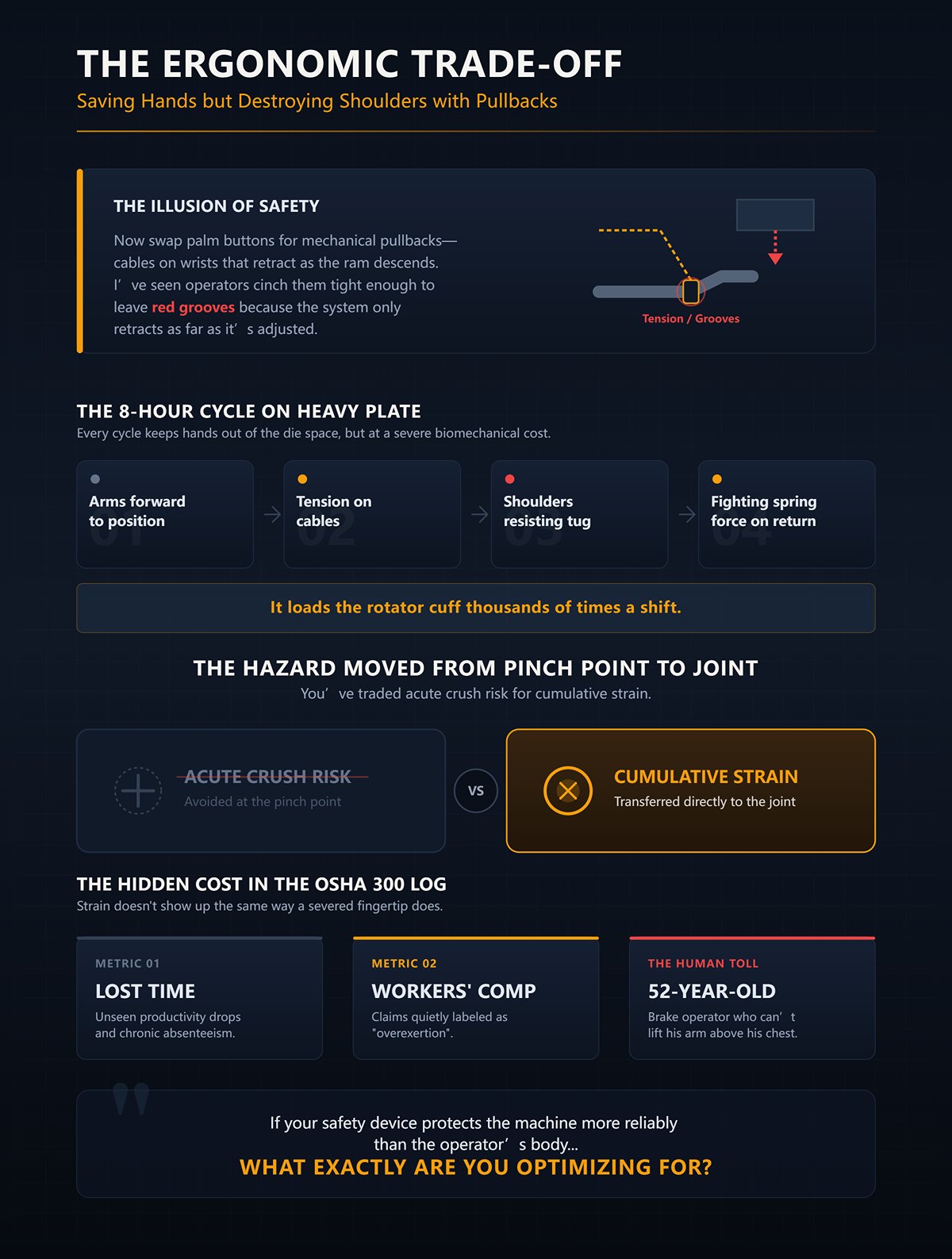
Now swap palm buttons for mechanical pullbacks—cables on wrists that retract as the ram descends. I’ve seen operators cinch them tight enough to leave red grooves because the system only retracts as far as it’s adjusted.
Run that for eight hours on heavy plate.
Every cycle: arms forward to position, tension on cables, shoulders resisting the tug as the ram drops, then fighting the spring force on return. It keeps hands out of the die space, sure. It also loads the rotator cuff thousands of times a shift.
You’ve traded acute crush risk for cumulative strain.
And strain doesn’t show up in the OSHA 300 log the same way a severed fingertip does. It shows up as lost time, workers’ comp claims labeled “overexertion,” and a 52‑year‑old brake operator who can’t lift his arm above his chest. The hazard moved from pinch point to joint.
If your safety device protects the machine more reliably than the operator’s body, what exactly are you optimizing for?
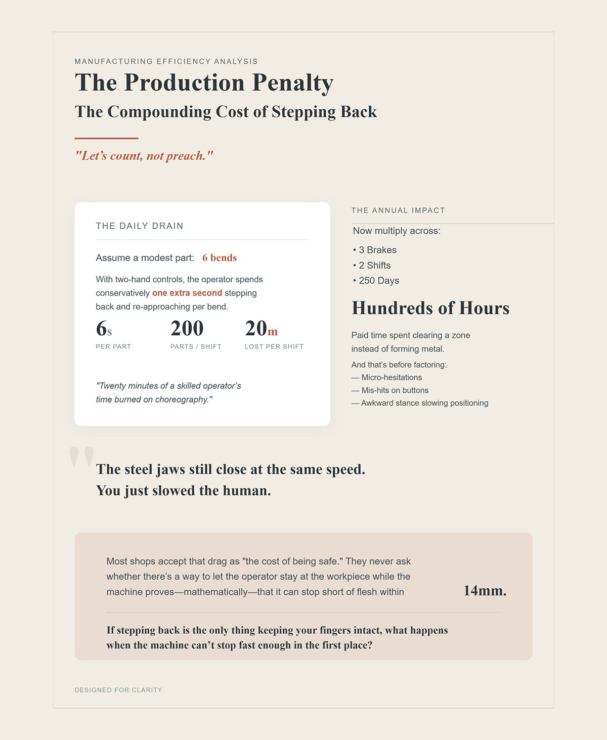
Let’s count, not preach.
Assume a modest part: 6 bends. With two‑hand controls, the operator spends—conservatively—one extra second stepping back and re‑approaching per bend. That’s 6 seconds per part. At 200 parts a shift, that’s 1,200 seconds. Twenty minutes.
Twenty minutes of a skilled operator’s time burned on choreography.
Now multiply across three brakes, two shifts, 250 days. You’re into hundreds of hours annually—paid time spent clearing a zone instead of forming metal. And that’s before you factor the micro‑hesitations, the mis‑hits on buttons, the awkward stance that slows positioning.
The steel jaws still close at the same speed. You just slowed the human.
Most shops accept that drag as “the cost of being safe.” They never ask whether there’s a way to let the operator stay at the workpiece while the machine proves—mathematically—that it can stop short of flesh within 14mm.
If stepping back is the only thing keeping your fingers intact, what happens when the machine can’t stop fast enough in the first place?
You’re standing at the brake, hands on a 36‑inch flange, eyes on the punch tip. The ram is coming down at production speed—well north of 10mm/s. Your instinct says: if something goes wrong, the safety system will stop it.
Here’s the question that actually matters: can it stop within 14mm of where your finger would be?
Not “does it have two buttons.” Not “is there a laser.” Not “did the salesman say it’s compliant.” Under ANSI B11.3, the entire risk model collapses into one brutal measurement—how far the ram travels from the moment a hazard is detected to the moment motion fully stops. If that distance exceeds 14mm at production speed, you do not have close‑proximity protection. You have theater.
And theater doesn’t slow steel.
The press brake is a closing set of jaws. Two‑hand controls step you back from the teeth before the bite. An AOPD—an active optoelectronic protective device—tries to time the bite so the jaws stop short. But neither matters if the machine’s stopping performance can’t physically meet that 14mm window.
So before you ask which safeguard is best, ask a harder one: what is your actual stopping distance, measured under load, today?
OSHA doesn’t care what you installed. They care about the relationship between stopping time and safety distance under 29 CFR 1910 Subpart O. That relationship is arithmetic, not opinion.
Here’s how it plays out on the floor.
If your brake runs faster than 10mm/s, ANSI B11.3 does not allow you to rely on “safe speed” alone. At those speeds, an operator can reach the die space before the ram can decelerate unless a presence‑sensing device detects intrusion and the ram stops within a verified distance—again, think 14mm as the critical threshold for close‑proximity AOPD systems.
Now picture a light curtain mounted 200mm from the pinch point. If your measured stopping distance is 120mm, you’re fine—on paper. But if an operator can stand between that curtain and the die, undetected, you’ve created a geometric blind spot. The standard explicitly requires additional protection in that scenario. Distance without detection is a loophole big enough for a hand.
So the real variable isn’t the device. It’s:
Stopping time × approach speed = minimum safe distance.
If you’ve never calculated that for your specific brake, with your hydraulic condition, at your production speed, you’re guessing. And guessing in front of an OSHA compliance officer turns into citations fast. They don’t fine brands of sensors. They fine unverified stopping performance.
| Topic | Details |
|---|---|
| Regulatory Basis | OSHA evaluates compliance based on the relationship between stopping time and safety distance under 29 CFR 1910 Subpart O. This relationship is arithmetic, not opinion. |
| Safe Speed Limitation | If brake speed exceeds 10 mm/s, ANSI B11.3 does not permit reliance on “safe speed” alone. |
| Risk at Higher Speeds | At speeds above 10 mm/s, an operator may reach the die space before the ram decelerates unless a presence-sensing device detects intrusion and stops the ram within a verified distance (e.g., 14 mm threshold for close-proximity AOPD systems). |
| Light Curtain Example | A light curtain mounted 200 mm from the pinch point with a measured stopping distance of 120 mm appears compliant on paper. |
| Geometric Blind Spot Risk | If an operator can stand undetected between the curtain and the die, a blind spot exists. Standards require additional protection in this case. Distance without detection creates serious risk. |
| Core Formula | Stopping time × approach speed = minimum safe distance |
| Compliance Risk | If stopping distance has not been calculated for the specific brake, hydraulic condition, and production speed, compliance is based on guesswork. OSHA cites unverified stopping performance—not sensor brands. |
Let’s get concrete.
An overrun test measures how far the ram travels after a stop signal is initiated. Not how fast it should stop. How fast it does stop. Under load. At temperature. On that machine.
You run the ram at normal approach speed. You trigger a stop—either through the control system or the AOPD test function. You measure the distance from signal to full stop. That number is your truth.
I’ve seen brakes advertised as “AOPD ready” that overran 22mm on a cold morning and 18mm after lunch when the oil thinned. Both numbers exceed 14mm. Both numbers disqualify the machine from true close‑proximity safeguarding under ANSI B11.3 expectations.
And here’s the kicker: OSHA guidance requires that stopping performance be monitored for deviation on each stroke. Not once a year. Not “when maintenance gets to it.” If your stopping time drifts and you don’t catch it, your calculated safe distance is fiction.
Fiction is expensive. Inspectors don’t argue about your intent; they measure your numbers.
So when a shop tells me, “We installed lasers, we’re covered,” my first question is simple: show me your last documented stopping distance test. If they can’t, the entire safety narrative falls apart in about thirty seconds.
If you can’t prove the ram stops short of flesh within 14mm, you don’t have engineered safety. You have optimism with wiring.
Now we get to the part nobody wants to hear.
AOPDs are brutally honest devices. Many systems built to ANSI B11.3 won’t let the brake cycle at full speed if the laser fails. Some won’t run at all. That’s not a design flaw—that’s the standard forcing a choice: fix the protection or stop production.
But here’s where shops get burned.
They bolt a modern AOPD onto a 20‑year‑old hydraulic system with worn proportional valves, sticky spools, and marginal pump response. The sensor detects intrusion in milliseconds. The control sends a stop command instantly. The valve hesitates. Pressure bleeds off slowly. The ram coasts.
Detection is fast. Deceleration is not.
If your hydraulic circuit cannot dump pressure and close flow quickly enough to meet that 14mm stopping window, the most sophisticated sensor in the world cannot save you. It becomes a witness to failure.
I’ve audited machines that were mechanically incapable of qualifying for close‑proximity AOPD because their stopping distance exceeded the allowable window. The standard is clear: brakes that cannot stop reliably within that distance are not functioning adequately to be fitted with that safeguarding method. You can’t software your way around sluggish oil.
So here’s the reality check.
Before you budget for lasers, before you promise operators they can stay at the workpiece without stepping back, you test the machine. You verify stopping distance. You evaluate valve response time, hydraulic pressure decay, and control latency as a system.
Because if your ram can’t stop within 14mm, every other safety device in the world is just theater—and the citation that follows won’t care how advanced your sensor looked in the brochure.
Let’s say your 1992 hydraulic brake overruns 18mm after lunch and 22mm on a cold start. You ran the test. You’ve got the numbers. So close to 14mm you can taste it — and still outside the window for true close‑proximity safeguarding under ANSI B11.3.
So what are your options?
If the machine cannot physically stop within 14mm, you have three honest paths. One: rebuild the hydraulic response — valves, seals, pressure decay, control latency — until the stop time qualifies. Two: move your presence‑sensing device farther from the die to match the real stopping distance, which increases the safety distance and pushes the operator back. Three: fall back to two‑hand control or perimeter guarding and accept the production hit.
That’s it. No fourth door.
But when the machine can meet the stopping requirement — verified, documented, monitored every stroke — that’s where the Active Opto‑Electronic Device earns its keep. Unlike two‑hand controls that force the operator to step back from the steel jaws, an AOPD rides the ram down, guarding the actual bite point until the mute point is reached. Protection lives where the hazard lives.
And that’s the pivot.
Two‑hand controls protect the start of motion. AOPD protects the dangerous motion.
If your safety device protects the machine more reliably than the operator’s body, what exactly are you optimizing for?
Picture a 10‑foot brake bending a shallow pan. A standard light curtain is mounted 200mm out from the die space to satisfy the calculated safety distance based on stopping time. Operator loads the blank, the ram starts down, and halfway through the stroke the return flange breaks the beam.
Stop. Reset. Cycle again.
That’s the nuisance trip everyone complains about.
The issue isn’t the curtain. It’s geometry.
Traditional light curtains create a vertical detection wall. Anything entering that wall stops the stroke. That’s perfect when your goal is to keep all personnel out of the entire danger zone during full strokes — especially on large parts or shared workspaces. But during box bending or flange work, the part itself becomes the intruder.
Close‑proximity laser AOPD systems work differently. They project a narrow sensing field just millimeters above the die opening and travel with the ram until the programmed mute point. Instead of guarding empty space 200mm away, they guard the pinch point directly — and they stop the ram if anything enters that zone before the mute depth.
No blind zone between curtain and die. No stepping back. No mid‑stroke beam breaks from the part geometry.
Modern systems even let you switch between modes — laser for tight box bends, light curtain for tall tooling or full‑height protection — through the HMI, with stop‑time monitoring active in both. That hybrid approach kills the old either‑or argument.
The nuisance trip wasn’t proof that light curtains are useless. It was proof that distance‑based guarding and point‑of‑operation work are solving different problems.
Mount a curtain far enough to satisfy your real stopping distance and you lose proximity. Mount it close without qualifying stopping time and you lose compliance.
And if your safety distance calculation doesn’t match your documented stopping performance, you’ve just handed an inspector a citation with your name on it.
Now we get into the part shops botch.
During a box bend, the flange must enter the detection field. If the system stopped every time metal crossed the beam, you’d never finish a part. So we use muting — a programmed point in the stroke where the AOPD allows material to enter because the remaining gap is less than the validated safe distance.
Done correctly, muting is tied directly to measured stopping distance. If your verified overrun is 13mm, the mute point is set so the ram cannot travel more than that remaining distance before full stop.
Done lazily, operators “blank out” zones or suppress the device for convenience.
Blanket suppression feels productive. Until someone reaches in during that unprotected window.
Under ANSI B11.3, muting must be controlled, documented, and tied to the stopping performance of that specific machine. Many modern AOPDs monitor stopping time on every stroke and will lock the machine out if deviation exceeds allowable limits. That’s not the system being difficult. That’s it preventing your mute calculation from becoming fiction.
I’ve seen shops disable stop‑time monitoring because nuisance lockouts slowed production. They were still “running lasers.”
He’s “compliant.”
Right up until the inspection report compares recorded stopping data to the required safety distance formula under 29 CFR 1910 Subpart O.
You cannot mute physics. And you cannot argue arithmetic with a compliance officer holding a tape measure and your own maintenance logs.
Let’s talk throughput.
On a two‑hand control setup, watch an experienced operator run 200 small brackets. Hands leave the part. Press buttons. Wait for descent. Hands return. Reposition.
That micro‑sequence takes maybe half a second longer per cycle than staying at the workpiece.
Half a second sounds trivial. Over 200 parts, that’s 100 seconds. Over 1,000 parts, that’s more than eight minutes. And that’s before you factor the micro‑hesitations, the mis‑hits on buttons, the awkward stance that slows positioning.
With close‑proximity AOPD, the operator’s hands never leave the part unless they choose to. The ram descends at normal speed, protection active until mute. No stepping back. No reaching for buttons. Just load, align, cycle, repeat.
Shops expect safety to cost time. When they switch from two‑hand control to properly configured AOPD on a brake that qualifies within 14mm, they’re often surprised to see equal or faster cycle times — because the operator’s motion got shorter.
Shorter motion. Less fatigue. Fewer micro‑delays.
But this only holds if the machine’s stopping performance is real and stable. If hydraulic lag forces you to mount protection farther away, you’re back to stepping out of the zone and killing that efficiency.
So here’s the hard boundary.
If your brake can’t reliably stop within 14mm, you either fix the hydraulics, accept increased safety distance with reduced proximity, or stay with two‑hand controls and slower output. AOPD is not magic. It is math riding on oil and steel.
And if you claim close‑proximity protection without documented stopping data to back it up, the production gain won’t matter when the fine lands on your desk.
Last fall I stood next to a 10‑foot press brake while an OSHA compliance officer flipped through a binder and asked three things: the latest stopping‑time test results, proof of risk assessment per ANSI B11.3, and records showing the stop‑time monitor hadn’t been bypassed. The shop had lasers on the ram. The owner kept saying, “We’re covered.”
The inspector didn’t care about the hardware. He cared about numbers.
He wanted documented overrun in millimeters at full operating temperature, confirmation that the system stopped within 14mm under worst‑case load, and evidence that muting points were calculated from that data—not guessed. He compared the recorded stopping distance to the configured mute depth. Then he asked for maintenance logs to prove the performance hadn’t drifted.
That’s what “inspection‑ready” looks like in practice: measured stopping distance (cold and warm), calculated safety distance, tied muting logic, automatic stop‑time monitoring enabled, and a risk assessment on file referencing ANSI B11.3 and B11.0 methodology. Not a sticker. Not a sales brochure. Arithmetic you can defend.
And if your paperwork says 14mm but your last verified stop was 18, that fine is coming with interest.
Now let’s talk about where the math meets the real world.
Picture a four‑sided box, 3‑inch flanges on all sides. On the third bend, those flanges stick up like antlers. As the ram descends, the part itself enters the sensing field. With a traditional light curtain mounted two feet out, you’re blanking zones left and right just to finish the part.
Blanking isn’t evil. Blind blanking is.
Under ANSI B11.3, close‑proximity AOPD is permitted only after a documented risk assessment. That assessment must consider part geometry, tooling height, operator reach, and the machine’s validated stopping performance. If the flange forces the operator’s hands within that 14mm stopping window before mute, you either adjust the process or switch modes.
Modern systems let you toggle from laser to curtain through the HMI, with stop‑time monitoring active in both. That hybrid setup handles maybe 95% of typical forming. The remaining 5%—tight boxes, tall tooling, awkward re‑strikes—demands discipline. Sometimes that means safe‑speed mode for part of the stroke. Sometimes it means re‑sequencing bends to keep hands clear during full speed.
What it never means is disabling the device because “the part keeps tripping it.”
I once saw a young operator reach around a partially muted zone to steady a box wall. The ram overran more than expected—hydraulic lag on a cold morning. He lost the tip of his index finger. Clean shear. No drama. Just steel jaws closing a few millimeters farther than the paperwork assumed.
You can argue with production schedules. You cannot argue with oil viscosity and gravity.
If your risk assessment doesn’t address complex geometry explicitly, an inspector will—and he’ll price that oversight accordingly.
Now grab a part that’s two inches wide. The operator’s fingertips are naturally within an inch of the die opening during alignment. At full approach speed, your only protection is the AOPD’s ability to detect intrusion and command a stop before the ram travels more than 14mm.
That assumes your hydraulics respond instantly and repeatably.
On older brakes, valve response time creates a measurable gap between stop signal and mechanical halt. I’ve recorded machines that met spec warm but exceeded it cold by several millimeters. That drift forces one of two choices: increase safety distance—killing proximity—or limit the ram to ≤10mm/s for the entire stroke.
Ten millimeters per second.
At that speed, you’ve erased the throughput advantage over two‑hand controls. Cycle times stretch. Operators get impatient. Management starts asking why the “faster” laser brake feels slow.
Because physics set the ceiling.
Safe‑speed modes exist for a reason. Use full speed for approach with active AOPD when validated. Transition to safe speed when hands must remain close and geometry won’t allow reliable mute separation. Program it. Document it. Train to it.
If your safety device protects the machine more reliably than the operator’s body, what exactly are you optimizing for?
Run small parts at full speed without verified stopping data, and you’re not just risking fingers—you’re gambling with a citation that will spell out your maximum ram speed in black ink.
Here’s where most shops lose both safety and production: they install AOPD and forget it.
Laser lenses collect oil mist. Mounting brackets get bumped during die changes. Wiring harnesses loosen. The system still powers up. The indicator stays green. But alignment drifts a millimeter at a time.
Modern AOPDs with integrated stop‑time monitoring will detect deviation and either force safe speed or lock the machine out. Operators hate that. Supervisors hate it more. So someone disables monitoring “temporarily.”
He’s “compliant.”
Until the day contamination causes intermittent detection faults and the machine reverts to ≤10mm/s every other stroke. Production tanks. Or worse, the system fails to detect a hand during a high‑speed approach because the beam geometry shifted outside calibrated tolerance.
Daily visual inspection. Weekly cleaning. Documented quarterly stopping‑time verification under full load. Annual risk assessment review. Those aren’t bureaucratic chores; they’re what keep the 14mm promise real instead of theoretical.
The fastest way to lose both protection and productivity is to assume the sensor will save you while ignoring the valve that can’t hit spec or the lens you haven’t wiped in six months.
Skip that discipline, and the next person calculating your stopping distance will be wearing a badge and writing numbers that start with a dollar sign.
You don’t stay inspection‑ready by buying a laser. You stay inspection‑ready by building a control system that can prove, on demand, that your ram will stop inside 14mm under real production conditions.
That’s the pivot most shops miss. They treat AOPD like a productivity upgrade and treat compliance like a binder on a shelf. Under ANSI B11.3, those two are the same thing. If your safeguarding isn’t control reliable, validated, and documented before the first production run, you’re not compliant—you’re just lucky. And luck runs out the day an inspector asks for your last stop‑time verification under full tonnage.
So the question isn’t “Do I have a laser?”
It’s “Can I defend every millimeter of ram travel between detection and stop?”
“Control reliable” means a single fault cannot result in loss of the safety function. Dual channels. Monitored feedback. Redundant valves. Fault detection that forces a safe state. That’s the language of ANSI B11.3 and the broader B11 family.
A standalone light curtain wired into an old clutch circuit isn’t that. Neither is a laser tied into a single solenoid valve with no monitoring of spool position. If the valve sticks and the ram coasts past 14mm, your sensor did its job. Your hydraulics didn’t. And the standard doesn’t grade on effort.
Integration means the AOPD signal feeds a safety-rated control system that monitors stop time continuously or at defined intervals. It means your hydraulic valves are designed or retrofitted for redundancy and self-checking. It means a fault forces safe speed or lockout—not “cycle anyway.”
That’s where most retrofits collapse. Shops add a premium sensor to a control architecture built in 1992 and call it modern. He’s “compliant.”
Until an inspector traces the safety circuit, sees no monitoring of valve response, and asks how you guarantee the stop distance that justifies close‑proximity operation. That’s when the conversation turns into a citation with commas in it.
If your safety device protects the machine more reliably than the operator’s body, what exactly are you optimizing for?
You don’t start with a quote. You start with a hazard assessment.
Before a purchase order ever leaves your desk, you document: machine model, tonnage, measured stopping time warm and cold, tooling heights, typical part geometries, operator reach envelopes, and which jobs fall inside that 14mm eligibility window. If the machine cannot consistently stop within that window, the standard is blunt: it is not functioning adequately enough to be fitted with close‑proximity AOPD.
That’s not a preference. That’s disqualification.
Now here’s the non‑obvious part: this assessment protects production as much as safety. When you map which jobs require hybrid modes—laser plus curtain, or laser plus safe speed—you prevent the Friday‑afternoon panic where someone disables a channel because “the part keeps tripping it.” You’ve already defined which 5% of jobs need alternate safeguarding and programmed them accordingly.
Inspectors don’t expect perfection. They expect evidence. A written risk assessment referencing ANSI B11.3 clauses, documented stop‑time tests under load, and defined safeguarding modes per job family tells them you’re managing risk, not reacting to it.
Walk them through that math calmly.
Or let them do it for you with a calculator and a penalty schedule.
Two‑hand controls trained a generation to step back from the jaws and hold buttons until a quarter inch from bottom. That’s not just a method; it’s muscle memory. When you move to foot‑switch operation with close‑proximity AOPD, you’re asking operators to hold parts near moving steel and trust the timing of the stop.
Trust doesn’t come from a manual. It comes from demonstration.
You show them the measured stop distance. You explain what 14mm means in physical space—less than the thickness of their little finger. You demonstrate fault conditions: block the beam, watch the machine force safe speed. Simulate a valve fault and show the lockout. Now the system isn’t magic; it’s predictable.
And that’s before you factor the micro‑hesitations, the mis‑hits on buttons, the awkward stance that slows positioning. When operators realize they can stabilize small parts naturally, trigger with a foot pedal, and maintain full approach speed because the stop time has been validated, throughput stops fighting safety.
But you also train the boundaries. Which jobs require safe speed. Which require switching to curtain mode. Which require reverting to two‑hand control because geometry defeats proximity sensing. AOPD outperforms two‑hand controls where both are viable; it does not erase them from your toolkit.
Make that clear, or an operator will improvise.
And improvisation is what inspectors call “willful.”
Here’s the lens I want you to carry forward: compliance isn’t a device choice. It’s a chain of defensible physics, wired into control reliability, documented before production, and reinforced until it rewires muscle memory.
When you build the system that way, the steel jaws don’t get slower. They get predictable. And predictability is what lets you run at full speed without gambling on fingers or fines.
Now look at your oldest brake and ask yourself one hard question: can it truly stop inside 14mm—cold, loaded, and verified—or are you designing a safety strategy around a machine that was never eligible in the first place?


