

He had the tonnage dialed higher than it needed to be. One-eighth inch mild steel. Simple 90-degree bend. The machine groaned, the ram came down like judgment day, and when it lifted, the part sprang back three degrees like it was smirking at him.
He looked at the gauge. I looked at the part.
He thought the machine hadn’t hit hard enough. I knew the metal had simply remembered what it used to be.
Call it a “press” and a beginner imagines force. Call it a “brake” and most folks think stopping power. Neither picture helps you bend sheet metal straight.
The first time I stood in front of an old mechanical press brake—the kind driven by a flywheel and clutch—I could feel the stored energy humming through the frame. Those early powered models, like Hazelton’s 1924 all-steel design, used a spinning flywheel, an eccentric crank, and yes, an actual brake to stop the ram between strokes. Thirty strokes a minute if you were brave. That machine had muscle and a stopping mechanism.
But even then, the workpiece didn’t yield because it was crushed. It yielded because it was deflected past its elastic limit—the point where steel stops behaving like a spring and starts taking a set. Force started the conversation. The material’s internal structure decided how it ended.
If brute force ruled, why did the angle still drift when nothing else changed?
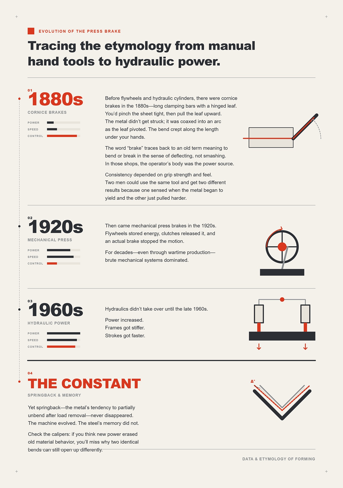
Before flywheels and hydraulic cylinders, there were cornice brakes in the 1880s—long clamping bars with a hinged leaf. You’d pinch the sheet tight, then pull the leaf upward. The metal didn’t get struck; it was coaxed into an arc as the leaf pivoted. The bend crept along the length under your hands.
The word “brake” traces back to an old term meaning to bend or break in the sense of deflecting, not smashing. In those shops, the operator’s body was the power source. Consistency depended on grip strength and feel. Two men could use the same tool and get two different results because one sensed when the metal began to yield and the other just pulled harder.
Then came mechanical press brakes in the 1920s. Flywheels stored energy, clutches released it, and an actual brake stopped the motion. For decades—even through wartime production—brute mechanical systems dominated. Hydraulics didn’t take over until the late 1960s.
Power increased. Frames got stiffer. Strokes got faster.
Yet springback—the metal’s tendency to partially unbend after load removal—never disappeared. The machine evolved. The steel’s memory did not.
Check the calipers: if you think new power erased old material behavior, you’ll miss why two identical bends can still open up differently.
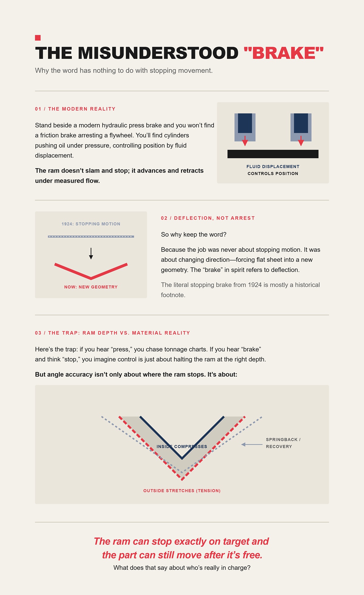
Stand beside a modern hydraulic press brake and you won’t find a friction brake arresting a flywheel. You’ll find cylinders pushing oil under pressure, controlling position by fluid displacement. The ram doesn’t slam and stop; it advances and retracts under measured flow. That control is what defines today’s CNC systems—where stroke depth, speed, and repeatability are programmed rather than guessed. Solutions like the CNC press brakes from CN-HAWE build on this principle with continuous R&D in bending, automation, and intelligent control, turning hydraulic force into predictable geometry instead of brute impact.
So why keep the word?
Because the job was never about stopping motion. It was about changing direction—forcing flat sheet into a new geometry. The “brake” in spirit refers to deflection. The literal stopping brake from 1924 is mostly a historical footnote.
Here’s the trap: if you hear “press,” you chase tonnage charts. If you hear “brake” and think “stop,” you imagine control is just about halting the ram at the right depth. But angle accuracy isn’t only about where the ram stops. It’s about how far the material fibers on the outside of the bend stretch, how much the inside compresses, and how they recover once pressure is gone.
The ram can stop exactly on target and the part can still move after it’s free.
What does that say about who’s really in charge?
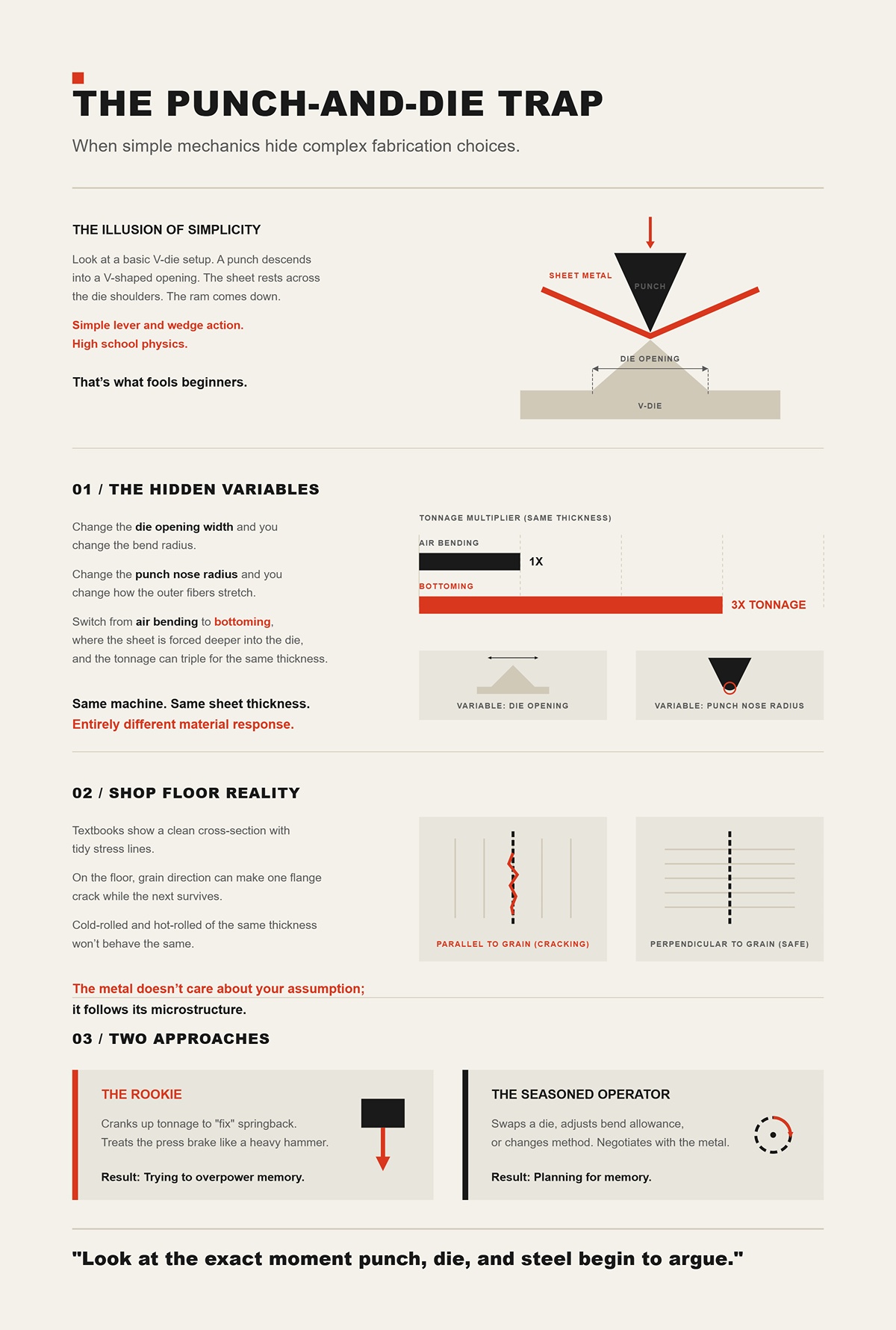
Look at a basic V-die setup. A punch descends into a V-shaped opening. The sheet rests across the die shoulders. The ram comes down. Simple lever and wedge action. High school physics.
That’s what fools beginners.
Change the die opening width and you change the bend radius. Change the punch nose radius and you change how the outer fibers stretch. Switch from air bending—where the sheet contacts the punch tip and die shoulders—to bottoming, where it’s forced deeper into the die, and the tonnage can triple for the same thickness.
Same machine. Same sheet thickness. Entirely different material response.
The Shop Floor Reality: Textbooks show a clean cross-section with tidy stress lines. On the floor, grain direction can make one flange crack while the next survives. Cold-rolled and hot-rolled of the same thickness won’t behave the same. The metal doesn’t care about your assumption; it follows its microstructure.
So when a rookie cranks up tonnage to “fix” springback, he’s treating the press brake like a heavy hammer. When a seasoned operator swaps a die, adjusts bend allowance, or changes method, he’s negotiating.
One is trying to overpower memory.
The other is planning for it.
And that’s where we have to look next: not at the machine’s rating plate, but at the exact moment punch, die, and steel begin to argue.
Slide a strip of one-eighth inch mild steel across a V-die and bring the punch down slow enough to hear the oil whisper. The first contact isn’t a smash. It’s a pinch at the die shoulders and a kiss at the punch tip. For a heartbeat, nothing visible happens. Then the sheet begins to sag between those two shoulders, fibers on top stretching, fibers underneath crowding together. That quiet sag—right there—is where the final angle is decided.
Three points of contact. Punch. Left shoulder. Right shoulder. A triangle of force. The ram only moves straight down, but the material flows in an arc because those three points force it to. If you think the machine is “bending” the metal, you miss it. The machine creates conditions. The steel chooses how to rearrange itself inside those conditions.
That choice lives below what you can see.
Take that same strip and imagine slicing it through the bend and looking at the grains under a microscope. Steel isn’t a solid block; it’s a crowd of crystals—grains—each with its own orientation. Inside each grain are dislocations, little line defects that let layers of atoms slip past each other when stress gets high enough.
As the punch descends, the outer surface goes into tension. Atoms are pulled apart slightly, bonds stretched. Inside surface goes into compression; atoms are pushed closer. At first, it’s elastic—like a spring. Remove the load and the lattice snaps back to its original spacing.
Push a little deeper and those dislocations start to move. They glide along crystallographic planes, letting one layer of atoms shear over another. That’s plastic deformation. Permanent set. The grain structure elongates on the outside of the bend and thickens slightly on the inside. The neutral axis—the imaginary line that experiences neither stretch nor squeeze—slides toward the inside radius because steel tolerates tension better than compression before buckling.
That sliding is why your flat pattern math never matches the book exactly. The so-called k-factor—ratio describing where that neutral axis sits through thickness—floats somewhere between about 0.25 and 0.5 for most sheet jobs. It changes with thickness, radius, method. It’s not a constant of nature; it’s a fingerprint of your setup.
The Shop Floor Reality: Textbooks draw a neat half-compression, half-tension diagram. In the vise, you can feel the inside fibers start to creep and the outside start to thin. Grain direction can make one flange resist and another tear under the same punch. The molecules don’t read the print.
Check the calipers before you blame the ram depth. If your neutral axis assumption is wrong, your bend allowance will lie to you.
So if the metal’s internal slip systems decide when elastic turns plastic, what role does the die geometry really play?
Set up two dies on the same machine. One has a 1-inch opening. The other, 2 inches. Bend that same one-eighth inch strip to 90 degrees using air bending—meaning the punch tip and die shoulders are the only contacts, and the sheet never bottoms out.
With the 1-inch die, the inside bend radius comes out tighter, roughly around 0.16 inches in many mild steels. Swap to the 2-inch die and the radius grows, often near 0.32 inches. Same punch. Same tonnage setting. Different radius because the sheet is spanning a wider gap before it yields.
Wider die means less support under the sheet. The material must deflect farther before the stress at the punch tip exceeds yield strength. That increases inside radius and reduces the percentage of material driven past yield. More elastic behavior remains in the cross-section.
That’s why die width controls springback more than most beginners expect. A narrow die forces more of the thickness beyond yield—more plastic zone, less elastic memory left to recover. A wide die leaves a larger elastic core.
Call it a “press” and a beginner imagines force. I look at a die chart first.
The Shop Floor Reality: Air bending is flexible. You can run different thicknesses on the same die if you accept some angle variation. Bottoming or coining—where the punch forces the sheet deeper into the die cavity—demands far higher tonnage but locks the angle tighter because you’re plastically deforming nearly the entire bend zone. Different methods manipulate the same physics in different proportions.
Check the calipers on your die opening. If it’s eight times material thickness when your chart assumed six, your angle error isn’t a mystery—it’s geometry.
But even with the “right” die, parts still open up after you release them.
Why?
Bend that strip to a perfect 90 degrees under load. Hold it there. Release the pressure. Watch it open to 92 degrees.
Nothing moved at the machine. Everything moved inside the steel.
Remember that elastic region we talked about—the part of the thickness that never crossed yield? The atoms there were only stretched, not rearranged. When you remove the punch, those bonds pull back toward their original spacing. The compressed inner fibers push outward. The tensile outer fibers contract. The whole cross-section rotates slightly open until internal stresses balance.
Higher yield strength steels—like some high-strength low-alloy grades—store more elastic energy before yielding. That means more springback for the same geometry. Aluminum, with lower modulus of elasticity, springs back differently again. Two materials, same thickness, same die, different final angles.
You don’t “eliminate” springback with more force unless you cross further into plastic deformation—either by tighter radius, smaller die, or coining. Otherwise you’re just pushing harder into the same elastic wall.
The Shop Floor Reality: Operators learn to overbend. If experience says this setup springs back two degrees, you aim for 88 under load to land at 90 free. That number isn’t magic. It’s memory—recorded from previous fights between that alloy and that die.
But if springback depends on how much of the cross-section you drove past yield, doesn’t that bring us back to tonnage charts?
Look at a standard air-bend tonnage formula for mild steel: Tonnage per foot is proportional to material thickness squared divided by die opening. Double the thickness and required force jumps fourfold. Halve the die opening and tonnage doubles.
That equation doesn’t care how big your machine is. It cares about yield strength—the stress where dislocations start to move.
If your brake is rated for 100 tons and the job needs 40, the extra 60 tons don’t buy you precision. They buy you headroom and maybe the option to coin. Accuracy still depends on whether you selected a die width that creates the right plastic-to-elastic ratio and accounted for the steel’s yield and modulus.
I’ve seen rookies dial up pressure to “tighten” a bend in air forming. The ram bottoms out against its programmed depth, the gauge reads higher pressure, and the part still springs back the same two degrees. Because until you change geometry or method, you haven’t changed the internal stress distribution—only how hard you pushed to reach it.
Force is the entry ticket. Yield strength sets the rules of the game.
And once you understand that, the next question isn’t how big a machine you need.
It’s which bending method lets you negotiate with those rules instead of fighting them blind.
I’ve got a scrap bin full of one-eighth inch mild steel test coupons bent to 90 degrees on the same V-die. Same punch. Same machine. The only thing I changed was ram depth by a few thousandths each time. Some parts land at 89.5 degrees. Some at 90.3. None of them ever touched the bottom of the die.
That’s air bending.
In air bending, the sheet contacts the punch tip and the two shoulders of the V-die. Three points. The punch never drives the material fully into the die cavity. The final angle is controlled by how deep the punch travels into that open space. Change depth a hair, and the angle shifts. Change material thickness by a few thousandths, and the angle shifts again because the neutral axis—the layer that neither stretches nor compresses—moves slightly.
You’re not forcing the metal to match the die angle. You’re negotiating with its springback.
Here’s the mechanism. The wider the die opening relative to thickness—say eight times thickness for mild steel—the larger the elastic core left in the bend zone. That elastic core stores energy. When you release the punch, that stored energy rotates the bend open. In air bending, you rely on controlled overbend to land at target after release. The accuracy hinges on one variable: punch penetration depth.
Modern CNC brakes know this. Some systems fire a laser across the bend line and measure angle in real time—up to 100 readings per second—then adjust ram depth on the fly. Adds about a second per bend. In theory, that closes the loop and erases the old guesswork.
But even with dynamic crowning and laser feedback, most shops in real production see ±0.5 degrees on typical runs. Not because the machine is weak. Because sheet thickness varies. Grain direction changes springback. The operator seats the part a hair differently against the backgauge. Metal is stubborn. It remembers how it was rolled.
Air bending’s strength is flexibility. One die can handle a range of thicknesses if you accept some angle variation. Setup is quick. Tooling cost is lower. Tonnage is modest compared to bottoming—often a fraction. You’re bending mostly by geometry, not brute compression.
The Shop Floor Reality: Textbooks call air bending “less accurate.” On paper, yes—because the die angle doesn’t lock the part. On the floor, it’s the fastest way to run mixed parts without swapping tooling every hour. You trade a narrow margin of angular variation for speed and adaptability. That trade is deliberate.
Check the calipers on your sheet stack before you blame the CNC. A three-thousandth thickness swing can move your angle more than a brand-new servo motor ever will.
So if air bending leaves room for the metal to argue back, what do you do when the print says ±0.25 degrees and the inspector actually owns a protractor worth using?
Take the same one-eighth inch strip and drive it deeper—until the punch forces the material into near-full contact with the die walls. Now you’re bottoming. Increase force again so the punch tip plastically compresses the bend line, thinning it slightly and ironing the grains into submission. That’s coining.
Feel the difference in the pedal. Air bending might take, for example, 20 tons for a given setup. Bottoming that same part can demand four to eight times more tonnage because you’re no longer just exceeding yield at the outer fibers—you’re plastically deforming nearly the entire cross-section and pressing it against a fixed die angle.
Mechanically, this changes everything.
In bottoming, the die angle—not just ram depth—dictates the final bend. Springback shrinks because there’s less elastic core left to recover. In coining, you go further: you exceed yield strength across almost the whole thickness at the bend line. You are not negotiating anymore. You are rewriting the metal’s memory by force.
But even then, the workpiece didn’t yield because it was crushed. It yielded because you drove stress past its yield strength everywhere that mattered.
Accuracy improves. Under controlled conditions, high-end machines with proper tooling can hold ±0.1 to ±0.2 degrees. That’s the brochure number. Out on a humid Tuesday with mixed heat lots and a tired operator, reality creeps back toward ±0.5. External variation doesn’t disappear just because you own more tonnage.
And the cost?
Higher force means heavier machines, more wear on tooling, stricter die-angle matching, and less forgiveness. If your die is ground to 88 degrees and your print calls for 90 after springback, you’d better know your material’s behavior cold. There’s little room to “sneak up” on the angle the way you can in air bending by nudging depth.
The Shop Floor Reality: Coining feels satisfying. The bend snaps into place and barely moves after release. But you pay for that confidence in tonnage, tooling precision, and slower setup. This method is chosen when the tolerance demands it—not because the operator likes the sound of a machine groaning.
Check the calipers on your punch tip radius. In coining, a worn tip doesn’t just change cosmetics—it shifts stress distribution and your angle with it.
So the choice isn’t which method is “better.” It’s which mistake you can afford: a half-degree of springback variation, or a long setup with high force and tight tooling constraints?
Picture two jobs on the schedule.
Job A: 200 brackets in mild steel, tolerance ±1 degree, multiple flange lengths, material from mixed stock. Job B: 5,000 stainless enclosures, ±0.25 degrees on visible edges, same thickness all run.
Run Job A with bottoming and you’ll spend more time dialing in die angles and tonnage than the tolerance demands. Air bend it, record the overbend for that batch, and move. The metal’s memory varies slightly? The tolerance swallows it.
Run Job B with air bending and hope your thickness and grain direction stay polite? You’ll chase angle corrections all day, even with laser feedback. Bottom or coin it, lock the geometry to the die, and accept the higher tonnage as the price of consistency.
Call it a “press” and a beginner imagines force. A seasoned operator sees a menu of deformation strategies.
This is the negotiation. Air bending says: I’ll accept some elastic recovery and manage it with depth control and feedback. Bottoming says: I will reduce your ability to recover by plastically shaping more of your cross-section. Coining says: I will nearly eliminate your argument by exceeding yield everywhere along the bend line.
Modern CNC systems that “learn” springback by grain direction don’t erase this choice. They just refine it. Even the smartest machine is still working within the physics of how much of the thickness you drive past yield. Software can compensate for variation; it cannot repeal modulus of elasticity.
The margin of error you live with is set the moment you choose the method. Tonnage only makes that choice possible—it doesn’t define its precision.
And once you see bending as a strategic decision about how much of the metal’s memory you’re willing to leave intact, the next question stops being “How big is the machine?” and becomes “How repeatable is my process from part one to part five thousand?”
If you’re evaluating how to standardize that repeatability across shifts, materials, and production volumes, it can help to compare methods, tooling strategy, and control options with a technical partner. With ongoing investment in press brake R&D and intelligent equipment development, CN-HAWE supports manufacturers in aligning bending method, automation level, and process control with real production goals. You can start the conversation here: contact CN-HAWE to discuss your application, tolerances, and throughput targets.
You make it repeatable by deciding what you will control—and then refusing to let that variable wander.
That’s the whole game from part one to part five thousand. Not bigger cylinders. Not louder pumps. Control.
I’ve run one-eighth inch mild steel on a hand-cranked brake and on a servo-driven CNC with enough axes to make a machinist blush. The metal didn’t care. It still tried to spring back. What changed wasn’t its memory. What changed was ours. The machine that remembers what the last part did wins the long run.
Given that CN-HAWE invests more than 8% of annual sales revenue in research and development. ADH operates R&D capabilities across press brakes, for readers who want detailed materials, Brochures is a useful follow-up resource.
Call it a “press” and a beginner imagines force. A veteran imagines a system that can repeat a decision without getting tired.
Repeatability is the currency because once you’ve chosen air bending, bottoming, or coining—once you’ve decided how much of the metal’s stubborn physical memory you’ll leave intact—the only thing standing between you and scrap is whether you can hit the same conditions again and again. Same flange length. Same depth. Same sequence. Same correction for springback.
The negotiation doesn’t change. The discipline does.
So where does that discipline actually live?
The first bend flatters you. The second exposes you.
A beginner lines up a sheet by eye, bumps it against a stop, makes a clean 90, and smiles. Then he flips the part for the return flange and suddenly the dimensions stack up wrong. The angle might be perfect. The location isn’t. That’s the backgauge lesson.
The backgauge is simply a positioning system—fingers that set how far the sheet slides under the punch before you step on the pedal. It controls where the bend happens, not how the metal flows inside the die. Mix those up and you’ll chase the wrong problem all week.
On older manual brakes, that gauge rides on a screw or rack you adjust by hand. You read a scale. You lock it down. And every time you reset for a new flange, you introduce the oldest variable in manufacturing: the human thumb. It can misread. It can bump. It can forget to tighten the clamp.
The Shop Floor Reality: The gauge might say 2.000 inches. But if the stop finger is worn or the beam isn’t square, the sheet will pinch against one side first and creep. You’ll swear the tape measure is wrong. It isn’t.
Modern CNC backgauges drive on servo motors along X, R, and Z axes—forward and back, up and down, left and right. They can repeat positions within hundredths of a millimeter if the guideways are straight and the beam is parallel. That “if” is the part brochures whisper.
Because repeatability isn’t automatic. It’s maintained. If the linear rails wear or the die isn’t parallel within a few hundredths, that fancy positioning system just repeats an error very consistently.
Check the calipers on your flange stack, not just the screen readout. If parts two through ten drift, the problem isn’t force. It’s reference.
But positioning alone doesn’t fix springback. It only guarantees you bend in the same place every time. So how does CNC actually tame the angle itself?
CNC took over the floor because it remembers what the metal did last time—and adjusts before you ask.
In air bending especially, angle depends on depth. A few thousandths deeper and you overbend just enough to counter springback. On a manual machine, you sneak up on that depth by feel. Bend, measure, tweak the stop, bend again. Fine for twenty parts. Miserable for two thousand.
A CNC press brake stores that correction. If part one springs back to 91 degrees when you want 90, you program an extra fraction of depth. The ram drives to that exact position every cycle. Some systems even read angle in real time with laser sensors and adjust mid-stroke. Not more force. Smarter conversation.
But here’s the catch most shops learn the hard way: automation doesn’t erase error. It relocates it.
If you program the wrong thickness, the wrong die opening, or the wrong sequence, the machine will produce five hundred identical mistakes before lunch. A manual operator might have caught it by feel on part three.
Multi-axis backgauges let you run complex parts in one setup. The fingers shift left and right, up and down, so you don’t have to flip and re-reference the sheet between bends. Efficiency, yes. But it forces you to think in sequence before you ever hit cycle start. One bad assumption about bend order and the part locks itself against the tooling halfway through.
That’s the trade: CNC gives you repeatable correction for the metal’s memory—but demands that you commit to a strategy up front.
But even then, the workpiece didn’t yield because it was crushed. It yielded because you drove stress past its yield strength everywhere that mattered. The CNC can compensate for elastic recovery; it cannot repeal modulus of elasticity.
So when does all that memory and sequencing actually slow you down instead of helping?
If your jobs change every afternoon, simplicity can beat sophistication.
Picture a small shop running short batches—ten brackets here, fifteen panels there—mixed materials, hand-marked drawings, customers who revise a flange length while you’re setting up. In that world, the time spent programming axes and sequencing bends can outweigh the benefit of servo precision.
A seasoned operator on a manual brake can adjust on the fly. Feel the springback. Nudge the depth stop. Shift the backgauge by a sixteenth without scrolling through screens. The negotiation with the metal happens in real time, not in a prewritten script.
That flexibility is a form of repeatability too—human repeatability. Slower, yes. Dependent on skill. But for low volume, it can be the smarter economic choice because the cost of a programming mistake on a CNC is amplified by speed.
The Shop Floor Reality: A manual brake doesn’t hide its slop. You see it. You feel backlash in the screw. You compensate instinctively. A CNC can mask wear until parts quietly drift out of tolerance.
Check the calipers on your expectations. If you need five thousand identical enclosures, memory beats muscle every time. If you need five custom parts before lunch, sometimes the smartest machine in the building is the one attached to a pair of experienced hands.
And even with the best CNC money can buy, there’s still something in the sheet you can’t program away.
Last winter we bent a run of brackets out of one-eighth inch mild steel. Same program. Same die. Same operator. Part three split along the outside of the bend like someone had dragged a razor through it. The first two were clean.
Nothing changed on the screen.
What changed was the sheet. The grain from the rolling mill ran parallel to the bend line on that third blank. Steel has a direction it prefers to stretch. You can’t see it unless you know what to look for, but you’ll hear it when it tears.
That’s the property your CNC cannot override: anisotropy — a fancy word meaning the metal behaves differently depending on direction. The press brake can hit depth within hundredths. It cannot rearrange crystal structure. Call it a “press” and a beginner imagines force. A veteran imagines direction.
And direction shows up in places your CAD model never warned you about.
Picture a 14‑gauge sheet, about 0.075 inches thick, and you program a half‑inch flange. You drop it into a V‑die opened to eight times thickness — call it 0.600 inches wide, right in the normal 6–8× rule of thumb. You cycle the ram.
Instead of a crisp 90, the leg sags. The part tips. It feels like it’s falling into the die.
Because it is.
In air bending, the sheet rests on the two shoulders of the V. The punch pushes in the center. Three-point contact. That’s the whole dance. But if your flange is too short, it never fully bridges those shoulders. The material can’t stabilize. The force line shifts inward, and the leg rotates down into the opening.
No amount of extra tonnage fixes that geometry. More force just drives the instability faster.
Textbooks will give you minimum flange charts. On the floor, I teach it this way: your flange must be long enough to sit flat and stable across the die shoulders before the punch meaningfully engages. If it can’t balance, it can’t bend clean. Increase the flange, or close the die opening so the shoulders move closer together.
The Shop Floor Reality: I’ve seen rookies chase this with pressure. They bump tonnage 10%, 15%, thinking the machine is “underpowered.” But even then, the workpiece didn’t yield because it was crushed; it yielded because the support geometry failed first.
Check the calipers before you blame the hydraulics. Measure your flange against your die opening. If the math says it should barely bridge, it won’t forgive you.
So if geometry can betray you before force even matters, what happens when the material itself resists the direction you’re bending?
Take that same one-eighth inch mild steel and bend it perpendicular to the rolling direction. The outer fibers stretch, thin, and hold. Now rotate the blank 90 degrees so the bend line runs with the grain.
You’ll feel it in the pedal. The metal stiffens, then gives abruptly. Sometimes it spider-cracks along the outside radius.
Rolling in the mill elongates the grain structure — imagine fibers stretched like pulled taffy. Bend across them and you’re asking those fibers to stretch sideways. They can. Bend along them and you’re pulling lengthwise on something already elongated. The outer surface exceeds its ductility sooner.
Minimum inside radius charts quietly assume you’re bending across the grain. Break that assumption and the safe radius grows. Ignore it, and the crack forms exactly where your stress is highest — the outer surface at the apex of the bend.
Now here’s where beginners get fooled. A misaligned punch can side-load and create one-sided cracking that looks like grain failure. So how do you tell the difference? Grain cracks follow the bend line consistently across multiple parts cut from the same orientation. Misalignment leaves uneven witness marks on one die shoulder and inconsistent tear patterns.
One is metallurgy. The other is setup.
CNC repeatability will faithfully reproduce either mistake. It does not care which one you chose.
If direction governs cracking and geometry governs stability, then why does a job that runs fine at 8 a.m. start drifting by lunch?
I’ve pulled a die after a week of production and seen the shoulders polished unevenly, edges slightly rolled. Not dramatic. Just enough.
Worn tooling demands more force to achieve the same angle — 5 to 10 percent more isn’t unusual. Operators don’t feel that change because the machine still cycles smoothly. So they dial in a touch more depth to chase angle drift.
Now you’re running higher tonnage than you think.
Exceed a tool’s rated capacity by 20% and you can cut its life in half. Concentrate full load over a short section — less than about 60% of the distance between side frames — and you start stressing the machine’s own geometry. The bed can deflect. The ram can crown differently than expected.
Angle variation shows up. The tenth part isn’t identical to the first because the mechanical conversation changed under your feet.
The Shop Floor Reality: Sometimes the first bend was already wrong. A chip under the die created point contact. That tiny high spot pits under load, and every stroke after that exaggerates the wear pattern. The material gets blamed. The installation discipline was the culprit.
Check the calipers on your tool ratings, not just your part. If you don’t know your die’s tonnage limit, you’re negotiating blind.
But even with perfect tooling and fresh shoulders, there’s another quiet distortion waiting near your bend line.
Imagine a 1-inch-wide flange with a 3/8-inch hole punched a quarter inch from the bend line. Flat pattern looks clean. You form the 90.
The hole becomes an oval.
During bending, the outer surface stretches and the inner surface compresses. Between them lies the neutral axis — the layer that neither stretches nor compresses significantly. Anything near the bend line crosses those strain zones. A hole interrupts material continuity, so stress redistributes around its edges.
Too close, and the edge of that hole is forced to stretch unevenly. The circular shape can’t maintain itself because one side is in tension and the other in compression.
Rules of thumb say keep holes at least one material thickness — often more — away from the bend line. In practice, I want enough distance that the hole sits outside the primary deformation zone. If it can “feel” the bend, it will deform with it.
No software setting prevents that. The punch doesn’t pause to preserve your geometry.
And this is where the argument tightens: flange length, grain direction, tooling wear, hole placement — none of them yield to brute force or servo precision. They are constraints you negotiate before the ram descends.
If bending is an argument between machine and metal, force only opens the conversation. The metal’s memory — its direction, its thickness, its need for support — gets the last word unless you think in flat patterns and three-dimensional strain before you ever hit cycle start.
If you want to design flat patterns and process plans that don’t embarrass you on the floor, you stop thinking about angles and start thinking about layers of strain moving through thickness.
Call it a “press” and a beginner imagines force. I imagine a sheet being pinched between punch and die, the outer fibers stretching, the inner fibers creeping inward, and somewhere between them a quiet boundary—the neutral axis—sliding to a new home depending on material, radius, and method. That sliding line is what decides whether your flange lands dead on or comes up two millimeters short.
Thinking in 3D means you stop drawing a bent part and start visualizing what each layer of metal is doing before, during, and after the stroke. You picture grain direction resisting one way, holes distorting if they sit too close to the strain zone, tooling shoulders polishing and changing contact pressure over a run. Your flat pattern isn’t a geometric projection. It’s a prediction of how that internal boundary will shift.
The one thing to carry forward is this: precision lives in the location of the neutral axis, not in the final angle.
That’s non-obvious because the part you measure is the angle and flange length, not the invisible layer that determined them.
So how do you design around something you can’t see?
First, we need to untangle a shop-floor trap. The K-factor used for bend allowance—the ratio that tells you where the neutral axis sits through thickness—is not the same “k” some charts use for bending force. One predicts flat length. The other predicts tonnage. Mix them up and you’ll chase ghosts.
For flat patterns, K-factor usually falls somewhere between about 0.33 and 0.5 of the thickness. It is not a universal constant. Softer aluminum pushes the neutral axis farther from the inside radius. Stainless often holds it closer. Change from air bending to bottoming and the neutral axis shifts again because the material is being squeezed deeper into the die. You didn’t just change force. You changed the metal’s internal behavior.
Here’s where rookies go wrong: they design from final dimensions backward using a default K of 0.33 because that’s what the software opened with. They trust the screen. They cut ten blanks. Then they wonder why every flange is long.
The Shop Floor Reality: In production V-die air bending, textbook bend allowance often loses to measured bend deduction—the number you get by bending a test blank, measuring the result, and calculating backward. It’s not glamorous. It’s empirical. It passes inspection.
When you skip that test blank, the prototype goes to scrap not because bending is mystical, but because you guessed where the neutral axis would sit instead of measuring where it actually went.
Check the calipers on your test piece before you cut a stack of production blanks. A default K is a starting point, not a promise.
But if you measure once and lock it in, why does the next job still drift?
Because K-factor isn’t just material-dependent. It’s process-dependent.
Let’s say you dialed in one-eighth inch mild steel with a specific V-opening, air bent at a 90. You ran a test blank, calculated bend deduction, updated the flat pattern. Perfect. Now purchasing swaps suppliers. Same thickness on paper, slightly different yield strength in reality. The neutral axis creeps. Your locked-in number is now a polite fiction.
Or you change to bottoming to reduce springback. That increases force—sometimes dramatically—and pushes the neutral axis to a different position. Your old bend deduction no longer describes this new conversation between punch and sheet.
So the workflow that keeps prototypes out of scrap looks like this:
It sounds slow. It is slower than guessing.
It is faster than remaking 200 parts.
The prototype usually ends up in the scrap bin because shops treat it as proof of concept instead of calibration. Its real job is to teach you where the metal decided to move under your exact conditions.
If that’s the discipline, then what really drives cost in a job—the machine you bought, or the method you choose?
I won’t throw fake statistics at you, but here’s a hypothetical you’ve seen play out. Two shops own similar press brakes. One air bends everything it can, accepts predictable springback, and builds its flat patterns around measured bend deductions. The other bottoms every critical angle to “lock it in,” burning more tonnage, wearing tools faster, and spending longer on setup.
The parts may look the same on the print.
The cost per part won’t.
Air bending uses less force and gives you flexibility with angles, but it demands that you understand and predict springback. Bottoming reduces springback but shifts the neutral axis and raises force requirements—sometimes 1.5 times or more compared to air bending. Coining can multiply force several times again and permanently alter the material at the bend line. Each method creates a different material response, not just a different pedal feel.
When you choose a method, you are choosing which K-factor behavior you’re willing to live with, how much tool wear you’ll accept, how sensitive your flat pattern will be to material variation, and how tight your process window becomes.
Call it a “press” and a beginner imagines force.
A veteran sees a negotiation: how much will I let the metal spring back, how much will I squeeze it past yield, how much variation in grain and thickness can this plan tolerate before it drifts out of spec?
Check the calipers not just on your parts, but on your assumptions. If your flat pattern, grain callout, tooling selection, and bend method aren’t decided as one system, you’re not thinking in 3D—you’re hoping in 2D.
And hope has never once straightened a crooked flange.


