

I watched a senior operator crack a $400 punch because he re-ran bend allowance math at the control after the first part came out 1.5 degrees open. He tweaked the Y-depth by feel, hit cycle, and the material bottomed harder than the previous sheet. Scrap part. Damaged tooling. Ten minutes of silence.
He wasn’t careless. He was alone.
That’s what “programming at the pedal” really looks like when the scrap bin hits 15%.
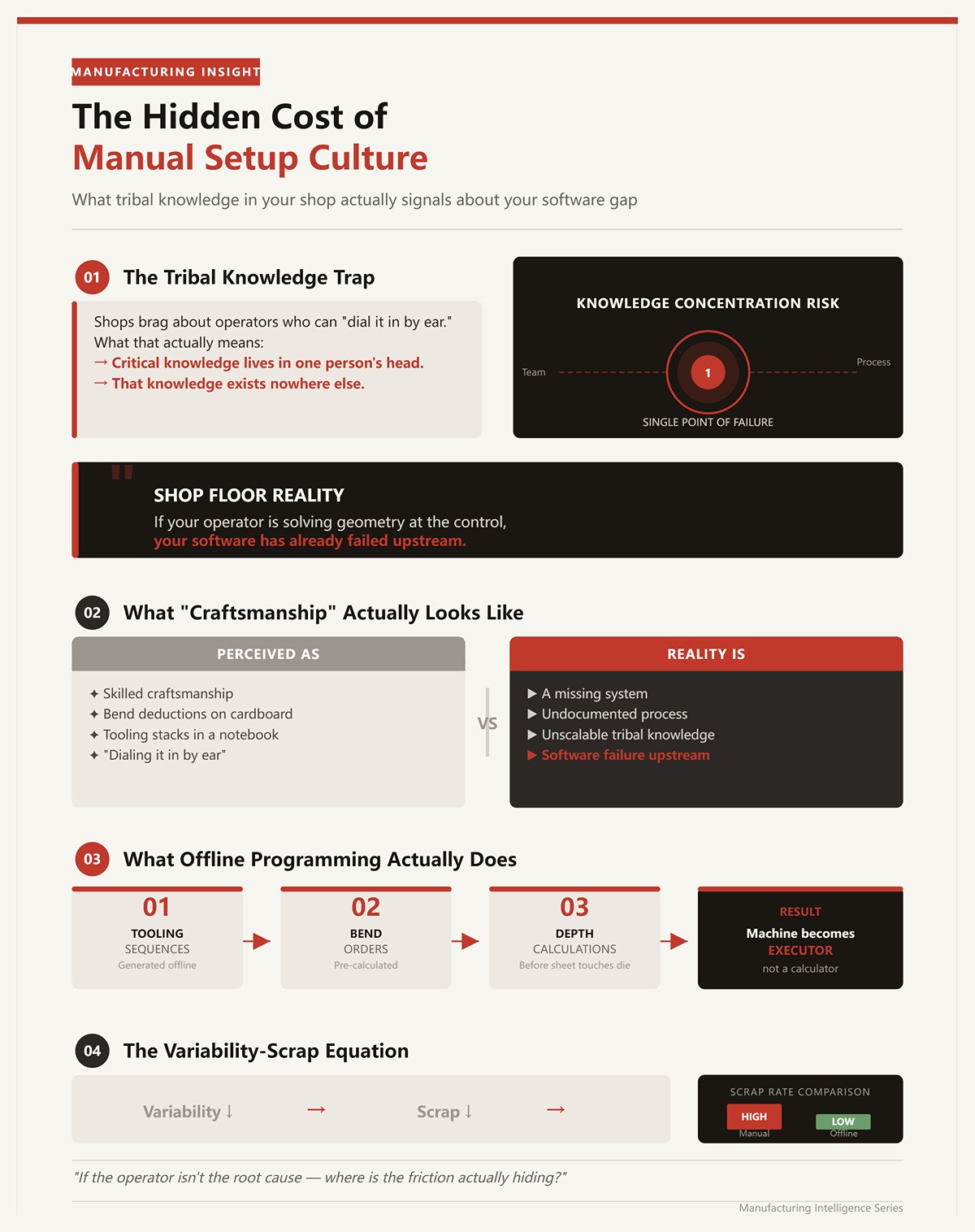
I’ve seen shops brag about operators who can “dial it in by ear.” What that usually means is the tribal knowledge lives in one person’s head and nowhere else.
When your best brake operator writes bend deductions on cardboard and keeps tooling stacks in a notebook, that isn’t craftsmanship—it’s a missing system.
Shop Floor Reality: If your operator is solving geometry at the control, your software has already failed upstream.
Offline programming isn’t about pretty 3D parts. It’s about removing human memory from the critical path. When tooling sequences, bend orders, and depth calculations are generated before the sheet ever touches the die, the machine becomes an executor, not a calculator. Scrap drops because variability drops.
So if the operator isn’t the root cause, where is the friction actually hiding?
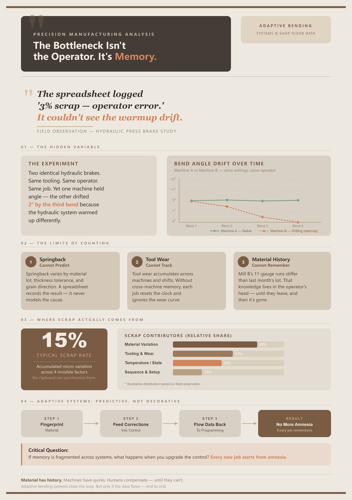
I once ran two identical hydraulic brakes on the same job, same tooling, same operator. One held angle. The other drifted two degrees by the third bend because the hydraulic system warmed up differently.
The spreadsheet didn’t catch that. It only logged “3% scrap — operator error.”
Spreadsheets are fine for counting damage. They cannot predict springback, track tool wear across machines, or remember that this batch of 11-gauge from Mill B runs stiffer than last month’s lot.
Material has history. Machines have quirks. Humans compensate until they can’t.
Shop Floor Reality: A 15% scrap rate is usually accumulated micro-variation—material, tooling, temperature, sequence—none of which a clipboard can synchronize.
Modern adaptive bending systems reduce scrap because they fingerprint material and feed corrections back into the control. That’s predictive, not decorative. But unless that data flows back into your programming environment, every new job starts from amnesia.
If memory is fragmented, what happens when you upgrade the control?
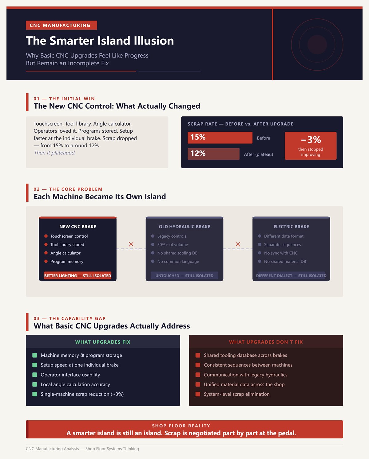
I remember the first time we replaced a tired backgauge with a new CNC control. Touchscreen. Tool library. Angle calculator built in. The operators loved it.
Scrap dropped—from 15% to maybe 12%.
Then it plateaued.
The control stored programs, yes. But it didn’t standardize tooling across brakes. It didn’t enforce consistent sequences. It didn’t talk to the older hydraulic in the corner that still ran half our volume. Each machine became its own island with better lighting.
That’s the illusion: faster setup at one brake feels like system improvement.
Shop Floor Reality: A smarter island is still an island.
Basic CNC upgrades improve the machine’s memory. They do nothing for shared language between machines, tooling databases, and programming logic. Until your hydraulics and electrics speak the same tooling and material data, your scrap rate is negotiated part by part at the pedal.
And if the real disease is isolation between machines, what exactly are those glossy 3D simulations actually curing?
I watched a salesman spin a flawless 3D part on a 70-inch monitor while my lead operator stood there with a cracked gooseneck punch in his hand. The model showed every bend in glossy blue. No collisions. No warnings. Just perfect, pretend metal folding in slow motion.
We ran the same part that afternoon on our older hydraulic. Third bend, the ram descended, and the return flange clipped the backgauge finger because the actual punch in the rack had a slightly longer tang than the library model. The software knew “gooseneck.” It didn’t know the one we cracked last Tuesday and replaced with a different brand.
The animation wasn’t lying. It was incomplete.
That’s the split nobody wants to admit. There’s simulation that calculates, and there’s simulation that decorates. The spinning 3D model? That’s presentation. The underlying collision engine—if it’s built on real tool profiles and real machine envelopes—is something else entirely. When shops conflate the two, they think buying prettier graphics fixes isolation between tooling, programming, and machines. It doesn’t.
If smarter controls created smarter islands, flashy 3D often creates prettier ones.
I once programmed a deep four-sided box with two internal hems. Looked easy in flat. First attempt in real life? The final return flange had nowhere to go; the punch body interfered with the already-formed wall. We learned that at 90 tons, mid-cycle.
A proper collision engine would have caught it before a sheet was even cut.
Not the cartoon version. The real one. The kind that extrudes the exact punch profile—radius, shoulder width, tang length—and sweeps it through each bend step against the actual machine geometry. Advanced systems use bounding volume hierarchies (BVH) to check collisions efficiently, meaning they don’t just unfold and refold; they simulate each incremental motion of the tool in space.
In controlled testing environments, researchers have shown that a small but critical percentage of complex parts—around 5% in one large dataset of hundreds of realistic geometries—had no viable final bend because of unavoidable tool collisions. Flat pattern looked fine. Basic unfolding said “manufacturable.” Only full 3D tool-aware collision detection exposed the dead end.
That feature pays for itself the first time you avoid laser-cutting 200 blanks that physically cannot be formed.
Shop Floor Reality: Collision detection tied to real tooling data prevents crashes; spinning a shaded model does not.
But here’s the catch: collision avoidance only works if your tooling database matches your rack. If the software thinks your punch shoulder is 0.590 and the one in the machine measures 0.630, your “digital twin” is just pretend metal with better lighting. So the question becomes less “Does it look realistic?” and more “Is it fed with the same tooling language every brake understands?”
And collision is only half the war. What about the bend angle itself?
I had a batch of 11-gauge that consistently came off 1.5 degrees open. Same program. Same tooling. Same operator. Different heat lot.
Static geometry doesn’t know that.
A flat CAD model assumes ideal plastic deformation—bend to 90, get 90. Real steel has yield strength, tensile strength, grain direction, and thickness variation. Springback is the material elastically recovering after load removal, and it shifts your final angle based on those properties.
Serious offline software doesn’t just draw the bend; it calculates overbend based on material models. Feed it yield strength from a mill cert, thickness from actual measurement, inside radius tied to your die opening, and it estimates how far past 90 you must go to land at 90 after release.
Some shops pair that with real-time angle measurement—lasers or mechanical sensors that pause near bottom dead center and correct the final stroke. Powerful. But those sensors need cleaning, calibration, and stable reference points. In a dirty shop, they drift. When they drift, they amplify error instead of correcting it.
Which means the most robust system is one where measured corrections feed back into the offline database. If this heat lot of 11-gauge runs 1.5 degrees open, the next program for that material shouldn’t start from scratch.
But unless that data flows back into your programming environment, every new job starts from amnesia.
Pretty 3D graphics don’t manage that loop. Material-aware algorithms tied to shared databases do. And that only matters if every brake—hydraulic dinosaur and shiny servo-electric—reads from the same playbook.
So what breaks when the inputs aren’t disciplined?
| Section | Content |
|---|---|
| Real-World Problem | A batch of 11-gauge consistently came off 1.5 degrees open despite using the same program, tooling, and operator—only the heat lot was different. |
| Limitation of Static Geometry | A flat CAD model assumes ideal plastic deformation—bend to 90°, get 90°. It does not account for variations in yield strength, tensile strength, grain direction, or thickness. |
| What Causes Springback | Springback occurs when material elastically recovers after load removal, shifting the final bend angle based on material properties. |
| Role of Offline Software | Advanced software calculates required overbend using material models rather than just drawing bends. |
| Required Inputs for Accuracy | Yield strength (from mill certificate), actual thickness measurements, and inside radius tied to die opening are used to estimate necessary overbend. |
| Real-Time Angle Measurement | Some shops use lasers or mechanical sensors to measure angles near bottom dead center and automatically correct the final stroke. |
| Risks of Sensor Systems | Sensors require cleaning, calibration, and stable reference points. In dirty environments, drift can occur, amplifying errors instead of correcting them. |
| Most Robust Approach | Measured corrections should feed back into the offline database so future programs account for known material behavior (e.g., 1.5° open for a specific heat lot). |
| Data Flow Problem | Without feedback into the programming environment, each new job starts without historical correction data. |
| Graphics vs. Intelligence | 3D graphics alone do not manage correction loops; material-aware algorithms connected to shared databases do. |
| System-Wide Consistency | All press brakes—hydraulic or servo-electric—must reference the same shared data system for consistency. |
| Closing Question | What fails when material and process inputs are not properly controlled? |
We once trusted a beautiful simulation on a large panel with five sequential bends. The software cleared every step. No red flags. Setup looked bulletproof.
First part ran clean. Second part? Angle drifted because the hydraulic oil warmed up. By the fourth part, cumulative error meant the last flange missed its target by two degrees, and the simulated clearance vanished in the real world. What was “safe” in the model became a light rub in steel.
The model assumed static machine behavior. The machine was alive.
Simulation engines are deterministic. They assume the machine frame deflects within defined parameters, the backgauge repeats within tolerance, the tooling seats perfectly, the material matches the database. Break any one of those assumptions—worn die shoulders, swapped punch brands, uncalibrated crowning—and the virtual world drifts from the physical one.
That’s when 3D becomes a false confidence machine. The operator trusts the green checkmark and stops questioning setup. Scrap doesn’t come from ignorance; it comes from misplaced certainty.
Shop Floor Reality: If your operator is solving geometry at the control, your software has already failed upstream—but if your simulation ignores real tooling, material feedback, and machine variability, it fails just as quietly.
The irony is that high-end simulation absolutely has a place. Machine builders use it to validate entirely new bending concepts before steel is ever cut. That’s innovation work—designing the machine itself. On the shop floor, we’re not inventing physics. We’re trying to repeat it, consistently, across mismatched brakes that barely speak to each other.
So the real question isn’t whether 3D simulation works.
It’s whether your simulation is connected tightly enough to tooling automation and shared machine data to stop being pretend metal—and start acting like a translator every brake in the building can understand.
Third shift. Two operators. A rush job with eight bends. The programmer had already “finished” it in the control—bend order optimized, collisions cleared, angles calculated. Looked clean on the screen.
Forty-five minutes later the machine still hadn’t cycled a good part.
Why? Because the program knew the bend sequence. It didn’t know the machine.
The operator was hunting through the rack for a 30-degree punch that matched the virtual one, splitting a 10-foot die into staged segments because the control hadn’t planned for tooling length, then rewriting backgauge positions after realizing the physical fingers would crash into a previously formed flange. The simulation was right about geometry. It was silent about setup reality.
That’s the gap this section lives in.
A bend sequence answers one question: in what order do I deform this flat pattern so it doesn’t collide with itself?
Programming a machine answers a different one: with which exact punch and die segments, staged in what physical order along the bed, with what clamping zones, crowning values, and gauge clearances, so an operator can load tools once and run parts without thinking?
Those are not the same task.
I’ve watched software spit out a “perfect” eight-step sequence that required five full tool changes because it optimized for collision, not for common tooling across bends. On paper, efficient. On the floor, dead time.
Dedicated offline systems worth paying for treat tooling as a constrained resource. They evaluate bend order and tool selection together, searching for sequences that minimize changeovers, reuse die openings, and respect the actual segmented lengths in your library. That’s combinatorial logic, not just graphics.
When that logic works, setup time drops hard. Many shops report roughly 50% reduction in setup after moving programming offline—not because the bends changed, but because the tooling plan was decided before the operator touched a wrench. The brake keeps cycling while programming happens elsewhere.
Miss that distinction, and you end up babysitting a million-dollar brake with a crescent wrench in hand.
I once had a hydraulic brake from the early 2000s sitting next to a new servo-electric. Two different controllers. Two different OEM software ecosystems. Both claimed “automatic tooling.”
Each one only truly understood its own dialect.
OEM-tied systems are like proprietary quick-clamps: slick inside their own world, awkward everywhere else. Their tooling libraries default to that manufacturer’s punches, radii, safety zones. Try to build a shared database across brands and you’re exporting, reformatting, or—worse—retyping.
A neutral CAD/CAM platform that supports multiple brands flips the structure. One master tooling library. One material database. Post-processors translate that shared intent into each controller’s native language.
Think of it as a shop-wide translator. The geometry and tooling strategy live in one place; the output adapts per machine.
Without that neutrality, every brake becomes an island with its own memory. Change a punch shoulder dimension in one system and the others keep believing the old number. That’s how “pretend metal” creeps back in.
The risk, of course, is compatibility theater—software claiming multi-brand support but only deeply integrating with a few. If your legacy hydraulic can’t accept uploaded programs or lacks communication ports, no amount of neutrality fixes that. Which means software selection has to start with a hardware audit, not a demo reel.
And that raises the uncomfortable question: how automatic is “automatic,” really?
I’ve tested auto-tooling modules that proudly generated a full tool stack in seconds. Impressive—until we ran a non-standard part with mixed flange heights and a limited die rack.
The first pass required three manual overrides: swapping to a narrower punch to clear a return flange, forcing a shared die opening to reduce changeovers, and restaging segments because the software assumed full-length tools we didn’t own.
Auto-tooling reduces intervention. It does not eliminate it.
In practical terms, straightforward parts—simple boxes, consistent material, complete tooling library—can run hands-off from CAD to machine file. Complex geometries or incomplete libraries expose the cracks. The better systems fail gracefully: they flag constraint conflicts, show why a tool was chosen, and let you override with traceable logic that feeds back into the database.
Weak systems just dump a sequence and leave the operator to solve geometry at the control.
Shop Floor Reality: If your operator is solving geometry at the control, your software has already failed upstream.
The real metric isn’t “Does it auto-generate?” It’s “After generation, how many decisions are still made with a wrench instead of a mouse?”
If the answer is “a few, and they get stored back into the shared library,” you’re building a common language. If the answer is “depends on the machine,” you’re back to dialects.
And dialects are manageable—until your fleet spans three generations of hydraulics and electrics that don’t naturally speak to each other at all.
I’ve got a 1998 hydraulic brake that leaks just enough oil to perfume the shop and a brand-new servo-electric that throws a timing fault if you look at it wrong. Same part. Same tooling on paper. Two completely different personalities when you hit cycle start.
On the hydraulic, ram synchronization is handled by oil flow through proportional valves. It drifts slowly; you compensate with crowning and pressure tweaks. On the servo, synchronization is encoder-driven—ball screws, servo motors, position loops. It’s precise until a loose coupling or thermal overload throws the axes out of sync and the control demands a ritual: power cycle, jog, quarter-turn on a trim knob, watch for the right indicator blink.
So when you ask, “What level of automation is realistic in a mixed shop?” here’s the honest answer: you can automate geometry and tooling strategy across machines. You cannot automate away the physics and control architecture differences between hydraulic pressure control and servo position control.
That’s the crack software has to bridge.
Until your 1998 hydraulic and your brand-new servo share the same tooling brain, you don’t have a system—you have islands.
I watched a servo-electric throw uneven bend angles across a 6-foot flange because one ball screw lagged a few thousandths. The simulation had shown perfect parallelism. The post assumed hydraulic-style pressure equalization—both sides “naturally” sharing load through oil.
Servos don’t “naturally” share anything. They obey position commands. If one side’s feedback loop is off, it will happily bend out of square with surgical precision.
Hydraulics, especially heavy-tonnage units, still dominate thick plate because they deliver consistent force across the stroke. Electric servos shine in repeatability and energy efficiency on lighter gauges. Hybrids mix both, sometimes keeping mechanical clutches or flywheels for peak power because pure servos struggle with acceleration smoothness at high tonnage.
Different machines solve force and motion in different ways.
But most offline software abstracts them into the same bend model: target angle, material factor, backgauge position, ram depth.
That abstraction is useful—until it hides the control assumptions.
If your post-processor sends identical depth-based commands to a hydraulic that thinks in pressure and a servo that thinks in position, you’re trusting two different feedback philosophies to land on the same angle. Sometimes they will. Sometimes you’ll be 5 degrees open and arguing about who touched the crowning.
Shop Floor Reality: Automation fails at the seam where software assumes physics is universal.
So what does your software actually know about the machine it’s posting to—control type, compensation method, sync behavior—or is it just spitting numbers and hoping the controller figures it out?
I once changed a punch shoulder radius in our main library after we chipped it on a rush job. Updated it in the offline system. Forgot the OEM control on the older brake had its own local copy.
Next week, same part ran on the legacy hydraulic. Operator trusted the control’s library. Collision.
Not because the geometry was wrong. Because two databases disagreed about a 0.5 mm detail.
When you mix brands and generations, you’re really mixing data ownership models. Older hydraulics often store tooling locally in the controller with limited import capability. Newer electrics expect networked libraries, sometimes cloud-synced. OEM ecosystems prefer their own catalogs. Third-party systems promise neutrality.
The question isn’t “Can I build a master tooling library?”
It’s “Which system is the authority—and which ones are just consuming translations?”
If the servo’s control auto-adjusts for tool height offsets but the hydraulic relies on manual shim entries, your centralized database must store not just geometry but machine-specific offset logic. Otherwise the same punch becomes two different physical realities depending on where it’s mounted.
That’s why neutral CAD/CAM matters—but neutrality without enforcement is theater. If operators can edit tooling at the control without pushing changes back upstream, you’re back to memory fragmentation.
But unless that data flows back into your programming environment, every new job starts from amnesia.
And amnesia is expensive.
So even if you solve data ownership on paper, how much of the machine’s behavior can you actually see and standardize—especially on older iron?
We bolted linear scales onto an old hydraulic to improve repeatability. Added angle measurement at the ram. Tied it into the offline system so actual bend results could inform springback factors.
It helped. Scrap dropped on repeat jobs because we weren’t guessing material correction every time.
But here’s what we couldn’t see: internal valve response lag, oil temperature variability across shifts, micro-wear in mechanical linkages. The servo next to it reports motor torque, axis load, positional error in real time. The hydraulic gives you pressure and depth—and a lot of educated guessing.
Even retrofitted, the older machine has “dark zones” in its behavior.
And some of that darkness is structural. Early servo upgrades in heavy presses kept mechanical clutches for peak force because motors alone couldn’t handle the dynamics smoothly. That mechanical engagement often isn’t instrumented at the same fidelity as modern servo loops. You can measure output position. You can’t always see the transient mechanical compliance inside.
So what’s realistically automatable?
You can standardize tooling libraries. You can unify bend sequences and staging logic. You can push consistent programs across machines. You can collect angle feedback where sensors exist.
You cannot fully equalize machine personalities without redesigning them.
Shop Floor Reality: Forcing legacy hydraulics to “talk” doesn’t mean making them think like servos—it means building software smart enough to translate between pressure-driven muscle and encoder-driven precision.
And once you’ve got them speaking the same tooling language, the next question isn’t about compatibility anymore.
It’s about visibility.
Do you optimize bends first and then monitor performance—or do you need real-time feedback before any optimization means a damn thing?
I once watched a $180,000 electric brake sit idle for 27 minutes because a clamp wasn’t where the program said it would be. The screen showed green lights. The dashboard later reported “minor stoppage.” The job still shipped late.
So do you need real-time feedback across every machine before automation can actually work?
No.
But if you can’t see what your machines are doing minute by minute, you’re guessing at where your bottleneck really lives.
This is the pivot. Offline programming forces legacy hydraulics and modern electrics to speak the same tooling language. Monitoring tells you whether they’re actually having the conversation — or just nodding politely while bleeding time in setup, adjustment, and micro-stoppages. One is the translator. The other is the court reporter. Without the transcript, you don’t know who lied.
And without that visibility, ROI is a bedtime story.
I bolted angle sensors onto an older hydraulic thinking I’d finally killed springback guesswork. Two weeks later the readings drifted because nobody cleaned the lenses, and the “self-correcting” system started chasing dirt instead of steel.
Real-time doesn’t mean reliable.
There’s a difference between preventing the next bad bend and documenting the last one. High-frequency PLC feeds can categorize downtime by alarm code, cycle interruption, axis fault — beautiful granularity. But if your team needs three months to understand the dashboard, you just installed another machine that requires babysitting.
Shop Floor Reality: A monitoring layer that demands its own maintenance becomes another source of downtime.
Post-run reports tell you what happened. Real-time feeds can tell you while it’s happening — but they still lag by a few milliseconds, sometimes a few seconds, and they don’t rewrite a bad bend sequence already posted to the control. Monitoring doesn’t fix geometry. It exposes friction.
Which begs the question: what are you actually trying to fix first — scrap, or time?
I once swore our average setup was “about 20 minutes.” We finally tracked it properly — clock started at first tool out of the rack, stopped at first good part — and the real number was 38.
That’s the number that matters.
If offline software automates tooling sequences, pre-stages clamps, and eliminates control-side edits, you should see setup drop. Not in theory. In minutes. But if you don’t know your baseline by machine, shift, and operator, you can’t prove improvement — you can only feel busier.
Hypothetical example: say offline programming cuts setup by 12 minutes per job on a brake running 10 jobs a day. That’s two hours recovered. Multiply by labor rate and machine burden. Now you have a number. Without tracking, you have a vibe.
Shop Floor Reality: If you can’t see setup time by the minute, you’re guessing at ROI and calling it strategy.
Monitoring isn’t the cure. It’s the scale.
And you don’t diet without a scale.
I’ve seen shops with a wall-mounted dashboard screaming OEE percentages while programmers tweak bend deductions in total isolation. Two systems. Two realities.
That’s how you get what I call split-brain manufacturing.
Your programming layer generates tooling sequences, bend orders, and depth targets. Your monitoring layer records downtime, alarms, cycle counts. If they don’t talk, you can’t correlate a spike in micro-stops to a specific tooling configuration or bend strategy. You just see “downtime increased.”
But unless that data flows back into your programming environment, every new job starts from amnesia.
Modern electrics with built-in predictive features blur this line. They can self-adjust angle, compensate for drift, flag maintenance before failure. Impressive. But those optimizations live inside that one control. Your 1998 hydraulic across the aisle doesn’t benefit. Your offline system doesn’t learn unless you force the data upstream.
So you end up with smarter islands again.
The real move isn’t choosing between monitoring and offline automation. It’s sequencing them correctly: use monitoring to establish baseline truth, deploy offline tooling automation to attack setup and inconsistency, then feed performance back to refine programs across the fleet.
Visibility first. Translation second. Enforcement third.
If you skip the order, you’re optimizing in the dark — and that’s how I almost bankrupted my floor once already.
So where do you actually start building a controlled bending system without drowning in software before it pays you back?
I once signed a purchase order for a “fully integrated bending solution” after one glossy demo. Six months later, we had three new logins, two dashboards nobody trusted, and the same 5 degrees open on a 90 that should have been dead square.
The mistake wasn’t buying software.
It was buying in the wrong order.
You don’t build a controlled bending system by stacking features. You build it by attacking your dominant loss first — scrap, downtime, or blindness — and forcing every machine to speak the same tooling language before you ask them to sing in harmony. Monitoring is the scale. Automation is the diet. But you still have to decide what you’re overweight on.
So where do you begin without drowning?
A few years back we scrapped a batch of 3/16 brackets because the flange hit the backgauge finger on bend three. Program looked fine on screen. Operator swore he followed it. The collision happened anyway.
That wasn’t an operator problem.
It wasn’t even a machine problem.
It was a classification problem.
Programming error means the bend sequence, tooling layout, or depth targets were wrong before the first tool came out of the rack. Execution error means the program was right, but something drifted — worn punch radius, dirty die seat, operator override. Visibility error means neither programming nor execution was obviously wrong, but nobody saw the setup time creep from 20 to 38 minutes or the micro-stops stacking up between bends.
If you can’t name which bucket your last failure falls into, you’re not ready to buy anything.
Shop Floor Reality: If your operator is solving geometry at the control, your software has already failed upstream.
Answer that one question honestly and the fog starts to lift. But what if the honest answer hurts?
I cracked a $400 gooseneck because our program called for a tool we didn’t actually have in that station. The control didn’t care. It just did what it was told.
That’s a programming loss.
If scrap and rework are eating you alive, your first dollar doesn’t go to prettier simulation. It goes to offline CAM that enforces real tooling libraries, real clamp zones, real machine limits — not pretend metal.
Offline programming is a translator. It takes tribal knowledge from your best brake guy and forces it into a repeatable tooling sequence that works on the 1998 hydraulic and the new servo-electric. Same bend order. Same tool callouts. Same depth logic.
When done right, setup shrinks because the program already decided which punches, in what order, in which stations. The operator loads and runs. He’s not improvising.
Now the uncomfortable counterpoint.
There are shops that swap in a new CNC brake and see ROI in under a year without touching software. I’ve seen it. Hardware alone can stabilize angle control and cut drift. But if that new machine becomes another smarter island — with its own tooling database and its own way of thinking — you’ve reduced variability on one brake and preserved chaos across the fleet.
If rework is systemic, software that standardizes tooling logic across machines will outlast any single piece of iron.
But what if scrap isn’t your real bleed?
We had a hydraulic that “felt unreliable.” That was the official diagnosis. Felt.
Once we wired basic machine-state monitoring across the floor, we learned it wasn’t breaking down. It was sitting idle waiting for material 14% of the shift and waiting for programs 9%.
That’s a visibility loss dressed up as mechanical failure.
If your pain is unplanned downtime — not scrap, but machines sitting quiet when they should be cycling — you start with universal monitoring. Not a boutique dashboard on the newest brake. All of them. Same definitions. Same timestamps. Same language for “running,” “setup,” “alarm,” “idle.”
Because until you see downtime categorized by cause, you’ll keep blaming hydraulics for scheduling mistakes.
Shop Floor Reality: A machine that’s 85% mechanically available but 60% actually utilized doesn’t need a retrofit first. It needs truth.
Monitoring here isn’t the cure. It’s the flashlight. And unless that data flows back into your programming environment, every new job starts from amnesia.
So you’ve classified your dominant loss. You’ve picked your first layer. Now what keeps you from drifting back into feature shopping?
I’ve sat through demos where the sales guy zoomed a 3D model, spun it, section-cut it, and called it “full digital twin capability.” On the floor, we called it pretend metal.
Features are isolated promises.
A controlled bending system is a conversation.
You’re not buying “offline CAM” or “monitoring.” You’re designing a stack where:
That’s a language system.
Legacy hydraulics don’t have to become electric. Old controls don’t have to become new. But they do have to speak the same bending dialect, or you’re managing translators forever.
Here’s the non-obvious part.
The right starting point isn’t determined by what looks modern. It’s determined by where your current loss compounds fastest. Scrap compounds through every job. Downtime compounds through every shift. Visibility gaps compound through every decision.
Pick the compounding force. Attack that first. Then layer the next piece so it reinforces the first, not competes with it.
Stop asking, “Which software has the most features?”
Start asking, “What does every brake on my floor need to say — in exactly the same words — for this place to run without heroics?”


