

The lower die split with a sound like a rifle crack.
Quarter‑inch plate. Nothing exotic. The operator had done the math on the back of a setup sheet: 575 × T² × L. Machine was rated safe. Job should’ve been routine. Instead, we were sweeping up carbide and explaining to accounting why a “simple bend” cost five figures.
That’s when you start asking a dangerous question: what, exactly, did that formula assume?
Walk into any fab shop and someone can recite it from memory: 575 times thickness squared times length, divided by die opening. Sounds like gravity. Plug numbers in, force comes out.
But 575 isn’t a law of physics. It’s a shortcut baked around one very specific case: air‑bending mild steel, about 60,000 PSI TENSILE STRENGTH, with a die opening roughly eight times material thickness. Change any one of those, and you’re not “close.” You’re in a different equation.
I’ve seen a 90‑ton job turn into a 130‑ton reality because someone swapped to a tighter die to “sharpen the radius.” The machine didn’t complain. The tooling did.
Let’s get concrete.
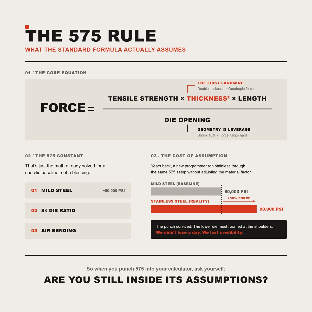
The fuller form behind that 575 shortcut looks like this:
Force is proportional to TENSILE STRENGTH × THICKNESS² × LENGTH ÷ DIE OPENING.
That squared THICKNESS term is the first landmine. Double the thickness and you don’t double force — you quadruple it. Now notice what else is hiding there: DIE OPENING in the denominator. Shrink the V‑DIE OPENING by 10%, and force doesn’t rise politely. It jumps hard because geometry is leverage.
And the 575 constant? That’s just the math already solved for mild steel at roughly 60,000 PSI with an 8× DIE RATIO in air bending. It’s a baseline, not a blessing.
Years back, a new programmer ran stainless — 90,000 PSI TENSILE STRENGTH — through the same 575 setup without adjusting the material factor. The punch survived. The lower die mushroomed at the shoulders. We didn’t lose a day. We lost credibility.
So when you punch 575 into your calculator, ask yourself: are you still inside its assumptions?
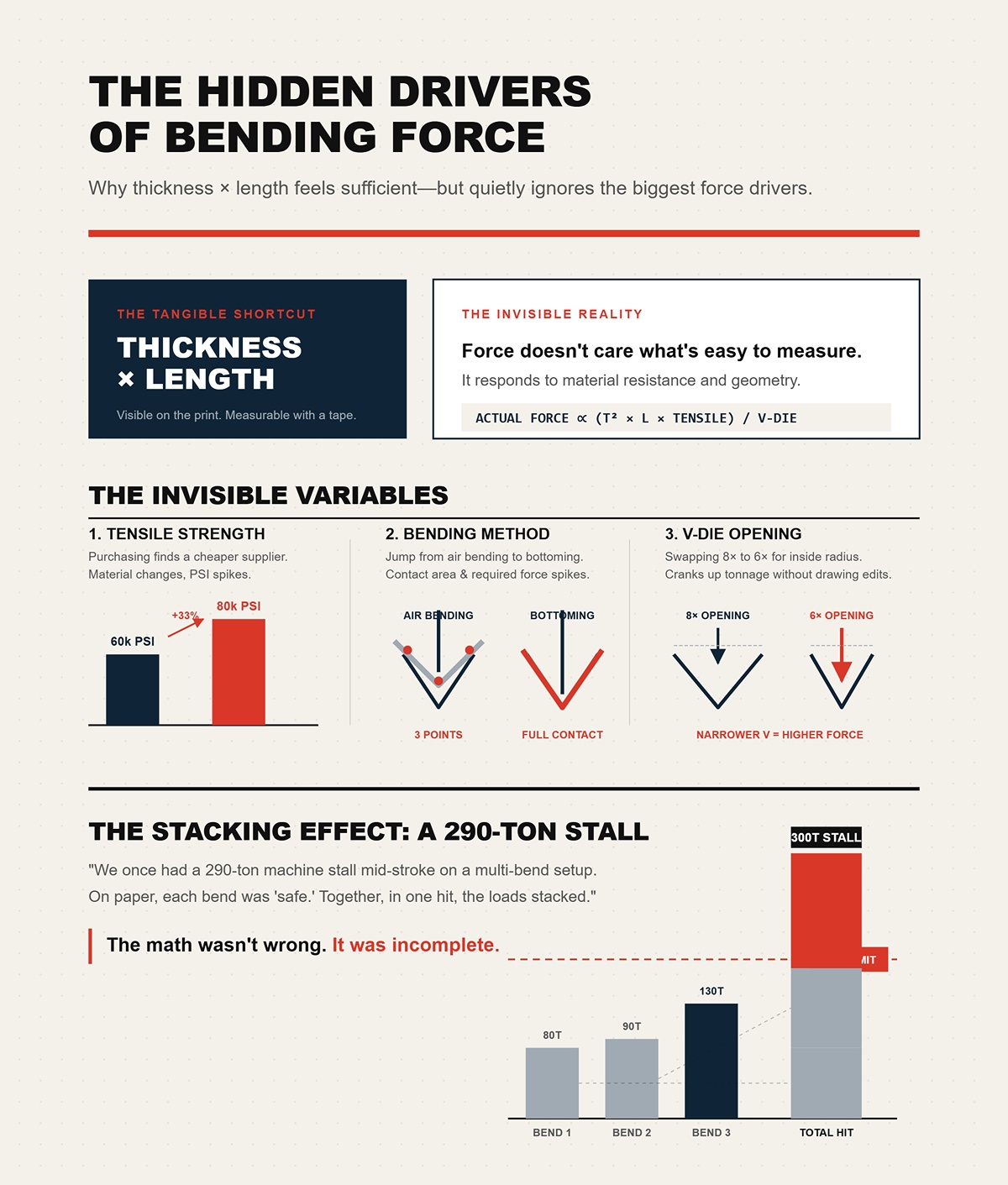
I know why guys love the shortcut. THICKNESS × LENGTH feels tangible. You can see it on the print. Measure it with a tape.
You can’t see TENSILE STRENGTH changing from 60,000 to 80,000 PSI because purchasing found a cheaper supplier. You don’t feel the jump from air bending to bottoming, where contact area — and required force — spikes fast. And you definitely don’t notice when someone swaps from an 8× to a 6× V‑DIE OPENING to control inside radius, effectively cranking up required tonnage without touching the drawing.
Force doesn’t care what’s easy to measure. It responds to material resistance and geometry.
We once had a 290‑ton machine stall mid‑stroke on a multi‑bend setup. On paper, each bend was “safe.” Together, in one hit, the loads stacked. The math wasn’t wrong. It was incomplete.
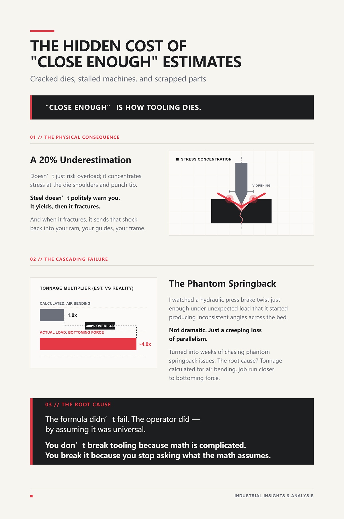
“Close enough” is how tooling dies.
A 20% underestimation doesn’t just risk overload; it concentrates stress at the die shoulders and punch tip. Steel doesn’t politely warn you. It yields, then it fractures. And when it fractures, it sends that shock back into your ram, your guides, your frame.
I watched a hydraulic press brake twist just enough under unexpected load that it started producing inconsistent angles across the bed. Not dramatic. Just a creeping loss of parallelism that turned into weeks of chasing phantom springback issues. The root cause? Tonnage calculated for air bending, job run closer to bottoming force.
The formula didn’t fail. The operator did — by assuming it was universal.
You don’t break tooling because math is complicated. You break it because you stop asking what the math assumes.
A few years back we quoted a run of Quarter‑inch plate in A36, ten feet long. Over a 3‑inch V‑die the sheet penciled out around 139 tons. Clean. Safe on a 150‑ton brake. Same thickness, same length — but the customer wanted a tighter inside radius, so the setup guy grabbed a 1.5‑inch die.
Tonnage jumped to roughly 300 tons.
Nothing else changed. Not THICKNESS. Not LENGTH. Just geometry.
That’s when it stops being “a thickness problem” and starts being a resistance problem. The press brake doesn’t care what the print calls out. It reacts to three things: the material’s resistance to stretching, the leverage your die geometry gives you, and how completely you force the metal into shape.
Miss one, and your 575 shortcut turns into a loaded gun with the wrong cartridge in the chamber.
So if 575 only works inside its assumptions, how do you calculate accurately outside them? You stop treating tonnage like a chart value and start treating it like physics: FORCE ∝ TENSILE STRENGTH × THICKNESS² × LENGTH ÷ DIE OPENING — and then you adjust for bending method.
Three variables. Each one capable of doubling your load without touching the drawing.
Let’s take them one at a time.
A programmer once swapped 60,000 PSI mild steel for 90,000 PSI stainless and left everything else alone in the calculation. Same Quarter‑inch plate. Same die. Same length.
On paper? Identical setup.
In reality, required tonnage increased by 50%.
Here’s why. When you air‑bend, you’re stretching the outer fibers of the material past yield. The higher the TENSILE STRENGTH, the more stress those fibers resist before they plastically deform. The formula doesn’t “care” about the label stainless or carbon. It scales directly with TENSILE STRENGTH.
If your baseline constant assumes 60,000 PSI and you run 90,000 PSI, your multiplier is:
90,000 ÷ 60,000 = 1.5
That’s not rounding error. That’s a 100‑ton job becoming 150 tons.
And stainless adds insult to injury. Its yield strength is often closer to its tensile strength compared to mild steel, and it work‑hardens faster. That means as the bend progresses, resistance climbs. Your brake feels that as load spike near bottom of stroke.
I once watched a brand‑new segmented die set chip along the shoulders because someone trusted a mild‑steel chart for a stainless rush job. The machine was within rating. The tooling wasn’t. We didn’t scrap the part. We scrapped the die.
Stainless isn’t “heavier.” It’s stronger in tension. The formula already told you what to do — multiply by the ratio of actual TENSILE STRENGTH to baseline.
If you don’t adjust that number, you’re not calculating. You’re gambling.
Now let’s talk about leverage.
The common rule is an 8:1 ratio — V-DIE OPENING ≈ 8 × THICKNESS for air bending mild steel. That ratio is baked into most tonnage charts. It’s comfortable. Predictable.
But 575 isn’t a law of physics.
Look back at that Quarter‑inch plate example. A 3‑inch die versus a 1.5‑inch die. Cut the DIE OPENING in half and, because it sits in the denominator of the equation, required force doubles.
Not increases. Doubles.
That’s pure mechanics. A narrower die reduces the span the material bridges, which increases the bending moment required to force plastic deformation. You’ve shortened the lever arm. The brake compensates with force.
Here’s the trap: operators tighten the die to “clean up” the inside radius or control springback. The drawing doesn’t change. THICKNESS doesn’t change. But tonnage climbs fast because geometry changed.
I’ve seen a 90‑ton job turn into a 130‑ton reality because someone swapped to a tighter die to “sharpen the radius.” No alarms. No drama. Just a die set slowly yielding under stress it was never rated for.
And remember — tooling catalogs list max load in tons per foot. Sometimes in short tons. Sometimes metric tons. One is 2,000 pounds. The other isn’t. Mix those up and your safety margin evaporates.
Shrinking the V-DIE OPENING is the fastest way to overload a brake without touching material thickness.
Now we get to the one that blindsides people.
Take that same plate. Same THICKNESS. Same TENSILE STRENGTH. Same DIE OPENING.
Air bend it, and the material contacts only the punch tip and die shoulders. Three points. Limited contact area. Controlled force.
Now bottom it. You force the material into full contact with the die walls. Contact area increases. Friction increases. Required force jumps — often 3× to 4× air‑bend tonnage.
Coin it? You’re no longer just bending. You’re compressing the material at the bend line to eliminate springback. That can push force to 5× to 8× air‑bend requirements.
Same print. Entirely different load case.
I once watched a crew switch from air bending to bottoming mid‑run to chase angle consistency. They didn’t recalc tonnage. The machine didn’t explode. It just started drifting out of parallel under load, subtle frame deflection we chased for weeks before tracing it back to method, not hydraulics.
Air bending is elastic‑plastic deformation with minimal die contact. Bottoming and coining add compressive forming and full die engagement. More resistance. More force.
If you calculate tonnage without specifying BENDING METHOD, you haven’t finished the equation.
And if you haven’t finished the equation, you haven’t earned the right to trust the number.
You’ve seen how TENSILE STRENGTH, V‑DIE OPENING, and BENDING METHOD can swing force like a sledgehammer.
Now you want the actual calculation. Not a chart. Not a “close enough.” A step‑by‑step number you can defend when the ram comes down.
Good. That’s how you stop breaking iron.
The standard constant everyone throws around was derived for air‑bending 60,000 PSI mild steel at a conventional die ratio. It’s a baseline cartridge in a loaded gun. Change the cartridge, the recoil changes. What we’re going to do now is build a formula that makes those cartridges visible — so you know exactly what’s in the chamber before you pull the trigger.
And yes, we’re going to account for TENSILE STRENGTH, actual V‑DIE OPENING, and BENDING METHOD explicitly — not as assumptions hiding inside a magic number.
Let’s start with something concrete.
Take Quarter‑inch plate. 0.250 inches thick. Ten‑foot bend length. Two‑inch V‑die. Air bending.
The air‑bend tonnage formula in imperial form is:
TONS PER FOOT = (TENSILE STRENGTH × THICKNESS²) ÷ (1.33 × V‑DIE OPENING)
That 1.33 isn’t mystical. It comes from beam‑bending mechanics and unit conversion baked around 60,000 PSI baseline steel. It’s geometry and stress distribution collapsed into a constant.
Plug in numbers for 60,000 PSI mild steel:
So:
TONS PER FOOT = (60,000 × 0.250²) ÷ (1.33 × 2.0) = (60,000 × 0.0625) ÷ 2.66 = 3,750 ÷ 2.66 ≈ 1,409 pounds per inch ≈ 16.9 tons per foot
Ten feet long? Multiply:
16.9 × 10 = 169 tons total required force.
That’s air bending. That’s 60,000 PSI. That’s two‑inch die.
Now change nothing but V‑DIE OPENING to 1.5 inches.
Denominator shrinks. Force rises:
(60,000 × 0.0625) ÷ (1.33 × 1.5) = 3,750 ÷ 1.995 ≈ 1,879 pounds per inch ≈ 22.5 tons per foot
Ten feet becomes 225 tons.
Same material. Same thickness. Same length. Half‑inch die change. Fifty‑six tons extra load across the bed.
That’s not a chart quirk. That’s leverage mechanics — bending moment increasing as span decreases.
I once watched a shop try that exact move on a 175‑ton brake. The math said 225 tons. The nameplate said 175. They ran it anyway for a short section near center. The ram crowned permanently. Not dramatic. Just enough that every long bend after that chased angle from one end to the other. We never got that machine straight again.
And we haven’t even touched stainless or bottoming yet.
Notice something else: this formula gives required force. It does not tell you whether your 175‑ton × 10‑foot machine can safely deliver 169 tons across the full ten‑foot span, or only near the center. Machine rating and force demand are different problems. Before you trust the number, you need to know how your press brake distributes load, how its CNC crowning system compensates under stress, and whether its structure is designed for consistent full‑length bending. Modern 100% CNC platforms such as the CN-HAWE press brake are engineered for high‑precision bending and real‑world load control, backed by continuous R&D and testing across press brake and automation systems—so the calculated tonnage can be matched by stable, repeatable machine performance.
First calculate required force. Then compare to real machine distribution limits.
Now let’s talk about the quiet way people lie to themselves.
In metric, the same air‑bend relationship looks like this:
kN per meter = (1.42 × TENSILE STRENGTH (MPa) × THICKNESS² (mm)) ÷ V‑DIE OPENING (mm)
That 1.42 replaces the imperial 1.33 because the unit conversions are already embedded. Different wrapper. Same physics.
Here’s where shops get burned: someone mixes MPa with inches. Or mm with PSI. Or converts tons to metric tons without checking whether the tooling rating was short tons (2,000 lb) or metric tons (2,204 lb).
Two thousand versus 2,204 doesn’t sound like much. It’s 10 percent. On a 200‑ton load, that’s 20 tons of “oops.”
I’ve seen a die stamped for 150 metric tons per meter treated as 150 short tons per foot. That’s not a rounding error. That’s exceeding the tool by a country mile. The shoulders cracked on the third hit.
Units are not bookkeeping. They are force multipliers when you get them wrong.
So here’s the rule: pick a unit system and stay inside it from TENSILE STRENGTH to final tonnage. Only convert once, at the end, if you must.
Now we load a different cartridge.
Suppose your Quarter‑inch plate isn’t 60,000 PSI mild steel. It’s 90,000 PSI stainless.
The clean way to adjust is:
MATERIAL CORRECTION FACTOR (MCF) = ACTUAL TENSILE STRENGTH ÷ 60,000
So:
MCF = 90,000 ÷ 60,000 = 1.5
You don’t “add a little more.” You multiply the entire air‑bend result by 1.5.
Take our earlier 22.5 tons per foot on the 1.5‑inch die:
22.5 × 1.5 = 33.75 tons per foot.
Ten feet?
337.5 tons required.
That’s how a setup that looked like 169 tons in mild steel quietly becomes over 300 tons in stainless with a tighter die.
Now layer method on top.
Air bending multiplier = 1.0 Bottoming can be 4–5× air bend. Coining can reach 8–10×.
If you bottom that stainless job at even 4×:
337.5 × 4 = 1,350 tons.
Same print. Same thickness. Same length.
Different physics.
Here’s the part most formulas hide: the MCF assumes linear scaling with tensile strength. For most structural steels in normal press‑brake ranges, that’s close enough. But high‑strength alloys that work‑harden aggressively can spike load near bottom of stroke. That spike isn’t in the baseline constant. That’s where operator judgment and real‑time load monitoring matter.
I once watched a crew “just try one” on high‑strength plate without recalculating MCF. The brake hit peak pressure before reaching programmed depth. Relief valve screamed. The die survived. The hydraulic seals didn’t.
A unified formula doesn’t eliminate risk. It exposes it. It forces you to see that:
Required Force = (Base Air‑Bend Force from geometry) × MCF × METHOD MULTIPLIER
Only after that do you compare against:
That’s the full chamber check before you pull the trigger.
Next, we’ll run this unified calculation through real shop scenarios — and you’ll see how small variable changes stack into machine‑killing loads faster than your gut expects.
You want to know how fast small changes stack into machine‑killing load?
Good. That’s the right question.
We already built the unified equation — base air‑bend force from geometry, multiplied by MATERIAL CORRECTION FACTOR, multiplied by METHOD MULTIPLIER. Now we’re going to run it on real jobs, the kind that land on your desk at 2:30 on a Thursday when the customer “just needs it by tomorrow.”
Same geometry. Watch what happens when we touch one variable at a time.
Picture a 10‑gauge mild steel bracket. Thickness is 0.135 inches. Bend length is 48 inches. You pick an 8× die, so your V‑DIE OPENING is about 1.08 inches. We’ll call it 1.0 inch to keep the math clean and slightly conservative.
Material is baseline mild steel: TENSILE STRENGTH = 60,000 PSI.
Air bending. No tricks.
Start with the formula:
TONS PER FOOT = (TENSILE STRENGTH × THICKNESS²) ÷ (1.33 × V‑DIE OPENING)
So:
Convert to tons per foot:
821 lb/in × 12 in ≈ 9,852 lb/ft ≈ 4.9 tons per foot.
Your part is 4 feet long:
4.9 × 4 = 19.6 tons total.
Call it 20 tons required force.
That’s boring. That’s safe. That’s what the charts are built around — air bending, mild steel, “normal” die ratio.
And this is where apprentices get cocky.
I once had a kid look at a 25‑ton result like this and say, “We could run that on anything in the building.” Two hours later he tried a similar 10‑gauge job near the edge of the bed on an old mechanical brake. Off‑center loading twisted the ram just enough to crack a punch tip. Cheap lesson. Could’ve been worse.
Baseline jobs lull you into thinking the formula is universal.
It isn’t.
Same print. Same 48‑inch bend. Same 0.135 thickness.
Now the customer switches to 304 stainless. Typical TENSILE STRENGTH? Around 90,000 PSI.
And the operator decides to “tighten the radius” with a 0.75‑inch V‑DIE OPENING instead of 1.0.
That’s two variables changed. Watch the stack.
First, geometry with new die:
Convert:
1,642 × 12 ≈ 19,704 lb/ft ≈ 9.85 tons per foot.
Four feet long:
9.85 × 4 ≈ 39.4 tons.
The “20‑ton job” just became a 40‑ton job.
Nothing exotic happened. We didn’t double thickness. We didn’t change length. We increased TENSILE STRENGTH by 1.5× and shrank V‑DIE OPENING by 25%.
Force doubled.
This is exactly how a shop walks off a cliff. I’ve seen a 90‑ton job turn into a 130‑ton reality because someone swapped to a tighter die to “sharpen the radius.” The machine didn’t complain. The tooling did. Hairline cracks in the die shoulders that showed up three weeks later under a heavier run.
“But 575 isn’t a law of physics.”
No. It’s a shortcut built around mild steel and generous dies. Change either, and the lever arm changes. The bending moment rises because you shortened the span and increased material resistance at the same time.
Now you’re staring at 40 tons instead of 20.
Still comfortable?
We stay with the stainless setup above: 0.135 thick, 48 inches long, 0.75‑inch die, TENSILE STRENGTH = 90,000 PSI.
Air bending required about 40 tons total.
Now switch methods.
Bottom bending — where the punch drives the material into full contact with the die angle — typically requires at least 2× the air‑bend force for the same geometry. That’s not opinion. That’s material being forced past elastic recovery into plastic conformity with the die walls.
So:
40 tons × 2 = 80 tons.
Minimum.
Some materials, especially work‑hardening stainless, climb beyond that as you approach bottom of stroke because contact area increases rapidly and friction spikes. Your load curve steepens near the bottom — right where machines see peak hydraulic pressure.
The job that looked like a comfortable 20 tons in mild steel air bending is now an 80‑ton stainless bottoming operation.
Four times the baseline.
Same drawing.
I watched a crew bottom‑bend what they thought was a 50‑ton stainless job on a 60‑ton brake. The air‑bend math was fine. They forgot the METHOD MULTIPLIER. The machine hit relief pressure mid‑stroke and stalled. They tried again. The die survived. The ram gib clearances didn’t. That brake never tracked straight after.
Here’s the pattern you’re supposed to see:
These aren’t small corrections. They compound.
And the machine doesn’t care what the chart said. It only feels force across the bed — distributed, concentrated, off‑center, whatever you feed it.
So when a print changes material, or someone grabs a tighter die, or production decides to bottom instead of air bend to “lock the angle,” you don’t guess.
You rebuild the load from scratch. Then you compare it to real machine capacity across that exact bend length — not the nameplate fantasy.
Because the formula is a loaded gun. Safe when you know exactly what’s in the chamber.
Deadly when you assume every cartridge is the same.
You ran the numbers. You adjusted for TENSILE STRENGTH, tightened the V‑DIE OPENING, multiplied for bottom bending. The calculator says 80 tons.
So how do you know your 100‑ton brake can actually survive that load across 6 feet without twisting itself into scrap?
Given that CN-HAWE’s product portfolio is 100% CNC-based and covers high-end scenarios in laser cutting, bending, grooving, shearing, if the next step is to speak with the team directly, Contact us fits naturally here.
Here’s the part nobody puts in the chart: the formula assumes perfect tooling, perfectly distributed load, and perfectly behaved material. That’s a fantasy. Real shops run worn dies, off‑center parts, mixed grain sheets, and machines that only deliver full rated capacity over part of the bed length. A 175‑ton × 10‑foot brake isn’t 175 tons everywhere; push that full force across the entire bed and you’ll crown the frame unless you understand how the load spreads.
The math gives you a number. The machine feels a pattern.
That gap is where tooling gets shattered.
I once watched a crew bend quarter‑inch plate near the far end of a long bed because “there was room.” The calculated TONS PER FOOT was fine. What they didn’t respect was that full rated tonnage was only safe over about 60% of that bed length. The frame took a set. Permanent crown. That brake never hit parallel again without shims and prayers.
A sharp die shoulder concentrates force along a clean line of contact. That’s what your equation assumes.
Now picture a die that’s run thousands of hits on stainless. The once‑crisp radius at the DIE SHOULDERS has flattened. Instead of a narrow contact line, you’ve got a smeared contact patch. More surface area. More friction. More resistance to material flow.
Force climbs.
Not because TENSILE STRENGTH changed. Not because THICKNESS changed. Because friction and contact geometry changed, and your formula doesn’t have a slot for “beat‑up tooling.”
Hypothetically — and I’m labeling this as a shop estimate, not a lab study — I’ve seen identical jobs pick up what felt like 15–30% more required force when swapped from fresh precision‑ground dies to tired production dies. The press tone changes. Hydraulic pressure creeps higher near bottom of stroke. The angle comes in stubborn.
The calculator still says 40 tons.
The machine says otherwise.
I’ve destroyed a $4,000 precision die set by trusting clean math over dirty steel. The numbers were right. The tooling wasn’t. Micro‑cracks started at the worn shoulder and spidered out under a heavier follow‑up job. We found them when a corner snapped mid‑bend and scarred a customer’s part.
You can’t plug wear into a neat THICKNESS² term. You have to look at the metal in front of you and ask what it’s been through.
Total tonnage is only half the story.
Press brakes are rated in tons across a length — tons per foot, tons per meter. That rating assumes distribution. Spread the load evenly, and the frame carries it like a bridge carries traffic.
Now stick a narrow part under a sharp, small‑radius punch near one end of the bed.
You didn’t exceed total AVAILABLE TONNAGE. But you spiked TONS PER FOOT in one short section and shifted it off center. The ram and bed don’t see “80 tons total.” They see a concentrated bending moment trying to twist them apart.
This is the pointy punch problem.
Custom punches with tight noses and narrow V‑dies shrink the contact zone. The same calculated force now flows through less steel in the tooling and less width in the machine structure. Stress rises fast because stress equals force divided by area. Cut the area, double the stress.
I’ve seen a 90‑ton job turn into a 130‑ton reality because someone swapped to a tighter die to “sharpen the radius.” The total force increase was obvious. What wasn’t obvious was the local spike at the punch tip. The tip chipped. Then it cratered. Then it started embossing that crater into every part until we caught it.
And remember that bed‑length limit. Many machines safely deliver full rating over roughly 60% of the bed. Concentrate your load in 2 feet at the edge and you are no longer living in the catalog’s happy place.
Your calculation might be correct in total tons.
It can still be wrong for your frame.
Two sheets. Same grade stamp. Same TENSILE STRENGTH on paper.
Bend one parallel to the rolling direction. Bend the other perpendicular.
They do not behave the same.
Rolling elongates grain structure. When you bend across the grain, you’re fighting that structure differently than when you bend with it. Springback shifts. Required overbend changes. Sometimes the force curve near bottom of stroke steepens because the material resists compression differently along that orientation.
Your formula treats steel like isotropic clay — same properties in every direction.
It isn’t.
And then there’s work hardening. Stainless in particular builds strength as it deforms. The more you push it, the more it resists. That means the last few degrees of a bottoming operation can demand disproportionately higher force than the early stroke predicted. The load cell — if you’re smart enough to watch one — will show that spike.
I once split a punch on a long stainless run because we rotated sheets mid‑batch to optimize scrap. Half the parts bent fine. The rotated sheets needed more overbend and hit harder at the bottom. The tooling saw the difference even if the print didn’t.
Material has memory. Your calculator doesn’t.
Which brings us to the question you should be asking before every serious run: not “What’s the theoretical tonnage?” but “What is the maximum TONS PER FOOT my machine can deliver safely, over this exact length, in this exact position, with this exact tooling condition?”
That’s not a formula problem anymore.
That’s an operator validation process.
You’ve done the calculation. You adjusted for TENSILE STRENGTH, corrected for DIE OPENING, multiplied for bottoming instead of air bending. Good.
Now forget the pride you feel about that spreadsheet.
Because the machine doesn’t care how elegant your TONS PER FOOT number looks. It cares where that force is applied, how long it’s applied, and whether the steel frame under that ram can carry it without yielding. This is where we stop being mathematicians and start being operators.
Here’s the protocol. Not theory. Not catalog fluff. A sequence.
First: compare TONS PER FOOT to what your machine can safely deliver over the exact length you’re bending. Second: build a real safety margin that accounts for method changes and unknowns. Third: make the first hit a diagnostic tool, not a leap of faith.
I once watched a 175‑ton brake take a permanent crown because someone trusted total tonnage over distribution. The math said 160 tons total. The machine saw 40 TONS PER FOOT stacked near the end of the bed. Steel yielded. It never came back.
A brake rated at 100 tons over 10 feet is not a 100‑ton machine everywhere.
It’s a 10 TONS PER FOOT machine — assuming even distribution across the working length.
Now take a 2‑foot part and park it 12 inches off the left side. If your calculation says 25 TONS PER FOOT, you are asking that section of the ram and bed to carry 50 tons concentrated in one small zone. The other eight feet are doing nothing.
Catalog ratings assume distribution. Frames are designed like bridges — load spread across span. Concentrate it, and the bending moment in that local section spikes. The deflection isn’t linear anymore. It’s geometric.
And here’s where operators get fooled: total AVAILABLE TONNAGE might be under the machine’s max, but local STRESS — force divided by area — exceeds what that ram segment can handle.
I’ve seen a short stainless bracket, barely two feet long, permanently twist the left side of a bed because the operator centered the backgauge fingers instead of the part. The machine didn’t exceed total TONNAGE. It exceeded structural common sense.
So you validate like this:
If your per‑foot demand exceeds the machine’s per‑foot capacity in that location, you are not “a little aggressive.” You are structurally overloading.
Even if your numbers fit on paper, you don’t run a brake at 100% of rated CAPACITY.
You don’t redline a diesel every shift either.
Why 80%? Because your formula doesn’t know everything. It doesn’t see grain direction, die wear, friction changes, temperature swings in hydraulic oil, or the difference between a die rated in short tons per foot versus metric tons per meter at a different angle. A die stamped 60 in one catalog isn’t always stronger than one stamped 46 in another unless you convert the units and rating conditions.
Here’s the mechanism: as you approach maximum frame load, deflection increases nonlinearly. Small additional force creates disproportionately larger structural strain. That’s when crowning systems max out. That’s when pins start fretting. That’s when micro‑cracks begin.
Now add bending method.
Air bending at baseline? Fine — 80% rule makes sense. Bottoming at 1.5× force? Your margin just shrank. Coining at 5×? The 80% rule becomes meaningless because the load spike at bottom of stroke can exceed rating instantly.
I once watched an operator bottom a part that had been air‑bent all week because “the angle was drifting.” That method change pushed effective REQUIRED FORCE past rated CAPACITY even though the original air‑bend math was safe. The ram seals didn’t fail that day. The frame yielded over time. Six months later we were shimming around a permanent deflection.
Safety margin isn’t cowardice. It’s accounting for what your formula cannot see.
This is where the loaded gun metaphor gets real.
The formula tells you what should happen. The first hit tells you what is happening.
You validate in stages:
If the load climbs faster than predicted by your calculated FORCE CURVE, stop. Something changed — maybe the actual TENSILE STRENGTH is higher than spec, maybe the DIE OPENING is effectively smaller due to wear, maybe you’re unintentionally bottoming.
Digital load sensors today will show you deviations that the old charts never could. If your calculated demand was 20 TONS PER FOOT and the machine reports 26 climbing hard at the last few degrees, that’s not “close enough.” That’s a 30% miss.
I destroyed a set of segmented punches early in my career because I trusted the number more than the sound. The pressure gauge was telling me the load curve was steeper than it should’ve been. I pushed through. The segment split at the keyway. The math had been right for air bending. The machine was bottoming because the depth stop was off by a hair.
Here’s the one thing you carry forward:
The formula is not the authority. It’s a hypothesis.
The machine — its frame rating, its per‑foot limits, its live load feedback — is the experiment. If those two disagree, you believe steel over theory.


