

By noon the new urethane pads were already tattooed with shiny crescent scars. Ten-foot brake. Quarter-inch mild steel. Fresh tooling bolted in at 7 a.m., confidence high. By second shift the operator was muttering about “another bad batch.”
Same slip. Same angle drift. Different pads.
When a brand-new pad fails in hours, you’re not looking at bad luck. You’re looking at a crime scene. The question isn’t “Which supplier messed up?” It’s “What in the force path just murdered another sacrificial part?”
I’ve watched shops treat pads like fuses. Something slips, angles wander, material creeps—so they swap the soft stuff and call it maintenance. It feels decisive. It costs less than downtime. And it avoids the uncomfortable possibility that the machine itself is lying to you.
But sacrificial components tell stories. When they wear gradually and evenly, that’s abrasion doing its honest work. When they split, crush, glaze, or delaminate in patches, that’s load concentration, timing error, or misalignment talking through rubber and steel. Shop floor forensics.
So how do you tell the difference between a pad that lived its life and one that got executed?
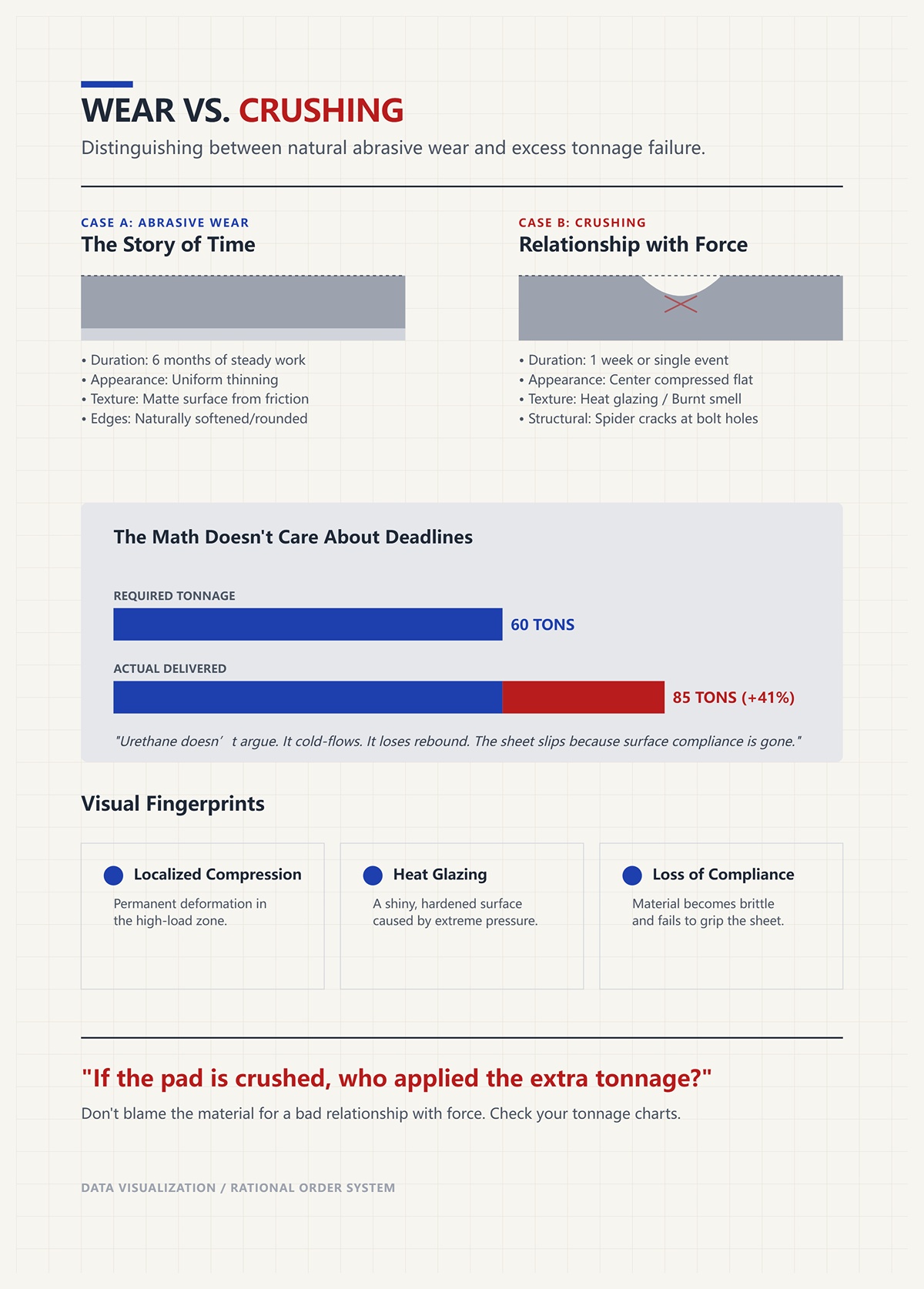
Pull a pad that’s done six months of steady work. You’ll see uniform thinning. Edges softened. Surface matte from friction. That’s abrasive wear—material slowly sacrificed as designed.
Now pull one after a week and find the center compressed flat as a coin, edges still proud, maybe even spider cracks around bolt holes. That isn’t wear. That’s crushing.
The math doesn’t care about your deadline. If your bend requires 60 tons and you’re delivering 85 because your tonnage chart wasn’t updated for actual material thickness, the pad absorbs the overage. Urethane doesn’t argue. It cold-flows. It loses rebound. Next cycle, the sheet slips because the surface compliance is gone.
Excess tonnage leaves fingerprints: localized compression, heat glazing, sometimes a faint burnt smell. Abrasion leaves a story of time. Crushing tells you about one bad relationship with force.
If the pad is crushed, who applied the extra tonnage?
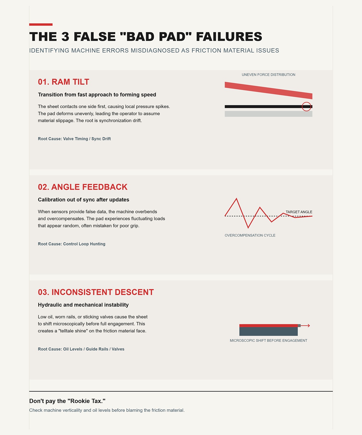
I’ve seen three repeat offenders.
First: ram tilt during the transition from fast approach to forming speed. The sheet contacts one side first, pressure spikes locally, and the pad deforms unevenly. To the operator, the part slips. To the pad, it’s a one-sided assault. The root is valve timing or synchronization drift, not friction material.
Second: angle feedback out of calibration. Modern brakes can correct within half a degree in fractions of a second—if the sensors are telling the truth. After a software update or skipped recalibration, the machine overbends, compensates, overcompensates. The pad sees fluctuating loads that look random. You blame grip. The real culprit is a control loop hunting in the dark.
Third: slow or inconsistent descent from hydraulic issues—low oil, worn guide rails, a sticking fill valve. One symptom, half a dozen mechanical causes. The sheet shifts microscopically before full engagement, and you get that telltale shine on the pad face. Rookie tax is ordering friction material before checking oil level and rail verticality.
When three different machine errors can produce the same “slip,” why assume the soft part is guilty?
A catalog calls it universal: one compound, broad hardness range, fits multiple dies. Fine for agricultural brackets.
Now put that same pad under tight-tolerance aerospace parts with mixed alloys in the same shift. Aluminum at 1/8 inch in the morning, high-strength steel after lunch. Different springback. Different required tonnage. Different surface energy against the pad.
Uniform material in a variable force environment is a gamble.
If you tune tonnage and alignment precisely for each job, you can run a broader pad spec safely. If you don’t, you’re asking one hardness and one thickness to forgive every setup shortcut. It won’t. High-precision work exposes the myth because the margin for error is thinner than the pad itself.
So when a “universal” pad keeps failing on only certain jobs, is it really universal—or is your process not?
Let’s say a pad set costs a few hundred dollars and an hour of labor to swap. Easy decision. Harder decision is two hours with a dial indicator, pressure verification, sensor recalibration, and a dry run without material.
One feels productive. The other feels like admitting you might be the problem.
But when failures cluster—multiple pads across different jobs in a month—that’s not random wear. That’s process drift. In manufacturing plants that track pad integrity upstream, defects show up in batches because the pressing cycle went out of spec. Same logic applies here. Repeated pad death is rarely coincidence.
Every replacement without diagnosis is just resetting the countdown clock. You’re paying in urethane instead of attention.
And if force misuse keeps writing the same story on fresh pads, what happens when we finally put the tonnage numbers under a light?
Last spring I stood at a Ten-foot brake rated for 150 tons, looking at a pad that had been in service for nine days. The center was crushed flat, edges untouched, bolt holes starting to oval. The operator swore the job was “well within capacity.” Quarter-inch A36 over a 2-inch V-die.
On paper that’s 19.7 tons per foot. Across ten feet, 197 tons. The math doesn’t care about your deadline. You were 47 tons past the machine’s rating before you even hit bottom.
Switch to a 3-inch V-die and the required force drops to 13.9 tons per foot—139 tons total. Same material. Same length. Different die width. Now you’re inside the machine’s envelope and the pad lives a normal life.
That’s how you verify tonnage before you crush another insert: calculate per-foot force for the actual thickness and V-opening, multiply by the real bend length, and compare it to rated capacity across the working span. Not the sticker on the side. The distributed load across the bed.
Because if your required tonnage exceeds either the brake’s rating or the pad’s compressive limit, failure isn’t a possibility. It’s a schedule.
And most shops aren’t even running the numbers that way.
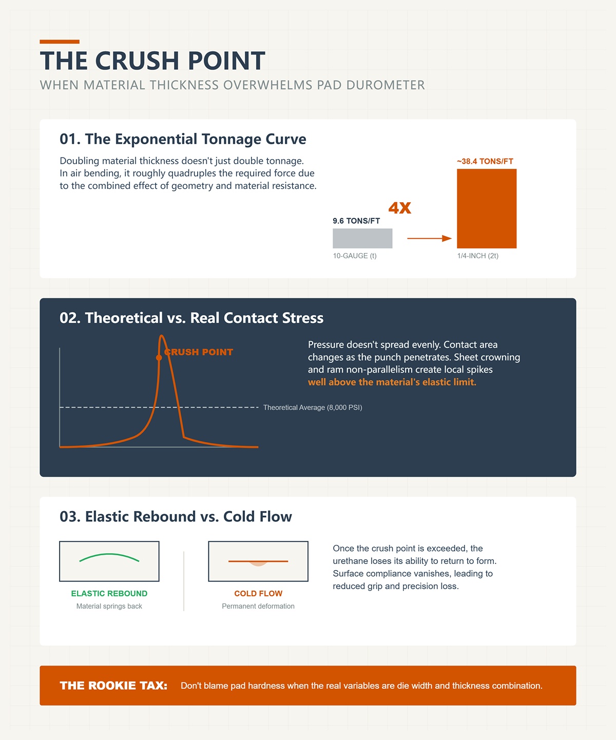
I’ve watched a shop jump from 10-gauge to 1/4-inch and assume tonnage “goes up a bit.” It doesn’t. Doubling thickness roughly quadruples required tonnage in air bending. That’s geometry and material resistance working together.
If 10-gauge needs about 9.6 tons per foot over a 1-inch V, and you double thickness, you’re not at 19. You’re closer to four times the original demand, depending on die width. That’s the curve.
Now picture a urethane pad rated hypothetically at 8,000 psi compressive strength. You lay 197 tons across ten feet and assume it spreads evenly. It doesn’t. Contact area changes as the punch penetrates, especially if the sheet crowns or the ram isn’t perfectly parallel. Local pressure spikes well above the average.
That spike is your crush point. Not when the catalog says the pad “should” fail. When the real contact stress exceeds the material’s ability to rebound elastically. After that, the urethane cold-flows. It doesn’t spring back. Next cycle, your grip is reduced because your surface compliance is gone.
And here’s the trap: you blame pad hardness when the real variable was die width and thickness combination. Rookie tax.
But even if your tonnage is technically “within capacity,” why do some pads still walk out of position?
I watched an operator bump tonnage up 10% because a sheet slipped during forming. His logic was simple: more force, more grip.
Under moderate pressure, urethane deforms just enough to conform to surface irregularities. That increases real contact area and friction. Push past a certain point and you over-compress the surface layer. It hardens locally, smooths out, sometimes even heat-glazes. Now your real contact area drops.
You’ve increased nominal pressure but reduced effective friction.
Add in a slight ram tilt—one side contacting milliseconds before the other—and you create a lateral force component. The pad, now over-compressed and less compliant, can’t absorb it. The sheet “walks.” The operator adds more tonnage. The pad dies faster.
But sacrificial components tell stories. When you see polished streaks in one direction, that’s not random wear. That’s lateral shear under excessive normal load.
So if pressure alone isn’t the full story, what happens when the die itself concentrates force where no polymer can survive?
Take that same 1/4-inch A36. Over a 1.5-inch V-die, required tonnage jumps to roughly 30 tons per foot. Over ten feet, that’s 300 tons. Double the capacity of our 150-ton brake.
Now imagine you’re not running full length. You’re bending three feet in the center. The machine still delivers force through the central portion of the ram. The load per foot skyrockets locally, and you’re under 60% of the side-frame span where deflection characteristics change. Frame flex shifts load toward the center.
What the chart called “acceptable” for a full-span bend becomes abusive in a short, centered bend. That’s how you get pads crushed in the middle while the ends look new.
Bottoming multiplies the insult. It can require roughly four times the air-bend tonnage. Coining can demand ten times. If you mistake a bottoming setup for air-bend tonnage and leave the pad in place, you’ve just signed its death certificate.
This isn’t about owning a big brake. Excess capacity rarely hurts pads because you only apply what the job demands. The real danger is undersized dies on undersized machines, chasing tight radii and paying in urethane.
So when you pull a deformed pad, how do you read it like evidence instead of trash?
A pad crushed uniformly across its length tells me you exceeded global tonnage. The whole system was overloaded. That’s a straight math error.
A pad crushed only in the center tells me localized overload—short bends, narrow V, or frame deflection concentrating force mid-span.
Diagonal compression? Ram tilt or uneven hydraulic synchronization.
Heat-glazed surface with minimal compression? Excess pressure chasing friction, likely combined with slight material movement.
Modern brakes can correct within half a degree in fractions of a second—if the sensors are telling the truth. If angle feedback is drifting, the control system may be overdriving tonnage to hit a target angle that was never wrong to begin with. The pad absorbs the correction.
This is shop floor forensics. You don’t start by ordering harder inserts. You start by recalculating tonnage per foot, verifying die width against thickness, checking actual bend length against rated span, and confirming forming method—air bend, bottom, or coin.
Because once your applied tonnage exceeds what the pad and the frame can distribute safely, the insert isn’t the weak link.
It’s the witness.
You want a repeatable pre-job verification process that prevents pad failure before the first bend?
Start by assuming the pad is innocent.
Once you’ve verified tonnage per foot, die width-to-thickness ratio, bend length versus rated span, and confirmed you’re air bending—not accidentally bottoming—the next variable isn’t “harder pad.” It’s the sheet itself. Because press brake pads are sacrificial components of a larger mechanical system, and that system includes the metallurgy sitting between punch and die. Ignore that, and you’re not solving failure. You’re scheduling it.
The math doesn’t care about your deadline. Stainless and aluminum can share thickness, share bend angle, share tooling—and demand completely different force paths. If your process checklist ends at “machine and die look right,” you’ve only cleared half the crime scene.
So what does the material do to your pad that the pad can’t undo?
Run 1/8-inch 5052 aluminum all day over a moderate V, and a mid-durometer urethane pad behaves like a hero. It conforms, increases real contact area, stabilizes the sheet. You get clean bends and minimal marking.
Swap in 304 stainless at the same thickness and geometry, and suddenly the pad starts polishing, glazing, maybe even creeping out of position.
That’s not mood. That’s metallurgy.
Aluminum yields early and flows. Stainless resists, work-hardens, and demands higher forming stress for the same geometry. Higher forming stress means higher reaction force back into the pad. Even if your global tonnage is within capacity, the contact pressure at the punch-pad interface climbs because stainless doesn’t “give” as willingly.
Urethane thrives on controlled deformation. Stainless forces it toward its compressive limit faster. Blame the pad, and you’re paying rookie tax on misunderstood metallurgy.
But resistance isn’t the whole story. Stainless also springs back harder.
Which means the fight isn’t just during the downstroke.
Springback is elastic recovery after unloading. Every material has memory. Stainless has a long one.
In air bending, you intentionally overbend to compensate for that recovery. The pad’s elasticity can help stabilize the sheet during forming, but it cannot erase elastic strain stored in the metal. If stainless wants to open two degrees, it will—unless you change geometry or method.
Here’s the uncomfortable part: narrowing the V-die from, say, a 12:1 to an 8:1 width-to-thickness ratio can cut springback dramatically, independent of pad material. Bottom bending reduces it further because you’re forcing more plastic deformation into the bend zone. Geometry beats polymer.
So if you’re asking a urethane pad to “hold” stainless in angle while using a wide V meant for aluminum, you’re asking elasticity to fight material memory. It can’t win that fight for long.
The pad compresses. The sheet still opens. The operator bumps tonnage. Now you’re back to crushing a sacrificial component to compensate for a geometry choice.
And when that doesn’t fix the angle, what’s the next instinct?
Harder pad.
Durometer is a measure of hardness in elastomers. Higher number, stiffer pad.
It sounds logical: stainless is tougher, so use a tougher pad.
The math doesn’t care about your logic.
A harder pad deforms less under load. Less deformation means less real contact area between pad and sheet. Friction doesn’t scale linearly with nominal pressure; it depends on actual micro-contact. When you stiffen the interface, you reduce conformity. Now the sheet is more likely to micro-slip during the stroke.
Micro-slip shows up as inconsistent bend angles.
Here’s the twist most shops miss: a harder pad can increase peak contact stress because the load is distributed over fewer microscopic contact points. That local stress can push the material closer to its elastic limit during forming, increasing variability in springback. Your “stronger” setup produces softer, less repeatable bends.
Tonnage vanity meets durometer vanity.
And if your hydraulic system has even slight instability—trapped air, lagging valves—that stiffer pad transmits those force oscillations directly into the sheet instead of damping them. What looks like “pad too soft” was actually a system that needed compliance to stay stable.
So hardness isn’t a universal upgrade. It’s a tuning parameter within a force system.
Which leaves one more quiet saboteur.
You can calculate tonnage. You can choose die width. You can match durometer to alloy.
Then someone wipes the sheet with the wrong oil.
Light forming lubricants, mill oils, even residual coolant change the coefficient of friction at the pad-sheet interface. Not by a little. By enough that your carefully selected compliance no longer translates into grip. The sheet shifts during the downstroke, and the pad shows lateral polishing. You blame elasticity.
But sacrificial components tell stories.
If the wear pattern is smooth and directional without deep compression, I start looking at surface condition, back gauge finger wear, and clamping force before I ever call the pad supplier. Mechanical grip assumes clean contact. Chemical films rewrite that assumption.
And here’s the quiet truth: no pad compensates for a slippery interface combined with marginal clamping. That’s not an elastomer problem. That’s process control.
So your repeatable pre-job verification process can’t stop at tonnage charts and die selection. It must include material grade, temper, expected springback, chosen V ratio, pad durometer, and surface condition—checked before the first cycle.
Because once you accept that pads operate inside a material system, the real question isn’t “Which pad is strongest?”
It’s which pad belongs in this exact combination of alloy, geometry, force, and surface state.
A supervisor once handed me two crushed urethane blocks and asked which “brand” I preferred. Both had failed in under two weeks. One was mushroomed at the center. The other was split clean along one edge. Same press. Same operator. Different jobs.
That’s your pre-job framework, if you know how to read it.
The math doesn’t care about your deadline. Before you pick surface engineering—block, film, insert, texture—you lock down four variables: calculated forming tonnage for the alloy and thickness, selected V-opening and method (air vs. bottoming), machine crowning and parallelism, and surface condition of the sheet. Only after the pressure path is disciplined do you choose what sits between punch and die. Otherwise you’re paying rookie tax for tonnage vanity and calling it “premium pads.”
Surface solutions don’t fix pressure distribution. They only behave predictably inside it.
So which one belongs where?
Picture 3 mm 5052 aluminum covers, cosmetic face out, 2,000 parts per shift. The shop wants zero witness marks. They drop in a solid urethane die block and air-bend into it. Parts look clean. Tonnage gauge reads lower than with steel. Everyone relaxes.
Urethane is elastic. It deforms, increasing contact area and lowering peak contact stress. That’s why required tonnage often drops compared to steel V-dies for the same nominal geometry. The load spreads through the polymer instead of concentrating at two die shoulders.
But here’s the catch I’ve seen more than once: polyurethane is not steel. Under repetitive high-volume cycling, especially with deeper bends, it creeps and fatigues. Shops bending 12-gauge cold roll on urethane blocks learn this fast—the blocks glaze, compress permanently, then crack. Steel dies might last decades in that duty. Urethane will not.
And chemistry matters. Swap a more flexible TDI-based urethane for a stiffer MDI type without recalculating deflection and cure behavior, and you can turn a cushioning solution into a brittle one. I’ve seen blocks chip at the corners because the “upgrade” was too rigid for the actual strain they were absorbing. That’s not a bad block. That’s mismatched elasticity amplifying a tonnage calibration error.
High-volume and urethane can coexist—but only when the bend depth, material yield strength, and stroke frequency are inside the block’s fatigue envelope. That requires knowing your actual forming force, not what the nameplate says.
If the block is crushing in the center, ask why your pressure is peaking there.
Now switch scenes. Thin 304 stainless, 1.5 mm, tight angular tolerance—plus or minus half a degree—and a brushed finish that cannot be marred. The team chooses a synthetic bending film between sheet and die.
On the first run, angles come out overbent by almost a degree. Operator bumps the ram up. Inconsistency creeps in.
What changed? Thickness.
A 0.8 mm film effectively narrows your V-opening. If you were running a 16 mm V for 3 mm material, adding that film changes the geometry. The sheet now sees a smaller die width, increasing forming stress and reducing springback. If you don’t adjust for that, you are not “protecting the surface.” You are altering the pressure distribution and pretending you didn’t.
The math doesn’t care about your deadline.
Films shine when precision outweighs cushioning. They add minimal compliance compared to solid urethane blocks, so angle repeatability can be tighter—provided you recalculate effective die width and tonnage. Ignore that, and the film becomes a hidden variable that distorts your force path. Over-pressing to chase angle through a film is just a quieter form of overload.
So films demand discipline. They are not drop-in protection. They are geometry modifiers.
Which makes you wonder how “quick change” systems behave when thickness and stack-ups shift mid-shift.
I’ve watched a shop swap from mild steel brackets to high-strength low-alloy parts in under ten minutes using modular urethane inserts. Fast. Clean. Impressive.
By the end of the week, the inserts showed uneven wear—crushed on the left third of the bed.
Quick change is only quick if your machine geometry is honest. Modular systems rely on consistent seating and even clamping. A few thousandths of misalignment across a long bed means the insert stack is carrying uneven load. Unlike a monolithic die, segmented inserts telegraph that imbalance through differential compression.
But sacrificial components tell stories.
When only certain modules collapse early, that’s shop floor forensics pointing at ram tilt, poor crowning compensation, or uneven bed wear. Modern brakes can correct within half a degree in fractions of a second—if the sensors are telling the truth. If they’re not calibrated, your modular convenience becomes a distributed failure map.
Modular inserts are excellent when product mix is high and tonnage is recalculated per job. They are expensive padding when shops assume yesterday’s setup applies to today’s alloy.
If your inserts are aging unevenly, the issue isn’t the insert catalog.
It’s the force path.
Which brings us to friction—the quiet saboteur most people try to fix with texture.
Consider galvanized sheet with residual mill oil. During the downstroke, the sheet creeps a millimeter before biting. Operator blames “slippery material” and orders textured inserts with anti-slip coating.
Friction is not just roughness. It’s real area of contact under load. A textured insert increases mechanical interlock, yes—but it also concentrates contact stress at the asperity peaks. Under high tonnage, those peaks wear first. If your clamping force and back gauge support are marginal, texture masks the slip temporarily while accelerating insert wear.
Clean the sheet. Verify clamp pressure. Confirm back gauge alignment. Then decide if texture is needed.
Anti-slip solutions are appropriate when surface condition cannot be controlled—oily blanks from upstream, coated materials, high cosmetic demands with minimal marking allowed. But they must be matched to actual forming stress. Overload them, and the coating becomes the new sacrificial witness.
A pad, block, film, insert, or texture is never a magic eraser for bad force distribution. It is the last element in a chain that starts with alloy choice, die geometry, and calibrated tonnage.
If you choose surface engineering before you verify the pressure path, you’re not solving a problem.
You’re postponing it.
You want a systematic way to verify pressure distribution before you order another box of premium pads.
Good. Because until you check alignment, crowning, and parallelism under load, you’re diagnosing blindfolded.
I’ve stood next to a ten-foot brake where the center angles were perfect and the ends were wandering by two degrees. Everyone blamed the pads. The pads were new, high-durometer, expensive enough to make accounting nervous. But sacrificial components tell stories. The wear pattern was heavier on the left third, polished in the middle, barely touched on the right. That isn’t a material problem. That’s geometry confessing.
Surface engineering is downstream. Geometry is upstream.
If you don’t verify the frame and ram are delivering force evenly across the bed, every pad you install is just chalk at the end of a crooked cue stick. So let’s walk the crime scene properly.
Five thousandths of an inch doesn’t scare most people.
It should.
The math doesn’t care about your deadline. Over a 120-inch bed, 0.005 inches of tilt means one side of your die closes sooner. That side takes load first. Urethane doesn’t share load like steel; it compresses where it’s hit. So the early-contact side carries disproportionate tonnage until the rest of the ram catches up. That’s not cushioning. That’s localized overload.
Hypothetical, but realistic: you’re forming 1/8-inch 5052 across eight feet. Required tonnage says 60 tons. Because of misalignment, the left 30 inches effectively see the contact first and absorb a spike—maybe not the full 60, but a sharp percentage of it—before the rest engages. That spike exceeds the compressive fatigue limit of the pad in that zone. After a week, that section mushrooms and cracks. The rest looks fine.
Rookie tax.
Modern CNC brakes will flag Y-axis deviations tighter than a millimeter fraction across the stroke, and they should. If your mechanical zero is off, if your guides are worn, if your gibs have clearance you can feel with a fingernail, you’re not bending evenly. You’re shaving life off one side of every sacrificial layer you install.
And when the pad fails asymmetrically, the machine just told you where to look.
So why do some beds eat pads in the center while the ends stay fresh?
Picture a long bed under heavy load.
Steel deflects. Frames breathe. That’s not a flaw; it’s physics. Without crowning—intentional upward compensation in the bed or ram—the center sags under tonnage. The die opening effectively narrows there. The sheet sees higher forming stress in the middle than at the ends.
Now add a compliant pad.
The center compresses harder because it’s seeing higher stress. Over time, you get a trough worn into the pad’s middle while the ends still look factory-new. Operators call it “bad batch material.” I call it uncorrected deflection.
High-end machines with rigid frames and real-time angle feedback reduce this drama. They minimize deflection so aggressively that crowning becomes subtle, sometimes almost invisible in day-to-day work. But older brakes? Long beds over three meters? Mechanical wedge crowning earns its keep there because it counters sag with rigid, predictable compensation instead of hydraulic drift.
Pads don’t fix sag. They conform to it.
If the center is dying first, the frame is talking.
But here’s the catch: checking crowning at rest tells you almost nothing about what happens when 100 tons hit the bed.
So how are you measuring parallelism?
Most shops check alignment with the ram parked and the machine quiet.
That’s half the crime scene.
Under load, friction in worn guide rails, uneven lubrication, or excessive gib clearance can cause the ram to lose parallelism mid-stroke. I’ve seen brakes that look square on a dial indicator at rest, then twist just enough under forming pressure to throw the ends off by degrees. Operators blame crowning. They add shims. They swap pads.
Meanwhile, the real culprit is clearance you could slide a 0.008-inch feeler into at the gib.
The math doesn’t care about your deadline. Under load, force vectors shift. If one guide binds, the opposite side takes more load. The ram doesn’t descend as a plane; it descends as a compromise between friction and force. Your pad becomes the shock absorber for that compromise.
So you measure during the stroke. Full travel. Under representative tonnage. Dial indicators at both ends. Test bends across the length. Compare angles at equal distances from center. You’re not chasing perfection; you’re mapping deflection.
Because once you see how the machine behaves when it’s working, not posing, you can separate true crowning need from ram maintenance neglect.
And that brings up the temptation I see too often.
If the bed isn’t perfectly honest, is a softer pad a smart buffer—or gasoline on the fire?
Softer feels safer.
It isn’t.
A lower-durometer pad increases compliance. Compliance magnifies differences in pressure. Where force is slightly higher, compression increases disproportionately. That changes effective die geometry locally—narrower V here, wider V there. Springback varies across the part length. Now you’re chasing angle with ram adjustments that mask the real distribution problem.
That’s tonnage vanity—believing you can muscle uniformity out of a non-uniform system.
On a perfectly aligned, properly crowned machine, a softer pad can protect surfaces without wrecking consistency. On a machine with hidden tilt or sag, it becomes an amplifier of geometric sins. The pad doesn’t equalize force; it reveals where force is unequal by failing faster there.
Sacrificial components don’t lie. They deform exactly where your system is weakest.
So before you spec hardness, thickness, or brand, you verify the force path: alignment under load, crowning compensation, parallelism through the stroke, guide condition, gib clearance. You treat wear patterns like evidence, not inconvenience.
Because once you understand how these invisible killers shape pressure distribution, the next question isn’t which pad to buy.
It’s how to run a disciplined diagnostic sequence before you buy anything at all.
You want the exact sequence to verify alignment, crowning, and parallelism under load before you buy another pad.
Good. Because if you change the consumable before you verify the force path, you’re not fixing a problem—you’re paying tuition on the same mistake.
This is shop floor forensics. The pad is the victim. The machine is the suspect. The sequence matters because each step removes one hiding place for bad force distribution. Skip the order and you’ll mask one error with another.
Here’s the protocol.
The math doesn’t care about your deadline.
Start with actual ram force under load, not the sticker on the side of the frame and not the number your software predicted. Rated tonnage applies across a distributed length, at a defined distance from the supports. Change die width, change bend length, concentrate the load, and the real stress state shifts.
Install calibrated force sensors or verify existing load cells. Five minutes of real data under a representative bend beats twenty minutes of test bends and guesswork. I’ve seen machines over-deliver by 15 percent because zeroing drifted. I’ve seen others under-report while quietly hammering the center of the bed.
If your calculated requirement is 60 tons and your sensors say 72 at peak, that’s not rounding error. That’s overload concentrated somewhere.
And if you don’t trust the sensors, prove them against a controlled mild steel test bend and compare angle versus predicted springback. Modern brakes can correct within half a degree in fractions of a second—if the sensors are telling the truth.
Why start here?
Because every alignment and crowning check you do afterward depends on knowing what load you’re actually applying. Diagnose geometry under a lie, and your conclusions will be crooked.
So once you trust the tonnage, what geometry is that force acting through?
Before you touch a wrench, confirm the die opening and punch radius match the material on the floor—not the one in last week’s job.
A narrow V-die doesn’t just “increase tonnage.” It increases localized pressure exponentially because the contact area shrinks while the bending moment requirement stays tied to thickness and tensile strength. That’s how a machine safely rated for a long, distributed load ends up overstressing a 24-inch section in the center.
This is where tonnage vanity creeps in. Shops brag about running close to max capacity without asking whether the load is evenly shared across the bed or focused like a chisel.
Validate three things:
If software pre-calculates with ±2 percent accuracy, good. Use it. But confirm the inputs reflect reality. Swap 5052 for stainless and keep the same tooling, and your “accurate” prediction becomes fiction.
Once die geometry is correct, you’ve defined the intended load case.
Now you ask: does the machine deliver that load evenly from ram to bed?
This is where most shops stop thinking and start shimming.
Check parallelism at rest if you want a warm-up. Then check it under load if you want the truth. Indicators at both ends. Representative tonnage. Full stroke. Watch the transition from fast approach to forming speed—this is where hidden twist shows up.
Look at gib clearance. Uneven wear patterns. Guide lubrication. Mechanical crowning settings versus actual bed deflection. Steel deflects; that’s physics. The question is whether your compensation matches your load case.
If the center deflects more than crowning compensates, the die narrows there under pressure. If one guide binds, the opposite side takes more load. Your pad becomes the compliance layer that absorbs that asymmetry.
But sacrificial components tell stories. A trough in the center? Likely uncorrected sag. Crushed corners on one end? Ram tilt or uneven guide friction.
You’re not chasing perfect zero. You’re mapping how force travels from cylinder to sheet to bed.
Once the path is straight and predictable, only then does pad selection make sense.
Now—and only now—you choose the pad.
Hardness, thickness, and compressive modulus must match a known, verified pressure distribution. A softer pad in a crooked system amplifies inconsistency. A harder pad in an overloaded system fails faster and more dramatically.
Think of the pad as a fuse. You size a fuse after you know the circuit’s voltage and current, not before.
If your tonnage is calibrated, your die geometry correct, and your force path mapped under load, pad choice becomes straightforward: protect surface finish, absorb minor variation, maintain angle consistency. It’s a finishing decision, not a structural one.
And that shift in timing is the whole point.
Because the real question was never about urethane.
For thirty years I’ve watched shops stand in front of a Ten-foot brake, staring at a chewed-up pad like it betrayed them.
It didn’t.
The pad was doing its job—sacrificing itself where your system was weakest. When you follow this sequence, you stop treating wear as random and start reading it as data. Tonnage verified. Geometry validated. Force path observed under load. Only then does material selection enter the conversation.
The non-obvious part is this: pad failure is rarely the first decision point in the system. It’s the last checkpoint before physics collects its debt.
So the one thing you carry forward is simple and uncomfortable.
Before you ask what to replace, ask what path your force is actually taking.


