

The last punch I saw explode fit the holder like it was born there.
Sixty tons per foot, laser-etched right on the shank. The job called for 78. The operator shrugged. “It’s seated fine.” When the ram came down, the center section split and sent a shard across the light curtain. Five minutes of setup. Eight thousand dollars in tooling. Two days of downtime. The steel didn’t care that it clicked neatly into place.
That’s the gap most shops never close.
You can slide a 3-foot punch into a precision-ground holder and feel that clean magnetic snap. No wobble. No daylight. It feels safe. But structural capacity isn’t a question of geometry; it’s a question of force per length.
Take 4 mm mild steel over 1000 mm with a 32 mm V-die. Standard tables put that around 330 kN per meter for air bending, assuming about 450 N/mm² tensile strength. Switch to stainless and you multiply by 1.5. Now you’re near 500 kN/m. Chromium-moly steel? Double it. The math doesn’t lie.
If your punch is rated for 60 tons per foot and your calculation demands 78, you’re not “a little over.” You’re 30% past yield on a hardened tool designed with maybe a 10–15% safety margin. That difference shows up as dollars per inch of scrap and fractured tooling. Check your seat.
So where is the real point of no return?
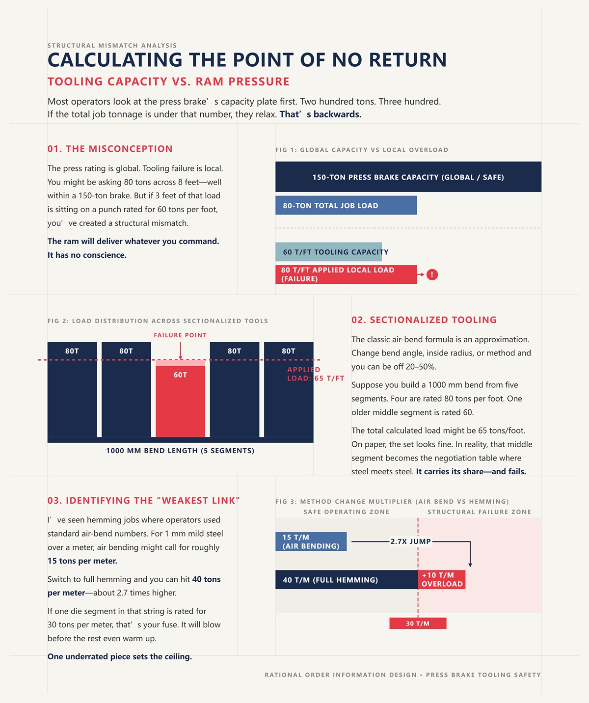
Most operators look at the press brake’s capacity plate first. Two hundred tons. Three hundred. If the total job tonnage is under that number, they relax.
That’s backwards.
The press rating is global. Tooling failure is local. You might be asking 80 tons across 8 feet—well within a 150-ton brake. But if 3 feet of that load is sitting on a punch rated for 60 tons per foot, you’ve created a structural mismatch. The ram will deliver whatever you command. It has no conscience.
The point of no return is where required tons per foot exceed the lowest-rated component in the stack: punch, die, holder, or clamp—not the machine frame alone. In practice, that’s why the brake and the tooling must be engineered as a unified system. A fully CNC-controlled platform, such as a CNC press brake solution from CN-HAWE, is designed to manage bending force, distribution, and repeatability across high-end sheet metal applications, helping ensure the commanded ram pressure stays aligned with real tooling capacity. Check your seat—because once the lowest-rated component is overloaded, the failure is already in motion.
Here’s where it gets slippery. The classic air-bend formula—force proportional to thickness squared times length divided by V-opening—is an approximation. Change bend angle, inside radius, or method and you can be off 20–50%.
Now layer in sectionalized tooling.
Suppose you build a 1000 mm bend from five segments. Four are rated 80 tons per foot. One older middle segment is rated 60. The total calculated load might be 65 tons per foot equivalent. On paper, the “set” looks fine. In reality, that middle segment becomes the negotiation table where steel meets steel. It carries its share—and sometimes more if alignment is imperfect.
The math doesn’t lie, but bad assumptions do. Always calculate tons per meter for the specific material and method, then compare it to each segment’s rating, not the average. Check your seat.
I’ve seen hemming jobs where operators used standard air-bend numbers. For 1 mm mild steel over a meter, air bending might call for roughly 15 tons per meter with tear-drop tooling. Switch to full hemming and you can hit 40 tons per meter—about 2.7 times higher.
If one die segment in that string is rated for 30 tons per meter, that’s your fuse. It will blow before the rest even warm up.
The weakest link isn’t always obvious. It can be a narrow die insert, a short punch segment, even the clamp system. One underrated piece sets the ceiling for the entire setup. The math doesn’t negotiate. Check your seat.
But what happens when the load isn’t evenly shared?
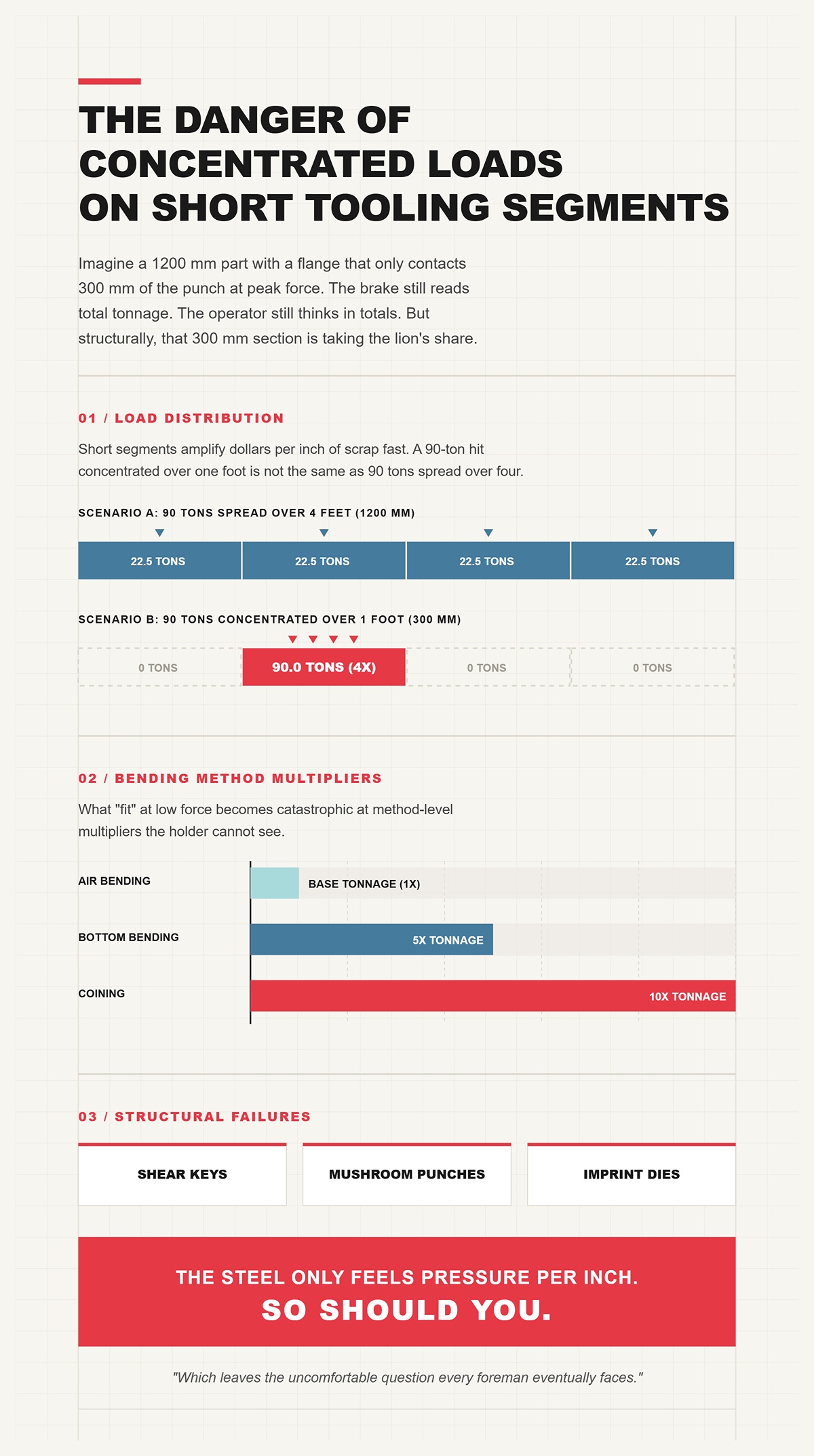
Imagine a 1200 mm part with a flange that only contacts 300 mm of the punch at peak force. The brake still reads total tonnage. The operator still thinks in totals. But structurally, that 300 mm section is taking the lion’s share.
Short segments amplify dollars per inch of scrap fast. A 90-ton hit concentrated over one foot is not the same as 90 tons spread over four. That’s how you shear keys, mushroom punches, and imprint dies.
Add bottom bending—five times the tonnage of air bending—or coining at ten times, and the margin evaporates. What “fit” at low force becomes catastrophic at method-level multipliers the holder cannot see.
The steel only feels pressure per inch. So should you.
Which leaves the uncomfortable question every foreman eventually faces.
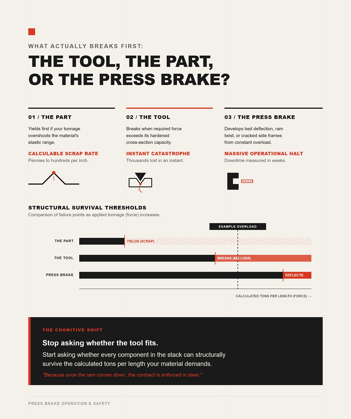
In most real shops, the press brake survives. It’s overbuilt, massively framed, and designed for full load cycles.
The part yields first if your tonnage overshoots the material’s elastic range. That’s scrap at a calculable rate—sometimes pennies per inch, sometimes hundreds if it’s aerospace alloy.
The tool breaks when required force exceeds its hardened cross-section capacity. That’s thousands in an instant.
And if you consistently overload, the brake develops bed deflection, ram twist, or cracked side frames. That’s when downtime starts measuring in weeks.
So the cognitive shift I want burned into you is this: stop asking whether the tool fits. Start asking whether every component in the stack can structurally survive the calculated tons per length your material demands.
Because once the ram comes down, the contract is enforced in steel.
I watched a young operator blue up a 4 mm plate once—layout dye across the bottom—then make a slow air bend and pull it out to read the witness marks on the die shoulders. The contact wasn’t centered. It was biting hard on one side, light on the other. That dye told the truth the tonnage display couldn’t: load wasn’t distributed the way the setup sheet assumed.
That’s your first practical control. Use layout dye or pressure film on the die shoulders, make a controlled hit at calculated tonnage, and inspect contact. If the witness is uneven, your tons per length are uneven, and some segment is negotiating harder than the rest. Shim, re-seat, re-check. The math doesn’t lie, but only if the geometry matches the math.
Now here’s where operators get casual. They treat the V-opening like a convenience—“What’s on the rack?”—instead of the primary lever that sets force. The standard air-bend formula scales roughly with thickness squared divided by V-opening. Double the V, you roughly halve the tonnage. Keep the V tight, and the load climbs fast. Yield strength sits inside that equation as a multiplier. Stronger steel demands more force for the same geometry. If you don’t widen the V to compensate, you push tons per foot toward the weakest segment in your string.
That’s how you verify and control distribution in practice:
The die opening is not about fit. It’s about structural survival under yield-driven load. Change the V, and you change the negotiation terms before the ram ever moves.
The job called for 78 tons per foot equivalent on 6 mm mild steel. Using the old 8× rule—V-opening about eight times material thickness—we picked a 48 mm die. Numbers checked out. Load per length sat just under the punch rating. Clean.
Then the material cert came in wrong. It wasn’t mild at roughly 60,000 PSI tensile. It was high-strength structural pushing 100,000 PSI. Same thickness. Same V. Required tonnage jumped by roughly the ratio of tensile strengths. You don’t need a whiteboard to see the problem. You’re no longer at 78. You’re north of 120 per foot.
The 8× rule works because it balances inside radius, tonnage, and material ductility for common low-carbon steels. But when yield strength climbs, that rule stops protecting you. Either you open the V—10×, even 12× thickness—or you accept a sharp rise in tons per length. And tons per length is what breaks tooling, not good intentions.
High-strength alloys are the exception that proves the rule: the V-opening must grow with strength if you want to keep structural load constant. Check your seat.
Stainless at similar thickness to mild will often demand about 1.4 to 1.6 times the force, depending on grade and condition. Aluminum 6061-T6 can surprise you too; despite being “soft” in conversation, its tensile strength in T6 temper sits high enough to demand real tonnage, and it cracks if you force too tight a radius.
I’ve seen operators keep the same 8× V from mild steel and just “push harder” on stainless. What actually happens is contact pressure on the die shoulders spikes, galling begins, and your localized tons per inch climb into tooling yield. Dollars per inch of scrap show up as surface tearing and micro-cracks at the bend line.
Open the V to 10× thickness for stainless as a starting point. For 6061-T6, consider both tonnage and minimum inside radius to avoid cracking; a slightly wider V reduces force and eases strain. You’re not chasing fit. You’re managing yield-driven load so the weakest segment never sees a surprise.
Now imagine you need a tighter inside radius than the 8× rule gives you. You drop from a 32 mm V to a 20 mm V on 4 mm steel to chase a sharper bend.
Force scales inversely with V. Reduce V by about 37%, and your tonnage climbs by roughly 60%. That’s not linear intuition—that’s the equation talking. If you were at 30 tons per meter, you’re suddenly near 48. Same material. Same length. Different die.
This is where shops get burned. They focus on the geometric outcome—“I need a sharper corner”—and forget that structural capacity is paying the bill. If that 48 tons per meter exceeds your lowest-rated die segment at 40, you’ve just engineered a failure point to win a radius.
Sharper bends cost in tonnage. The math doesn’t negotiate. Check your seat.
I once replaced a die set that looked fine dimensionally but had sharp, worn shoulders. Under load, stainless was dragging across those edges like sandpaper on aluminum.
A die shoulder radius controls how the sheet flows during bending. Too sharp, and contact area shrinks. Contact pressure—force divided by area—rises. That elevated pressure increases friction, which increases required bending force slightly beyond the clean formula. It also promotes galling, especially with stainless. Galling raises friction again. You get a feedback loop: more friction, more force, more localized tons per inch.
Widening the shoulder radius spreads contact, lowers peak pressure, and smooths material draw into the V. That doesn’t just protect surface finish; it stabilizes the load path so no small strip of die shoulder becomes the hidden failure point.
Inspect die shoulders with the same suspicion you inspect tonnage charts. A polished, properly radiused shoulder is part of your structural calculation, not cosmetic maintenance.
Here’s where method blindsides good math.
Air bending might call for 30 tons per meter on a given setup. Switch to bottoming—forcing the material fully into the die angle—and required force can jump to roughly five times air bending. Coining can reach ten times. Same V. Same thickness. Different method.
So if your air-bend calculation sat safely under a 40-ton-per-meter die rating, bottoming that same part could demand 150. The weakest segment doesn’t care that your opening width was “correct.” It only feels the multiplier.
Method choice is a structural decision. If you must bottom for angle control, you either increase V-opening, reduce bend length per hit, or split the operation into multiple bends to stay under per-segment limits. Otherwise, you’re signing a contract your tooling cannot honor. Check your seat.
Run two identical air bends: one on a clean, polished die; one on a die with embedded scale and light galling. Same programmed depth. Different angle result.
Why?
Friction between sheet and die shoulders resists material draw. Higher friction means the sheet doesn’t slide as freely into the V, which slightly alters the effective bending geometry and increases required force. That extra force shows up as more deflection in the brake and tooling stack, changing final angle through elastic recovery.
So you chase angle at the control, adding depth. That adds more force. Which adds more deflection. Which loads certain segments harder than the spreadsheet predicted.
Keep dies clean. Stone out galling. Verify angle against known-good material with documented tensile strength. Because bend angle accuracy isn’t just geometry and backgauge position—it’s a byproduct of force, friction, and elastic springback.
And that brings us to the next negotiation: once the V-opening and method set the force, how do punch radius and material memory decide where the angle finally lands after the load comes off?
We air‑bent 6 mm 304 stainless last winter. V-opening was correct. Tonnage per meter sat comfortably under the die’s rating. Ram depth hit the programmed value. Under load, the angle read 90° on the laser. We released pressure.
It opened to 94°.
Nothing “moved.” Nothing slipped. The machine didn’t lie. The steel simply relaxed. That four degrees is elastic recovery—springback—and it’s the part of the negotiation most operators treat like weather. But structural capacity isn’t a question of geometry; it’s a question of force per length. And once that force exceeds yield locally, the portion that did not plastically deform wants to come home.
The final angle after load release equals the plastic deformation you forced into the bend minus the elastic strain the material recovers. You don’t control that recovery with hope. You control it with punch geometry and process pressure. The math doesn’t lie. Check your seat.
In air bending, depth of penetration sets the loaded angle. A single punch can produce 70° or 130° depending on stroke. That’s true. But when we talk about springback control, we’re talking about what happens after the ram comes up.
Standard practice for a 90° finished angle in mild steel is an 85° to 88° punch. Why not a 90° punch? Because stronger materials spring back more. Stainless, high-strength low-alloy, 6061‑T6—they all store more elastic energy at the bend line. If you use a 90° punch and simply “drive deeper,” you increase force and deflection in the tooling stack, but you don’t change the plastic-to-elastic strain ratio at the apex in a meaningful way.
An acute punch increases localized strain at the bend apex for the same die opening and penetration depth. More of the material at the inside radius exceeds yield. Less remains elastic. Less elastic strain means less springback.
That’s not superstition. It’s strain distribution.
But how sharp is sharp enough before you just start crushing the surface?
I’ve seen a shop switch from a 90° punch to an 83° “compensation” punch on a job that was springing back about 7°. They expected magic. What they got was 3° improvement and a polished line on the inside radius.
Why? Because they stayed in air bending with the same V.
If you want to meaningfully reduce springback beyond a few degrees, you have to increase plastic flow at the apex. That means either narrowing the V-opening (raising tons per inch), or moving from air bending into bottoming or light coining where sustained high pressure forces the material into the die angle.
Bottoming can multiply required force by roughly five over air bending. Coining can reach ten times. That’s not a rounding error—that’s a structural decision. If your air bend ran at 30 tons per meter, bottoming may demand 150. Dollars per inch of scrap appear fast if your weakest die segment tops out at 120.
And here’s the catch: bottoming reduces springback not because the punch angle is magical, but because high localized pressure drives nearly full plastic deformation at the apex. You are buying angle stability with tonnage.
The contract is simple. More plastic strain now means less elastic recovery later. The math doesn’t lie. Check your seat.
But how do you know how much recovery to expect before you ever touch the pedal?
Take two 4 mm sheets: A36 mild steel and 100 ksi high-strength steel. Same V, same punch, same penetration depth to 90° under load.
Release them.
The mild might spring back 2°. The high-strength could open 5° or more. Why? Because yield strength defines how much stress the material can carry elastically before permanent deformation dominates. Higher yield means a larger elastic region in the bend cross-section.
Springback increases with:
That last one matters. A larger inside radius spreads strain across more material, lowering peak plastic strain at the apex. More of the cross-section stays elastic. More recovery.
Modern CNC brakes try to hide this from you with material libraries. You punch in “304 stainless, 6 mm,” and the control applies a compensation value. That only works if the actual sheet matches the assumed yield. I’ve seen heats of stainless vary enough to shift springback by a degree. On a four-bend part, that compounds. Two degrees per bend becomes eight degrees of accumulated error. That’s rework. That’s scrap. That’s dollars per inch of scrap stacked like poker chips.
Run a test bend. Measure unloaded angle. Adjust punch choice or programmed overbend accordingly. Treat the first hit as data collection, not production. Check your seat.
Now let’s kill a myth that costs shops money.
In air bending, the inside bend radius is primarily a function of die opening, not punch tip radius. A common rule of thumb: inside radius ≈ 16% of the V-opening for mild steel. So if you’re running a 40 mm V, you’re looking at roughly a 6–7 mm inside radius, regardless of whether your punch tip is R1 or R3.
I’ve watched buyers spec an R0.5 punch expecting a razor-sharp inside corner while leaving the V wide to keep tonnage down. They get the same broad radius, plus higher contact pressure at the apex. Surface marking goes up. Tool wear goes up. Angle consistency barely changes.
If you truly need a tighter inside radius, you narrow the V. But we already walked that road. Narrower V means higher tons per inch. A drop from 8× thickness to 6× can spike force dramatically. Structural negotiation again.
So punch tip radius matters most when you are bottoming or coining—when the material is forced to conform to the punch. In pure air bending, the die controls the radius, and the punch controls strain concentration and springback behavior.
Geometry is secondary to load path. Always has been.
Imagine a 1200 mm part with a flange that only contacts 300 mm of the punch at peak force. Now add a return bend that wraps back toward the punch body.
You select an acute punch to fight springback. It works on angle. But on the second bend, the formed flange crashes into the punch shank before you reach full penetration. So you swap to a gooseneck punch for clearance.
Here’s the paradox: the gooseneck gives you physical fit, but its longer, relieved profile can deflect more under load. More deflection changes actual penetration at the apex. That shifts the loaded angle. Which shifts the unloaded angle after springback.
On multi-bend parts, residual stress from the first bend changes the springback of the second. I’ve measured 4° compensation needed on the first bend and 4.5° on the second in the same material. Each bend rewrites the stress map. If you assume one compensation angle fits all, error multiplies down the line.
So with gooseneck geometry, you’re balancing three variables:
You don’t solve that at the control screen alone. You solve it with test pieces, angle measurement after release, and a cold look at tons per inch versus tool rating.
Tooling selection is a high-stakes negotiation between steel and steel. Tonnage is the currency. Springback is the fine print. Once the ram comes down, the contract is enforced in steel.
And even when the math is right and the geometry is right, there’s still one more way this deal can fall apart: alignment.
You did the math. Tons per inch are under the tool rating. Die width matches thickness. Springback is predicted, tested, compensated.
So how can the final angle still wander?
Because force doesn’t care about your spreadsheet. It flows where the steel actually touches. And if the ram, punch, and die aren’t seated in the same plane within a few hundredths of a millimeter, your clean 50-ton calculation becomes a lopsided spike on one shoulder while the other side loafs along at half load. The average is still 50. The local peak might be 70. That’s how you start digging shards out of your die.
We said springback control is a structural and force-distribution problem. Alignment is the part where that distribution either stays even—or turns into a knife edge.
The math doesn’t lie. But it assumes parallel seating.
And that assumption is expensive.
A press brake bed bends. Every one of them. Under load, the center wants to sag while the ends stay supported by the frame. If you don’t counteract that, the middle of your part sees less penetration than the edges, and your 90° target becomes 88° in the center and 91° at the ends.
Crowning is the correction—mechanical or hydraulic camber built into the bed to offset expected deflection under a given load. The keyword is expected.
Here’s where shops fool themselves: they dial in crowning based on total tonnage, not tonnage per inch and actual contact length. Imagine a 1200 mm part with a flange that only contacts 300 mm of the punch at peak force. Your display might show 60 tons total, but that force is concentrated in a quarter of the length. The bed deflects differently than your crowning curve assumes.
Now you’re not compensating. You’re guessing.
Hypothetical, but realistic: your tooling is rated for 80 tons per meter. You calculate 60. Safe, right? But if misalignment and uneven bed deflection shift 20% more load to one 300 mm region, that local segment sees the equivalent of 72 tons per meter. Add worn tooling needing a 20% safety margin, and you’ve quietly stepped beyond rating. That’s not a rounding error. That’s dollars per inch of scrap and a chipped shoulder waiting to happen.
The fix isn’t mystical. Verify ram-to-bed parallelism. Measure actual bend angle along the length on a test hit. Adjust crowning based on contact reality, not screen optimism.
Then check your seat.
Alignment errors rarely announce themselves with a bang. They creep in with a wrench.
Manual clamping systems rely on segmented bolts pulling the punch into the ram. If one bolt is torqued harder, that segment sits higher. We’re talking tolerances on the order of 0.05 mm across the bed. That’s thinner than a business card. Miss it, and one end of the punch makes contact first.
First contact takes first load. First load takes more strain.
Hydraulic clamping evens that pressure across the length, but it doesn’t cure dirty shoulders, burrs under the tang, or a chip trapped between punch and holder. Steel on steel does not forgive debris. One shaving under a segment becomes a fulcrum. Now your pristine tonnage calculation is riding on a pivot point you never planned for.
And here’s the cascade: uneven loading accelerates wear on that overloaded section. Worn tooling demands more penetration to reach the same loaded angle. More penetration means more tonnage. Alignment failure becomes a tonnage problem three weeks later, and nobody connects the dots.
You thought you were negotiating yield strength and die width. You were actually negotiating clamping discipline.
So before you trust the control’s angle correction, stone the shoulders. Clean the tangs. Torque evenly or verify hydraulic pressure. Indicate the punch if you have to.
Then check your seat.
Short answer: no.
If the next step is to speak with the team directly, Contact us fits naturally here.
For readers who want detailed materials, Brochures is a useful follow-up resource.
Long answer: premium tooling is ground straighter, harder, and more consistent than bargain steel. It distributes load beautifully—if the machine delivers that load evenly. But structural capacity isn’t a question of geometry; it’s a question of force per length. If the ram is out of parallel, the finest punch in the catalog becomes a pry bar.
Let’s say your ram is high on the left by 0.08 mm across two meters. That sounds trivial. Under load, that side contacts first and begins plastic deformation while the right side is still closing air. By the time the right engages fully, the left has already yielded deeper into the V. Release the ram and you don’t get uniform springback. You get a twist. One end springs back from a higher strain state than the other.
Angle error isn’t coming from material memory anymore. It’s coming from asymmetric strain history.
And premium tooling can’t rewrite that history.
I’ve seen shops chase this with overbend adjustments, adding a degree here, subtracting there, as if the control screen could iron out a mechanical tilt. All they did was drive the overloaded side closer to its structural limit. The math didn’t change. The distribution did.
So ask the unromantic question: when was the last time the ram parallelism was checked under load, not just at rest? A cold machine measures differently than one carrying 40 tons across the bed.
Because once the ram drops, the contract is enforced in steel—and steel only honors parallel seating.
Which is why the next step isn’t another calculation. It’s a disciplined loading and verification sequence that treats setup like the high-stakes operation it is.
The job called for 78 tons on paper. Eight-foot bend, 10‑gauge mild steel, one-inch V. The chart said 9.6 tons per foot. Do the multiplication and you’re flirting with the upper range of an 80‑ton tooling stack. On a 100‑ton brake, that feels safe. It isn’t.
Because we don’t run to nameplate. We cap working load at 80 percent. That 78-ton calculation just became a 62-ton planning number if you want process insurance for harder batches, worn shoulders, or a sheet that came off a different coil. Now the question isn’t “Can the machine do it?” It’s “Where will those 62 real tons sit, inch by inch, when steel meets steel?”
Here’s the sequence that keeps the first hit from becoming scrap:
That’s the protocol. Miss a step and you’re gambling dollars per inch of scrap.
And it starts with where you put the load.
I watched a crew set three stations across a 10‑foot bed: two light flanges on the left, one heavy channel form on the right. Total tonnage was within limits. Machine didn’t blink. But the heavy station carried nearly 60 percent of the load, parked 24 inches off center.
The machine frame doesn’t care about your floor plan. It cares about bending moment. When you offset tonnage, you introduce twist in the ram and asymmetric deflection in the bed. The control will still report total force. It won’t report that one side is living closer to yield than the other.
So we calculate a tonnage center—same way you’d find center of gravity. Multiply each station’s tonnage by its distance from machine centerline. Sum the moments. Divide by total tonnage. That gives you the load centroid. If it isn’t sitting on the machine’s structural center, you slide stations until it is.
Short parts tempt you to ignore this. Don’t.
Now layer in the 80 percent rule. Suppose your tooling is rated 80 tons per meter, and your heavy station needs 70 percent of that locally. You think you’re safe because total machine load is modest. But if that station sits off-center, dynamic deflection can spike local force beyond rating. The math doesn’t lie. Distribution rewrites survival.
On downstroke CNC brakes, the control corrects position in real time. That helps angle accuracy. It does not erase frame twist from a bad load map. Upstroke designs are even less forgiving because force application path differs; off-center loads show up as visible angular bias across stations.
Balance the tonnage center first. Then lock it in.
Check your seat.
I’ve pulled punches and found a chip no thicker than layout dye dried under the tang. That shaving cost a day’s production.
Seating isn’t cosmetic. It’s structural. A 0.03 mm burr under one segment becomes a pivot. Under 50 tons, that pivot concentrates load on the adjacent shoulder. Shoulder yields microscopically. Next run needs deeper penetration for the same angle. Tonnage creeps up. Nobody connects it back to a speck of steel.
Here’s the staging order:
Then bring the ram down to 2 mm above contact along the full length. Use a feeler gauge or a thin shim at multiple points. You’re looking for even daylight. If one side kisses first, stop. Correct now, not under load.
Because once you load it, mis-seating becomes strain history.
Check your seat.
Imagine a 1200 mm part with a flange that only contacts 300 mm of the punch at peak force. If that contact zone sits slightly left and the ram is 0.05 mm high on that side, the left edge yields first and deeper. Release the ram and the part springs back unevenly. You read 90° on the left, 91° on the right.
That isn’t springback variability. That’s asymmetric plastic strain.
To verify parallelism, make a light test hit across full intended contact length—just enough penetration to leave a witness line without fully forming. Measure gap between punch and die with shim stock at both ends. Alternatively, bend a calibration strip full length and measure angle at 100 mm intervals.
You’re hunting twist. Any consistent angle drift along the length means load isn’t landing square.
Correct with ram parallel adjustment and crowning tuned to actual contact length, not theoretical bed span. Only when angles match within your tolerance along the full length do you proceed to production depth.
The machine will not fix mechanical bias with software.
Check your seat.
Most operators look at one number: finished angle. That’s half the story.
On the first controlled bend, I watch three things:
If penetration is deeper than expected, ask why. Material yield may be higher than the chart assumed. Stainless is notorious for this; two batches labeled the same can demand noticeably different force. If you calculated 60 tons and the machine climbs toward 72 before hitting angle, your 20 percent reserve just vanished.
The math doesn’t lie, but your input might be wrong.
Now consider die width. A wider V lowers tonnage, yes. It also increases inside radius and minimum flange requirement. I’ve seen a shop open the V to save tonnage, hit angle perfectly, and then discover the flange geometry failed downstream fit. They protected structural capacity and sacrificed physical function.
This is the negotiation. Yield strength, die width, and tooling rating are arguing in the same room. The first test bend tells you who’s winning.
If tonnage is high and radius tight, consider stepping up V width and recalculating flange viability before committing. If tonnage is comfortable but angle drifts along length, revisit seating and tonnage center before touching the program.
One bend. Three diagnostics.
Program says 1.6 mm inside radius. That number came from a chart assuming a specific V opening—often about 16 percent of V width in air bending. But charts assume nominal yield.
After your first bend, cut and polish a sample or use radius gauges properly seated inside the bend. Compare actual radius to programmed expectation. If the true radius is larger, either the V is wide relative to thickness or the material yielded differently than assumed. Larger radius often means lower peak strain and slightly lower tonnage than predicted. Smaller radius in air bending usually means you’re closer to bottoming than you think—and bottoming multiplies force fast.
Force climbs roughly 1.5 times when transitioning from air bending to bottoming. That’s not a rounding error. That’s a tooling survival question.
So measure. Don’t assume the control’s model matches today’s steel.
When true radius, angle uniformity, and measured tonnage all align within your planned reserve, you’ve earned the right to run production.
Steel signed the contract.
Now ask yourself one thing before you hit cycle: if this load shifted two inches left, would anything in this stack be living beyond its rating?
If you can answer that without hesitation, you’re not just setting up a job. You’re managing structural risk on purpose.
Production is where the quiet failures start.
First ten parts look clean. Angle holds. Tonnage meter reads what you calculated. Then, three hours in, the machine needs 8 percent more penetration for the same angle. Nobody changed the program. Nobody touched the tooling. But something moved.
If you’re still asking “does this punch fit this holder,” you’ll chase ghosts. The real question, once production is running, is simpler and harder: is this stack still surviving the load I’m putting through it, exactly where it’s landing?
Because load shifts. Material yield drifts from batch to batch. Operators slide parts left or right to clear a backgauge finger. Crowning settings stay fixed while contact length changes. That’s how a 120-ton job quietly becomes 135 on one shoulder. The machine doesn’t complain. The die does.
The math doesn’t lie, but it only works if you keep measuring what the math assumed.
So the framework changes. Before cycle start, you asked whether the setup could survive the calculated force. During production, you ask whether the force is still landing where you planned—and whether the steel has rewritten the contract.
That’s the shift from fit to performance.
And performance fails first at the edges.
Shoulder sink is microscopic plastic deformation at the die shoulder under repeated high load. Tip compression is the same story at the punch nose. You won’t see either until accuracy starts drifting.
Here’s what I watch:
Each one is a load map drawn in steel.
Take a hypothetical: 10-foot tool, calculated 140 tons total. That’s 14 tons per foot average. But production reality puts 4 feet of actual contact slightly left of center. Now you’re closer to 35 tons per foot in that zone. If the die is rated 30 tons per foot, you’re burning 5 tons per foot into plastic strain every cycle.
Put that in shop language: if that die costs $1,200 and gives up 0.001 inch of permanent set every 200 cycles, you’re paying dollars per inch of scrap long before it cracks.
The monitoring method is simple and mechanical:
If tonnage climbs or penetration creeps, stop and recalculate tons per foot based on real contact length, not theoretical bed length. Then compare that to the lowest-rated component in the stack.
That’s how you catch overload before steel makes the decision for you.
Check your seat.
When angle drifts, the temptation is to “kiss” the die on the grinder.
I’ve seen more precision lost to grinders than to overload.
Grinding removes material uniformly. Shoulder sink does not happen uniformly. If the left 300 mm yielded 0.02 mm and you grind the full 3 meters to clean it up, you just shortened every segment. Now your shut height reference changes, your CNC depth numbers lie, and your crowning curve no longer matches reality.
Worse, you’ve reduced cross-sectional mass at the shoulder. Structural capacity isn’t just rating on paper; it’s section modulus—the geometry resisting bending. Remove steel, lose stiffness. Next run requires slightly deeper penetration. Tonnage creeps. You grind again.
That spiral is expensive in a way operators don’t see. Suppose each grind shortens tool life by 10 percent and you’re re-dressing quarterly. Over two years, you’ve thrown away half the structural margin you paid for. Dollars per inch of scrap turn into dollars per inch of tooling.
The fix isn’t cosmetic correction. It’s root-cause recalculation: was die width too narrow, material yield higher than assumed, bending method closer to bottoming than air bending?
Grinding hides math mistakes. It doesn’t solve them.
Check your seat.
Before any tool touches the ram, I run six questions. Not in my head. On paper.
If any answer is uncertain, I widen the V, change method, or split the bend into stages.
The one thing to carry forward is this: machine tonnage is global; failure is local. That’s not obvious until you’ve cracked a die in the middle of a perfectly “safe” 150-ton run.
A framework only matters if it survives a busy shift.
So I turn it into controls:
This isn’t bureaucracy. It’s structural accounting.
Imagine a 1200 mm part with a flange that only contacts 300 mm of the punch at peak force. If production starts alternating left and right loading to speed throughput, you’ve just created cyclic asymmetric strain in the tool stack. Over time, that’s how parallelism drifts even though your setup was perfect.
By logging tonnage and penetration together, you see that drift early. If penetration increases but tonnage doesn’t, material changed. If tonnage increases for same angle, contact length shrank or you’re edging toward bottoming. Each pattern tells a different story.
The math doesn’t lie. But only if you keep feeding it truth.
Over thirty years, I’ve learned this: precision CNC bending isn’t about finding a setting and walking away. It’s about running a controlled experiment every time the ram comes down, verifying that steel is behaving within the limits you negotiated.
Before cycle start, ask: can this survive the load?
During production, keep asking: is it still surviving it where I think it is?
That’s the lens. Not fit. Not nameplate tonnage.
Performance under real force.


