

A press brake isn’t a purchase—it’s a calculation. Yet too often that calculation is left to someone motivated by a quota, not by precision. When your tonnage numbers come from generic “standard charts” rather than the materials and parts you actually form, you risk ending up with a machine that either overpowers delicate work or grinds to a halt on profitable bends. The difference between accurate tonnage and guesswork isn’t theory—it’s the line between uptime and costly downtime.
You can’t judge bending force by eye—especially when tooling geometry, material properties, and workload mix can swing the required load by 30 to 70 percent. True sizing starts with physics, not pricing. That means uncovering how standard charts, tensile assumptions, and job variability distort your tonnage data—and learning how to replace loose estimates with solid calculations.
Every tonnage chart hanging in a showroom carries the same flaw: it assumes mild steel bent on flawless 8×S dies under ideal conditions. Actual production is never that tidy. Thin sheet bends more sharply; thick plate moves differently. Use too narrow a die (for instance, 6×S instead of 8×S) and your required force can skyrocket past the brake’s mechanical rating. Go too wide, and the ram must travel farther than the press can accommodate.
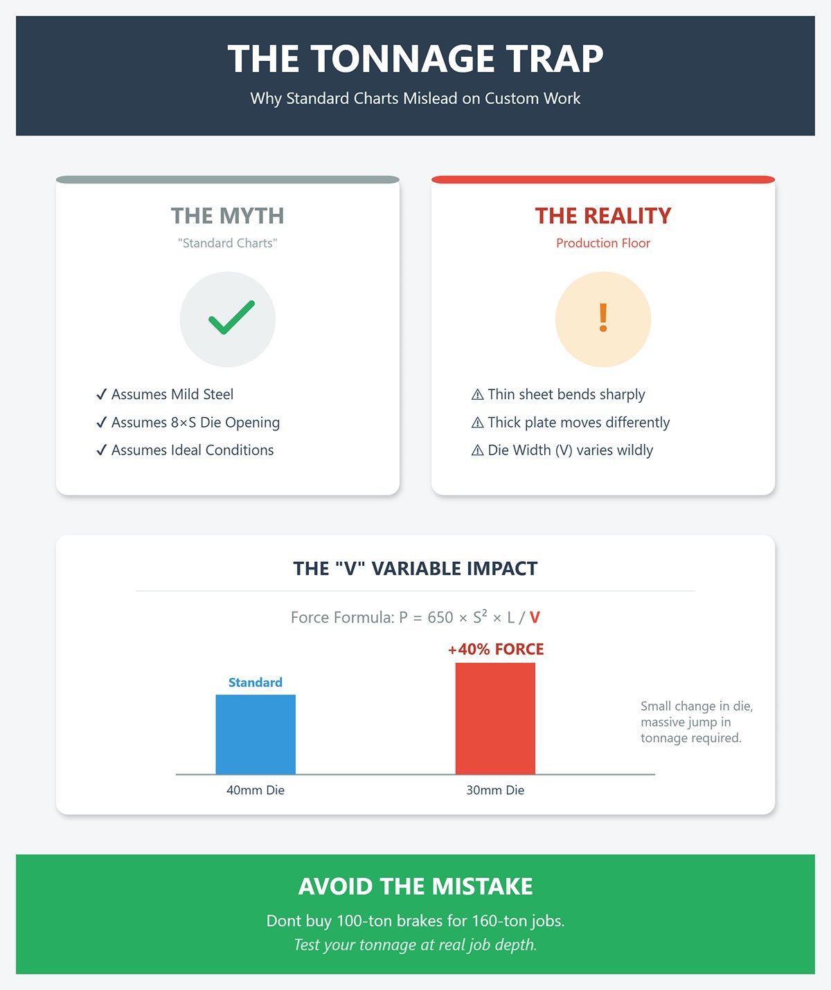
Here’s the real formula: P = 650 × S² × L / V, where P is in kilonewtons, S is thickness in millimeters, L is bend length in meters, and V is die opening. Divide by ten for tons. Adjust just one variable and your entire tonnage profile changes—particularly the die opening. Move from a 40mm to a 30mm die on a 5mm sheet and the tonnage requirement climbs nearly 40%. You rarely see this mentioned in brochures, because “standard charts” trade accuracy for simplicity.
The outcome is easy to predict: shops buy 100-ton brakes for parts that occasionally demand 160 tons, or overspend on oversized frames because a demo on thin stock looked perfect. Test your tonnage at real job depth, not showroom depth, and the numbers stop misleading you.
Stainless steel quickly exposes the folly of treating all metals as equals. While mild steel typically offers a tensile strength of around 450 MPa, stainless can push well beyond 700 MPa. That added resistance increases required tonnage by roughly 50%, yet many so-called “universal” tonnage charts still assume mild steel values. It’s why many buyers are caught off guard when their 100-ton press brake buckles under stainless parts they thought would bend with ease.
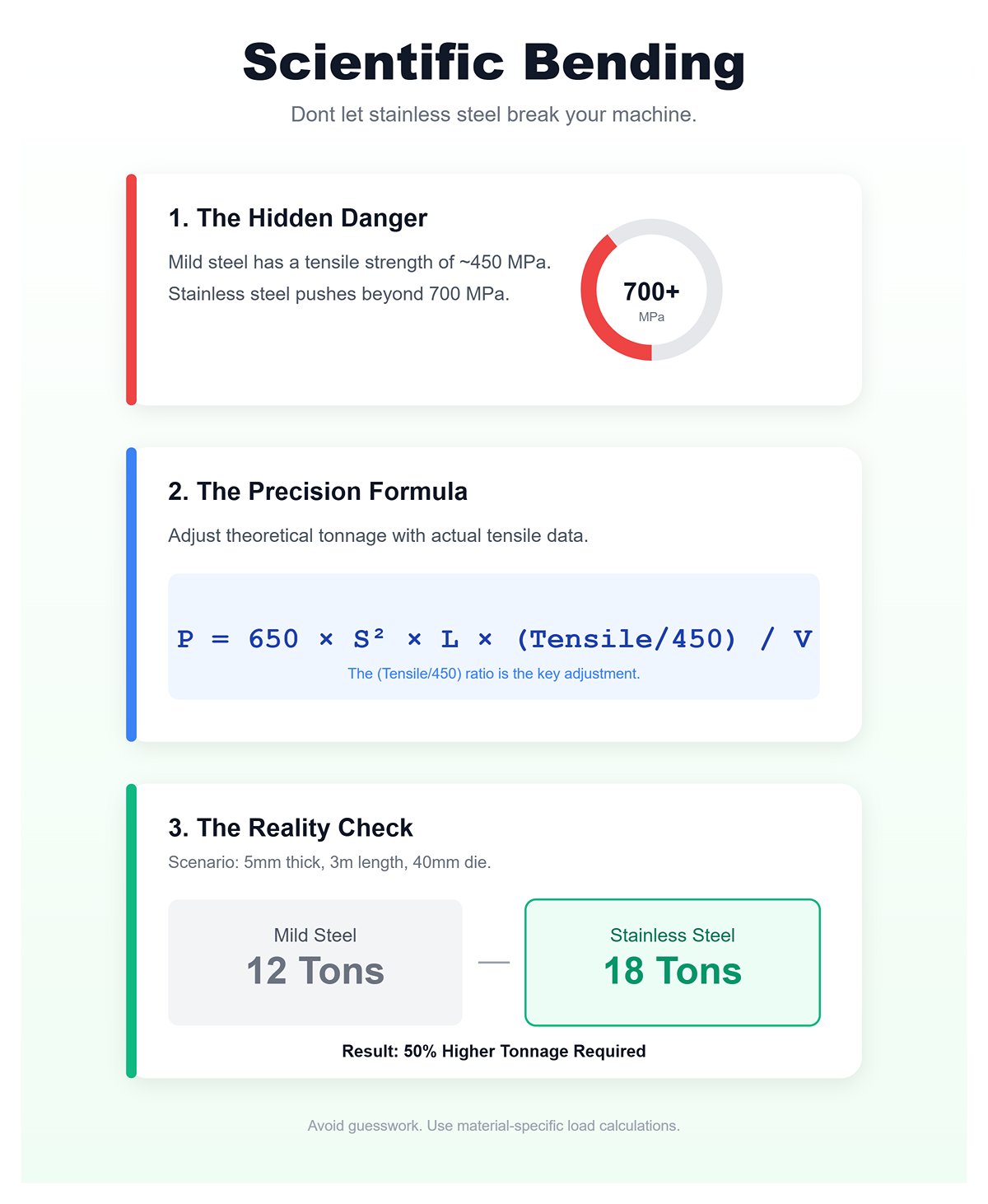
To correct for material strength, apply this modified baseline formula: P = 650 × S² × L × (actual tensile / 450) / V. This adjustment translates theoretical tonnage into real-world numbers. For 5mm stainless over 3 meters with V = 40mm, P ≈ 650 × 25 × 3 × 1.5 / 40 = 18 tons—compared to just 12 tons for mild steel. Scale that across an entire day’s run, and it becomes clear why undersized frames flex and yield inconsistent bend angles.
Charts that ignore tensile variations give a misleading picture of machine capacity. Modern tools—like Cincinnati’s Load Calc—use material-specific data rather than guesswork, calculating precise loads for each metal type. The solution isn’t buying the biggest brake you can find; it’s buying with scientific accuracy.
Few mistakes burn through capital faster than sizing a machine for a job you’ll almost never see. Many buyers spot a 10-foot sheet of mild steel at ¼” thickness and reach for a 165-ton press, forgetting that most of their production runs are half that length. When you design for typical workloads instead of exceptions, you reduce machine mass, power demand, and purchase cost—often saving $50,000 or more while maintaining full production capability.
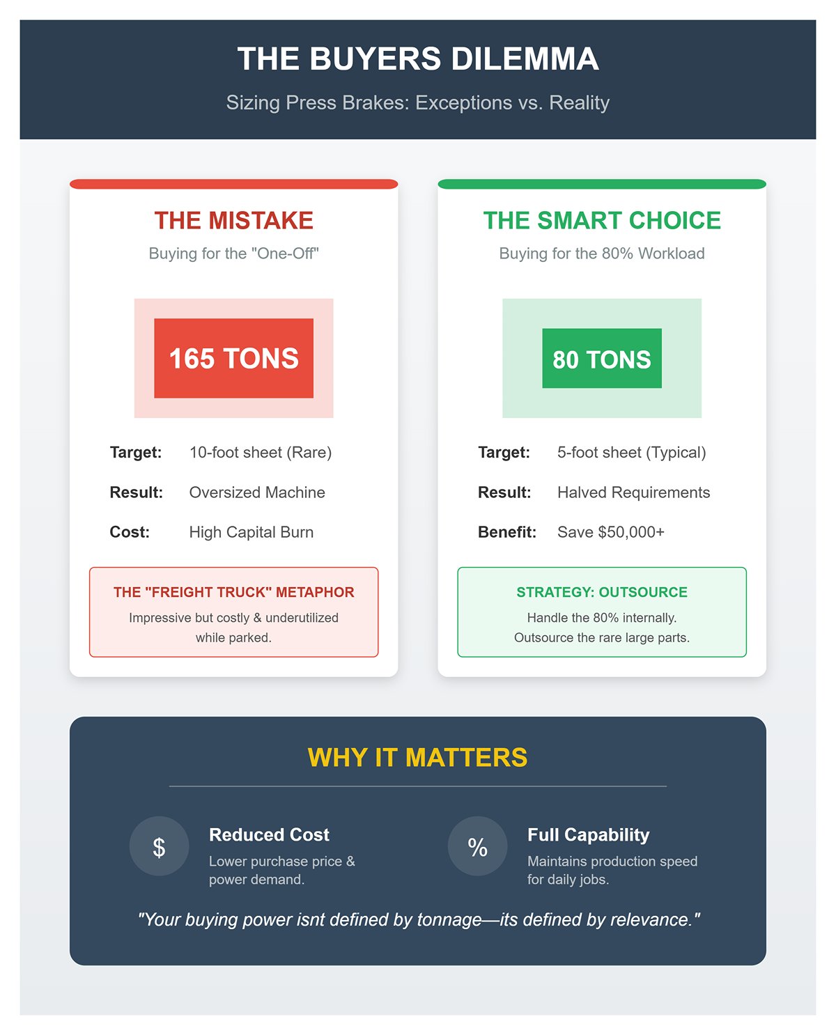
The smarter metric is this: rate your press for the 80% of parts you actually bend, and outsource the rare extremes. Halving working length nearly halves tonnage requirements—a 5‑foot workload runs easily on 80–100 tons, whereas a 10‑foot plate demands roughly 165. Remember, a press frame doesn’t provide free strength; it draws electricity and occupies space whether it’s working or idle. Oversized brakes are like parked freight trucks—impressive, costly, and underutilized.
Compare your specs to the jobs you routinely process. Use the Mild Steel Shortcut (≈8 × thickness(mm) × length(m) = tons), then adjust for stainless by a ×1.5–2.0 multiplier and include a 20% safety margin. That method will put you within about 10% of your real performance requirement—accurate enough to avoid both machine strain and unnecessary overspending.
Your buying power isn’t defined by tonnage—it’s defined by relevance. When you tailor a press brake to your everyday workload rather than rare jobs, the math rewards you shift after shift with consistent productivity and smart returns.
The stated bed length on a press brake rarely equals the true usable bending span. The key measurement is the distance between the machine’s side housings—those vertical frame members that support the ram and bed. This “column distance” often falls 10–20 inches short of the nominal bed length, especially in budget-oriented designs where frame width is minimized to save material. For instance, a brake marketed with a 120‑inch bed might provide only 104 inches of actual clearance. In such cases, a full-width panel will hit the housings unless positioned at an angle, introducing risks of inconsistent bends and possible tooling collisions.
Clearance for flanges adds another layer of complexity. Tall flanges can impact the ram or upper tooling during the return stroke if the vertical open height—the distance from bed to ram at full extension—minus the stroke length is less than the flange height. A common pitfall occurs when the open height is generous but stroke length is short, leaving inadequate space after forming. This can trap parts in the brake or force unsafe removal. To avoid this, don’t rely solely on bed dimensions; measure your tallest flange against the machine’s shut height, and add a safety margin for springback, which can demand 20–30% more clearance.
Throat depth—the horizontal distance from the bend line to the inside edge of the machine’s side frame—is frequently underestimated. Standard depths of 6 to 12 inches typically suffice for flat work, but can severely limit formed parts like U‑channels, deep boxes, or offset panels. If the distance from bend line to the far edge of the workpiece exceeds the throat depth, the material will strike the C‑frame during bending. This is especially problematic with large wraps or enclosure panels, which require significant swing clearance as the bend closes.
Thicker material further increases the demand for throat depth, as swing radius grows with gauge. Forming 1/4‑inch steel, for example, can require up to 50% more throat than light-gauge sheet to avoid frame interference. Many shops only discover this after cycle times balloon due to awkward part flipping or repositioning, which often introduces alignment errors. The simple preventative step: lay out your part drawing, measure from each bend line to the opposite edge, and ensure that distance fits within the throat depth plus a small clearance allowance.
| Concept | Description |
|---|---|
| Throat Depth Definition | Horizontal distance from the bend line to the inside edge of the machine’s side frame. |
| Standard Depth Range | Typically 6–12 inches; adequate for flat work. |
| Limitation for Formed Parts | Can restrict forming of U‑channels, deep boxes, offset panels if distance from bend line to far edge exceeds throat depth. |
| Potential Interference | Material can strike the C‑frame during bending, especially for large wraps or enclosure panels requiring swing clearance. |
| Effect of Material Thickness | Thicker material increases required throat depth due to larger swing radius. |
| Example Requirement | Forming 1/4‑inch steel may require up to 50% more throat depth than light‑gauge sheet to avoid frame interference. |
| Impact of Insufficient Depth | Leads to longer cycle times, awkward part flipping/repositioning, and alignment errors. |
| Preventative Measure | On part drawings, measure from each bend line to the opposite edge, and ensure it fits within available throat depth plus clearance allowance. |
A machine’s footprint involves far more than its bed length and frame width. Modern safety gear and service access zones introduce what’s often called the “ghost footprint”—the invisible buffer areas around the press brake that must stay clear. Light curtains, required by OSHA for certain operations, typically need at least 20 inches of spacing from the tooling line to the emitter and receiver posts. Swing‑away backgauges can extend even farther during tool change cycles, tracing arcs between 18 and 24 inches. Electrical cabinets frequently add another 12–16 inches to the back or side dimension.
When you factor in all these components, a press brake with a nominal 10‑foot bed may actually demand more than 14 feet of usable floor space. Overlooking these extra zones can choke workflow, obstruct forklift aisles, or breach required safety setbacks. Some presses even experience slight frame deflection during heavy loads—certain European models have documented 2–4 inches of throat movement under high tonnage—which can subtly alter clearance zones mid-cycle. Always plan using live operating measurements rather than static catalog specs.
You can conduct a quick clearance audit in just a few minutes using the parts you already produce:
Success means verifying that every critical measurement of your parts fits comfortably within the machine’s true working envelope, not merely its bed length. If even one part doesn’t pass these clearance checks, that’s a warning sign. Adjust the machine specification or modify the part geometry before committing to a purchase. This five‑minute assessment can save thousands in setup time and prevent costly after‑delivery modifications.
The belief that adding more axes automatically boosts profits is one of manufacturing’s enduring misconceptions. In truth, every control upgrade compounds complexity faster than it expands capability—unless your workflow and operators are ready to leverage it fully. A sophisticated 6‑axis CNC press brake only delivers ROI when operators can interpret complex bend data, compensate for springback, and handle live angle corrections. Without those skills, the added precision stays locked inside the software while labor costs and machine depreciation rise.
For the majority of job shops, synchronized Y1/Y2 axes handle about 80% of bending operations with sub‑millimeter precision. A Level II operator certified under NIMS standards can consistently achieve ±0.5 mm accuracy on straight flanges using semi‑automated NC controls. That same operator costs less to hire and train than maintaining software licenses and ongoing instruction for a multi‑axis CNC. When well‑trained technicians outperform under‑utilized automation, the payback period on extra hardware simply disappears.
Fabrication audit data confirms this trend: shops running 4‑axis NC systems with experienced operators produce parts indistinguishable in quality from those made on 6‑axis machines—except for deep‑box or complex multi‑bend work. The hidden cost is not the extra servo, but the specialist required to keep it calibrated. Unless you’re producing high‑precision aerospace or appliance panels daily, the cost‑benefit equation consistently favors hiring skill over buying capability.
Offline programming separates theoretical efficiency from real throughput. A true CNC press brake justifies its investment when the next job is staged while the current one is still cycling. The key indicator is straightforward: can your operator load tooling data and simulate Job #2 within ten minutes of Job #1’s run start? If not, a portion of your CNC’s value is idling in queue time.
Shops with high‑mix, low‑volume production often underestimate how much overlap potential they’re leaving untapped. On manual or NC brakes, operators must stop production to reset gauges, realign dies, and trial the first piece. That 25–40% downtime quietly eats into capacity. In contrast, a skilled CNC operator using offline programming can validate collision paths and adjust tooling before the brake finishes its last cycle—pushing spindle utilization closer to true continuous operation.
The hidden challenge is that possessing offline capability on its own solves nothing. It requires solid proficiency in reading blueprints, calculating bend deductions, and navigating machine coordinate systems. New hires frequently falter here—misreading bend allowance charts or neglecting to confirm back‑gauge coordinates during simulation. When that occurs, offline programming tools become little more than expensive digital paperweights. The guiding principle is simple: if your fabricators cannot independently interpret a control sheet, focus on comprehensive training before sinking money into upgraded controllers.
Crowning compensation—the intentional upward curvature in a press brake bed or ram to counteract deflection—is an exacting test of both geometric knowledge and patience. With manual crowning, operators must understand how load, material thickness, and workpiece length combine to warp a beam. If the calculations are off, the resulting bend is off—and even a ten‑degree error across one meter of stainless steel can render an entire high‑value batch unusable.
Hydraulic or CNC‑driven crowning removes the guesswork. These systems measure ram deflection under load and adjust the central support automatically, ensuring flatness without operator input. Manual methods, on the other hand, lean on shim packs or hand‑wheel screws—solutions that work well for seasoned operators but can be unforgiving for novices. Fatigue also plays a role; after hours of physical shimming, precision can slip by several degrees, triggering rework cycles that cut deep into profit margins.
For production managers, this is the point at which alarm bells should ring. If your team routinely struggles with blueprint interpretation and the trigonometry required for accurate compensation, the real cost of manual crowning extends far beyond longer setups—it escalates into costly material waste. Your breakeven strategy comes down to two paths: committing six to twelve months to intensive operator training, or investing in a CNC system that automates the process entirely. One route preserves labor value; the other safeguards against fundamental physics you can’t override manually.
Press brake tooling isn’t universally compatible, and assuming it is can quickly turn your brand-new machine into an expensive piece of idle equipment. Traditional American-style tooling, common in older U.S. facilities, features a flat tang with inch-based mounting dimensions. European-style tooling, by contrast, typically has a narrower tang, precision-ground shoulders, and follows metric standards for die openings. These two systems are fundamentally different and cannot be swapped interchangeably without modification.
The incompatibility issue is serious enough that industry surveys link 30–50% of installation delays directly to mismatched tooling orders. Consider the case of a shop that purchased a high-end European press brake fitted with metric-spec clamps, but then tried to save money by ordering an American-style punch set. The result? The punches wouldn’t fit, forcing three costly choices: machining custom shims to bridge the gap (costing over $5,000), buying a dedicated adapter system with added complexity, or replacing the tooling altogether. Each option meant weeks of lost production and a tooling budget that ballooned to more than four times its original estimate.
The fix is straightforward but absolutely critical: confirm your machine’s clamping system, tang profile, and die seat dimensions before ordering any tooling. Match not just the overall style—American or European—but also the specific manufacturer’s tolerances for height, width, and load ratings. This diligence eliminates the risk of retrofits, budget overruns, and missed delivery deadlines that can sabotage your press brake’s return on investment before you’ve even made your first part.
Ordering an all-inclusive tooling set—with every conceivable punch and die—might sound appealing, but it’s almost always a waste of resources. In practice, most shops can handle 80% of their work with just three carefully selected tools: an acute punch (85°) for versatile angle bending, a gooseneck punch for boxes and channels, and a matched-radius die sized for the thickest sheet you regularly process (die opening guideline: 8× material thickness).
Before the machine is installed, analyze your past quarter’s jobs using a tooling map. Pinpoint the profiles you form most frequently, the materials in use, and the angles required. Start with this lean “Day One” kit, then monitor actual setup times and defect rates in production. If a specialized tool—such as a $1,375 louver punch—remains unused across multiple runs, it’s not an investment; it’s simply tying up capital.
This phased purchasing strategy shifts tooling acquisitions from speculative spending to investments backed by real-world proof. One fabrication shop used post-installation audit sheets to identify and cancel orders for 40% of tools initially thought essential—but never actually used. The savings were funneled into high-speed clamping systems, cutting setup times in half for each job and boosting throughput well beyond what their original all-inclusive tooling package could deliver.
Budget dies from unverified suppliers often claim “comparable” bending capacity but fall short in metallurgy and dimensional accuracy. One frequent problem shows up when working with stainless steel, which has a higher K-factor—meaning more springback—and needs about twice the forming pressure of mild steel. Low-grade dies frequently crack or chip under these forces, particularly along the shoulders, and lose precision at the V-opening, leading to premature replacement.
Over a two-year period, the cost math is harsh. An $800 die set replaced twice a year racks up $3,200 in purchase costs. Factor in lost productivity—five minutes per part at $30/hour labor—and you’re over $7,000 in downtime for each replacement, not even counting waste from misaligned bends. In a mid-volume shop, the hidden tab can easily hit $50,000 before anyone notices the replacement cycle’s real impact.
In contrast, premium dies with precision-ground V-openings and heat-treated alloys routinely last 18–24 months under mixed workloads, holding bend accuracy and cutting scrap rates by as much as 40%. One medical device manufacturer documented a 55% reduction in rejects after upgrading to top-tier tooling—recovering their full investment in just 16 months, while reclaiming hundreds of labor hours previously lost to defect troubleshooting.
The bottom line: tooling costs aren’t optional, and underestimating them often results in a nasty “$10,000–plus” surprise for buyers. Even a basic, all-purpose set for a small press brake can run $1,000–$5,000. More advanced configurations—especially those for multi-axis CNC brakes with Y1/Y2/R control, crowning systems, or automated tool changers—can easily reach $10,000–$20,000, with CNC changer integration adding another $5,000–$30,000.
Before investing in tooling for projects that may never materialize, confirm your real bending requirements. Optimize your typical part layouts to achieve at least 85% sheet utilization, run simulated bending programs, and verify that the bending profiles align with your anticipated production mix. This pre-tooling review helps identify “unicorn” jobs—specialized profiles dreamed up during the machine’s planning stage but never actually needed.
Allocating budget for tooling ahead of the brake’s arrival shifts your purchase mindset from machine-centric to production-centric, ensuring you can achieve maximum efficiency from day one. The true worth of the machine isn’t in its tonnage rating or brand reputation—it’s in the precision, adaptability, and uptime that the right tooling unlocks.
A press brake’s frame holds the history of every sheet it has bent, and checking ram parallelism is one of the quickest ways to read that history. Use a precision straightedge or dial gauge across the ram at several points, cycling it through its full movement. If deviation exceeds 0.001 inches per foot, chances are the frame has been distorted by repeated overloading—common when operators exceed tonnage limits on thick stainless steel or high-tensile materials.
For a quick assessment, perform the test twice: once with no load, and again at around half the machine’s rated tonnage. In a well-maintained hydraulic brake with independent Y1 and Y2 rams, both sides should stay within 0.002 inches of each other. If not, it likely means the brake has been run beyond its design capacity, sacrificing bending precision. Ignoring this check can lead to costly realignment work—some shops have paid thousands to fix frame issues missed at purchase. A reputable seller should welcome a parallelism test; if they refuse, consider walking away or insist on a significant discount to cover rebuilding costs.
While a press brake’s mechanical components can last decades, its electronics often fail much sooner. Pre-2000 NC systems and early CNC controllers from brands like Delem or Cybelec may still operate the ram smoothly, but once the manufacturer ends firmware and parts support, a failed servo or communication module can render the entire machine useless. In some cases—such as outdated TP10S-style panels—replacement parts are unobtainable, leaving a full control retrofit as the only option, typically costing $10,000–$15,000.
Even controllers that seem relatively modern can turn into “orphans” if they rely on proprietary software ecosystems or don’t allow offline programming. Before committing to a purchase, upload a simple test program that includes basic bends and an R-axis (backgauge) movement. If it can’t run the routine without errors or crashes, the electronics will almost certainly falter during production. Strong mechanics won’t compensate for unreliable control. A stable, well-supported interface is every bit as critical as a solid frame—without it, downtime will quickly wipe out any savings from buying secondhand.
Hydraulic leaks are inevitable over a press brake’s lifetime—but their severity varies widely. A light film of oil on the ram at full extension usually indicates rod seal wear, which is a low-cost fix, typically $50 to $200 per side for quality parts. However, if you hear whining under load, see fluctuating pressure readings, or notice foamy oil in the reservoir, you may be facing pump trouble. Replacing a failed variable-displacement pump often costs between $5,000 and $8,000, not counting the lost production time.
To tell the difference between a minor leak and real pump damage, cycle the ram with no load at about 80% of maximum speed. If the ram drifts after stopping or the pressure fluctuates under steady conditions, suspect a pump or valve issue rather than bad seals. Inspect the oil as well: dark fluid with metal particles might indicate contamination that’s been mistaken for pump failure. In many cases, a $300 system flush can restore proper function, provided the system meets cleanliness standards. Always test with the hydraulic fluid at operating temperature—around 140°F—since cold oil can disguise leaks while heat reveals how the components perform under actual stress.
A smart buyer arrives at the inspection prepared with three fast tests: a parallelism check, a controller program load, and a hydraulic cycle. In less than an hour, you can confirm frame precision, ensure the electronics are stable and supported, and accurately factor any hydraulic issues into your offer. If the ram remains true, the controller runs a basic job without errors, and the hydraulics maintain pressure smoothly, you’ve likely found a good machine. But if any of these fail—especially the control system—you’re looking at a costly mistake. These quick checks don’t just identify flaws; they tell you, right then and there, whether you’re about to purchase a productive asset or a costly headache dressed in fresh paint.
A professional press brake quote should resemble a custom-fit suit—not a bloated invoice full of extras you never requested. Begin by clearly defining the materials, thicknesses, and bend lengths that make up 80% of your jobs. These are your essentials; anything beyond them stays optional until proven necessary. For example, if your regular work involves bending 3/16-inch 304 stainless over a 96-inch span, make the vendor demonstrate the machine’s tonnage capacity, bend precision, and tooling compatibility at that exact workload.
Replace vague claims like “handles up to X tons” with precise calculations: require the vendor to specify tonnage based on your actual V-die width, material tensile strength (typically above 80 ksi for stainless), and bend length. This eliminates inflated size recommendations designed to inflate prices and waste valuable floor space.
Tooling mismatches often drain budgets quietly—especially when American and European/Wila systems don’t align. The wrong combination can cripple setup efficiency and saddle you with costly adapters. Require the supplier to confirm compatibility with your installed tooling style, punch height, and die width. And insist on a complete “Day One kit” that covers core applications—straight 90° bends and hems—so production doesn’t stall while you wait for missing components.
Specifications may sell machines, but demos reveal the truth. Always require your actual parts, materials, and bend sequences to be tested on the candidate press brake—live or on video. Treat it as mandatory: “Form my 8-foot, 10-gauge steel component with 90° flanges, record all dimension readings before and after, and capture the back gauge in operation through every cycle.”
Buyers who take this approach uncover nearly every flaw the spec sheet hides—ram repeatability problems, back gauge drift, and tooling seat play. A seemingly minor 0.015-inch variance becomes serious when scaled across an entire production run, pushing every flange out of tolerance and demanding costly rework.
Go beyond a single test bend—run a realistic production sequence: multi-step boxes, hems, or offsets. This will uncover throat depth constraints, collision points, and software slowdowns during complex, multi-axis cycles. It’s also the stage to evaluate offline programming: measure how long setup takes and whether the system identifies potential U-bend collisions or relies on endless trial adjustments.
A machine that looks ideal in the brochure but arrives four months late will cost more long-term than paying a bit extra upfront. Missed delivery deadlines can drain mid-sized shops of thousands each week in lost output. Your RFQ should spell out firm delivery dates, enforceable penalties for delays, and precise terms for after-sales support.
Put it in black and white: “Ship by the stated date or incur a 1% penalty for each week overdue; confirm the port of entry; define who manages customs clearance.” Demand written commitments for training hours, maximum field technician response time (no more than 48 hours), and guaranteed availability of spare parts in your country for at least two years. Phrases like “TBD” or “subject to availability” often mask slow service or missing components.
Confirm the exact installation footprint before you sign off. CAD drawings must reflect all clearance needs—back gauge travel, safety curtain swing, electrical cabinet projection, plus operator space on every side. Overlooked inches can block forklift access or squeeze your workflow, turning a supposed deal into an operational headache.
Your RFQ should finish with the one question that demands total transparency: “What’s your lemon rate?” If they track how many machines are returned or replaced, they’ll give a figure. If they side-step, assume you’re next on their problem list. Back this up with data—uptime percentages at six and twelve months, tooling failure records, and warranty claim history for the exact model you’re being quoted on.
Consider this example: a Midwest fabricator requested quotes for three similarly sized machines. Test runs uncovered hidden issues—parallelism drift on full-length heavy plate, back gauge stalls on hems, and controller lag during offline programming. The two cheaper options would have led to $20,000 a year in lost productivity. The vendor that met every RFQ specification delivered 99.8% repeatability and shipped exactly on schedule.
Once you submit an RFQ like this, the divide becomes clear—poor suppliers fade away, strong ones engage. You’ll stop buying press brakes on blind trust, because the evidence will be right in front of you.


