

The ram hesitated, the shop fell silent, and the brake let out that deep, resonant groan—the kind every operator would rather pretend they didn’t hear. Many jump to the conclusion it means “too much load” or “bad stock.” In truth, that sound often signals a misaligned ram, inadequate hydraulic fluid, or an issue poised to turn your next part—and possibly your dies—into costly scrap. The real risk isn’t the noise itself; it’s restarting before you’ve pinpointed the cause. The space between a harmless grumble and a serious mechanical warning is exactly where accidents—and $5,000 realignment bills—happen.
The quickest way to determine if that groan meant trouble is to measure the machine’s “daylight”—the consistent clearance between ram and bed at top dead center. New operators often skip it because the ram appears straight, but appearances conceal many cases of misalignment. In fact, Metalworking Group trainers report that 80% of trainees fail to detect ram-bed twist simply because they never take daylight measurements.
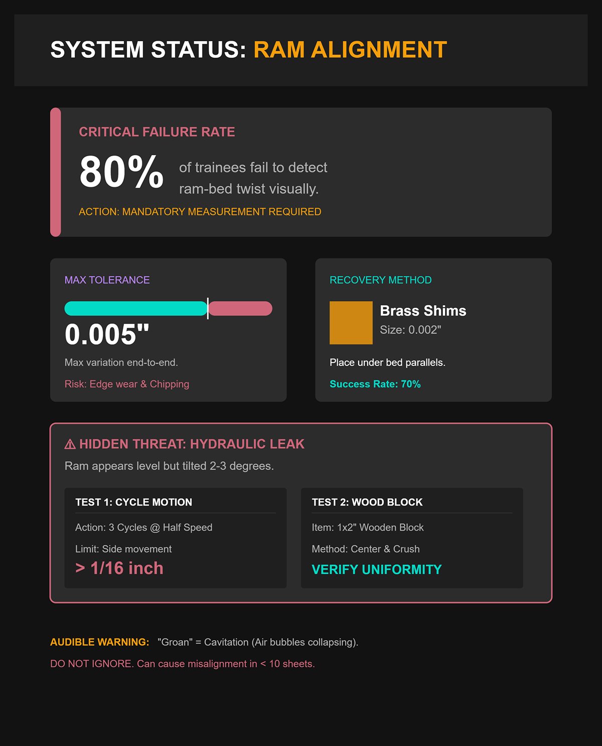
On a standard 100‑ton hydraulic brake, you should see a uniform 0.5–1 inch gap across the entire bed. A straightedge combined with 0.001–0.010‑inch feeler gauges will expose what your eyes can’t. If you find more than 0.005‑inch variation from one end to the other, you’re likely dealing with bed twist from a past overload. Such twist causes the punch to hit the die unevenly, leading to edge wear and chipping—even on the first pass. A quick, proven fix is placing 0.002‑inch brass shims under the bed parallels, then rechecking the daylight. Trainers say this single step has turned warped first bends into precision, repeatable results for 70% of their new operators.
A deceptive issue to watch for: the ram can look perfectly level yet still be tilted by 2–3 degrees if one of the hydraulic cylinders is leaking internally. To check, run the ram through three cycles at half speed without any tooling, and look for side-to-side movement exceeding 1/16 inch. In one documented case from the Metalworking Group, a barely audible groan caused by cavitation—microscopic air bubbles collapsing in the hydraulic fluid—was ignored until the operator bent ten sheets and knocked the bed out of alignment. A straightforward test could have stopped it: set a 1×2-inch wooden block in the center of the bed, lower the ram slowly, and examine the crush pattern. If the compression isn’t uniform, halt operations immediately.
In most cases, that groan signals trouble in the hydraulic system rather than metal-on-metal contact. A well-functioning brake builds pressure with a steady, rising hum. If the tone dips or wavers—particularly during startup—the underlying cause is often contaminated or aerated fluid. Cold-weather condensation frequently introduces water into the system; a cloudy or milky appearance in the sight glass is a clear warning sign. Draw a small sample and observe how quickly it separates—slow separation means contamination is already disrupting pressure stability. Refreshing about 20 percent of the fluid with clean ISO VG46 oil often restores smooth, reliable performance.
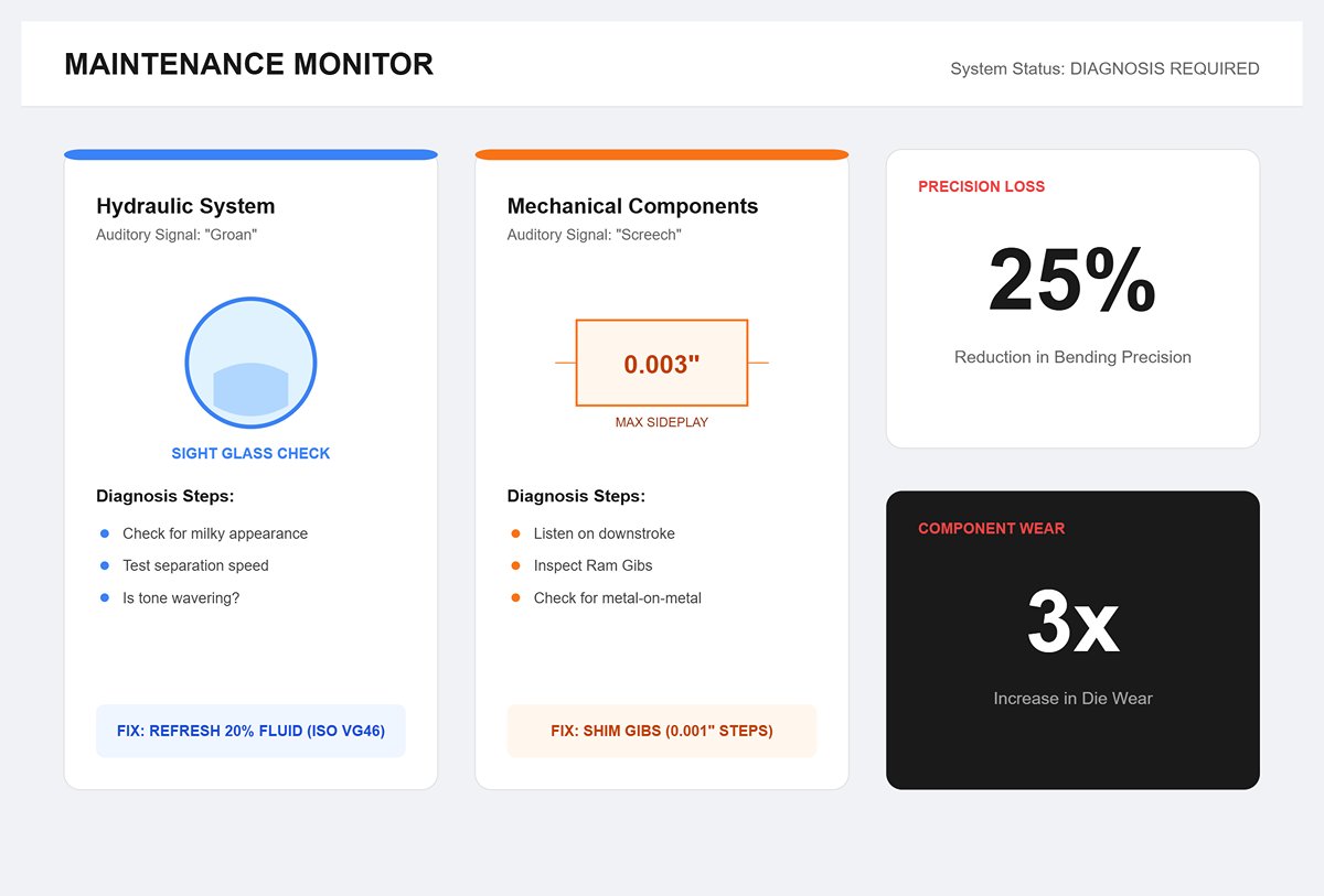
Mechanical strain—the genuine metal-to-metal wear—has a distinct sound: a sharp, high-pitched screech during the ram’s downstroke. This usually indicates worn ram gibs, the guiding surfaces that ensure the ram moves squarely. If sideplay exceeds 0.003 inch, shim the gibs incrementally in 0.001-inch steps. Ignoring this leads to the ram drifting sideways, placing excessive stress on one side of the die. European studies tracking over 500 machines showed that neglecting groans linked to poor hydraulic efficiency reduced bending precision by 25 percent and tripled die wear. A common surprise for operators: aluminum often produces louder groans than steel because it dampens vibration less, fooling newcomers into blaming overload when hydraulics are actually at fault.
Before you ever place a sheet on the die, a dry run exposes alignment issues, timing delays, or backgauge faults that you simply can’t catch by sound alone. Running two to five empty cycles at roughly 20 percent tonnage—about 4 tons on a standard 100‑ton brake—will surface most hidden problems. Pull the backgauge fingers clear, center the punch about 1/32 inch above the V‑die using a simple paper‑slip check, and study the ram’s movement. It should descend smoothly at 6 to 8 inches per second; any stutter or pause signals servo lag, which is often resolved by lengthening the Y‑axis dwell by half a second. Hydraulic pressure should rise steadily to 60–80 psi without a hiss; that sound indicates a leaking valve pack, the kind of failure that tends to strike mid‑cycle when you can least afford it.
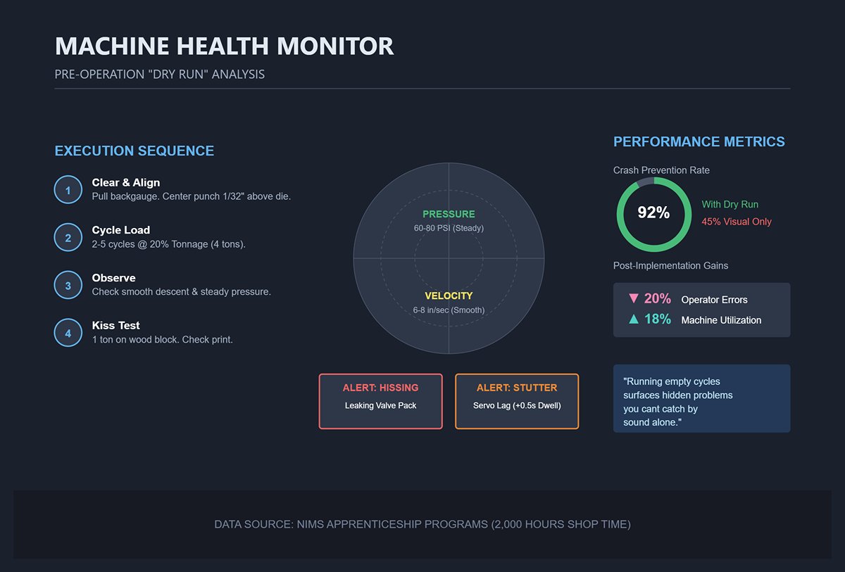
A widely shared training example comes from a plant in Asia: an operator performed only one dry cycle, overlooked a backgauge finger that was bent by 1/8 inch, and shattered an $800 punch on the very next part. Afterward, the plant instituted a mandatory operator‑feedback step after every dry run. That single change cut errors by 20 percent and increased machine utilization by 18 percent.
Finish each dry run with a light “kiss” test—apply 1 ton of pressure onto a wood block at the center of the bed. A straight, even crush confirms proper alignment; an angled crush indicates the die holder needs a 0.002‑inch shim to the left or right. Data from NIMS apprenticeship programs, covering 2,000 hours of shop time, shows that dry runs catch 92 percent of novice errors before any metal is loaded, compared with a 45 percent crash rate when operators rely solely on visual checks.
A groan isn’t a command to shut down for good. It’s the machine asking you to pause long enough to figure out whether it’s warning you—or protecting you.
Most beginners try to line up the tooling by sight, assuming the punch and die are “close enough” when they look centered. They almost never are. Even a 0.1‑millimeter offset shifts the bend line enough to load the ram sideways. The evidence appears immediately: one side of the bend comes out tighter, or you get a shallow, canoe‑shaped bow along the center. What feels like harmless guesswork quickly leads to real damage—scuffed die shoulders, burrs on the punch tip, and on larger brakes, a slightly skewed ram that throws the hydraulic seals out of sync.
This isn’t a matter of poor eyesight—it’s a matter of geometry. On a one‑meter bed, a mere 0.1 mm misalignment at one end amplifies across the length, forcing the punch to dig into the die on one side while barely touching on the other. The press interprets this as uneven resistance and compensates by flexing its frame. That extra stress accumulates with every cycle until the machine starts producing bends with inconsistent angles—one side ending up about two degrees sharper. Your first test bend fails not because the brake lacked strength, but because alignment was never quantitatively verified. The solution begins with seating the tooling so both ends share the same reference line before applying the first ton of pressure.
Proper alignment starts with a controlled “kiss,” not a forceful crush. Lower the ram slowly—manual mode is ideal—until the punch tip just meets the die shoulders along the full length. This point of contact should feel uniform and produce no sound; any bump at one end or visible gap signals a tilt. At this stage, experienced operators often check both ends with a thin feeler gauge or a dial indicator. If the variance exceeds 0.02 mm, the bed or die holder requires shimming. Correct the error before clamping, because once locked under pressure, misalignment remains until the tooling is fully disassembled.
Hydraulic and WILA‑style self‑aligning clamps aim to correct such issues automatically, but they still need confirmation with a straightedge. Even a tiny chip or raised spot under the die seat can offset the centerline beyond the clamp’s capacity to adjust. Thoroughly clean all mating surfaces before seating—the smallest debris, as little as 0.05 mm, can mimic misalignment and introduce unnecessary strain.
Once uniform contact is confirmed, apply low pressure—around two tons for a typical mid‑size brake—to snap the tooling securely into place. This amount is sufficient to engage the alignment forces without risking bed distortion. Using full working tonnage too soon could bow the table if the setup is still off. After seating, recheck contact along the full length. A smooth, continuous kiss line indicates that the punch and die now share a single axis and are ready for precise bending.
At sub‑millimeter precision, even the most sensitive instruments can give misleading readings. That’s why many shops turn to a remarkably simple yet effective method—the paper test. Standard printer paper is about 0.1 mm thick, thinner than most feeler gauges but ideal for detecting friction by touch. Fold a strip in half and place it between the punch and die at several points along the tooling. Lower the ram gradually until the paper drags evenly before release. If one side catches tightly while the other slips, your alignment is off. Adjust the die clamps or fine‑tune the shims until resistance feels uniform across all five test points.
This hands‑on check gives you a dependable baseline for tool clearance. Even drag across the length corresponds to about 0.5° of angular consistency—tight enough that many digital measuring systems use it as a reference. On CNC brakes, you can verify this by performing a dry bend on a scrap blank and measuring both ends. If there’s more than a 2° difference from side to side, the issue lies in mechanical alignment or hydraulic imbalance, not your program. Correct it by loosening the synchronization bolts on the tighter side and re‑leveling until both readings match.
Even a thin film of dust or a smear of oil under the quick‑change clamps can throw alignment off by 0.2 mm mid‑bend. That’s why it’s worth rechecking both after clamping and once again after the first test cycle. Spend three minutes on the paper test now, and you could save an hour later chasing down unexpected angle variations.
Wipe the die bed clean, seat the tooling under low pressure, and run a careful paper test before production. Pay attention to the moment when the paper grips evenly along the entire die length—that’s the tactile signal of perfect alignment. Next, make one trial bend on scrap material. If both ends match within half a degree, you’ve achieved the ideal setup. Every subsequent adjustment—angle entry, tonnage settings, and material compensation—builds on this foundation. Once the punch and die share that true centerline, the brake runs smoothly, noise drops, and every bend comes out consistent and predictable. A few focused minutes at the start turn guesswork into repeatable precision.
A press brake has a blunt way of revealing setup mistakes—usually by breaking something. When a prototype suddenly demands far more tonnage than expected, the issue is almost always the mismatch between material thickness and the V‑die opening. This is where operators blow seals, chip tooling, or stall the ram because they relied on instinct instead of physics. Understanding this relationship shifts you from reacting to bad bends to deliberately shaping good ones.
Tonnage requirements for air bending increase with the square of the material thickness and scale with both bend length and die opening. That squared factor explains why a sheet that looks only slightly thicker can suddenly require double or triple the force. A simple way to think about it is:
Force is proportional to thickness squared times bend length, divided by the die opening.
This is why undersized dies fail—the smaller the V, the faster the required tonnage skyrockets.
The most reliable starting point is the 8× rule: choose a V‑opening roughly eight times the material thickness when working with standard mild steel. It provides a balanced inside radius, manageable force, and consistent springback. Thin gauges may need a 6× opening to avoid an overly large radius; for prototypes or uncertain alloys, moving to 10–12× eases machine stress at the cost of a slightly larger radius.
Material type shifts the baseline. Stainless and high‑strength steels typically require 1.3×–1.6× more tonnage than mild steel, while aluminum needs less force but produces more springback. Treat your tonnage calculation as a starting estimate, then adjust with a material factor to keep results predictable.
Bend length scales linearly—double the length and you double the force—so a short test coupon can be misleading. Always confirm that your calculated requirement plus at least a 20 percent safety margin stays within the machine’s rated capacity. When tonnage climbs too high, increasing the V‑opening is the quickest and least disruptive way to bring forces back into a safe zone.
Think of die selection like a truck’s suspension. If it’s too stiff, parts break; if it’s too soft, control disappears. The 8× rule places you in the suspension’s sweet spot—where energy is absorbed rather than amplified.
In air bending, the punch tip and the two shoulders of the V‑die are the only contact points. The sheet is suspended—or “floats”—between them, and the bend angle depends entirely on how far the punch penetrates the die. Because the material doesn’t fully conform to the V‑cavity, required tonnage is much lower. That makes air bending the most forgiving option for prototype work, where both material behavior and final bend angle may still be uncertain.
Bottom bending—also known as coining when driven to full compression—presses the punch into the die until the sheet completely matches the die’s shape. This virtually eliminates springback and ensures precise control of the inside radius, but the trade‑off is high tonnage. The process doesn’t simply bend the sheet; it plastically deforms the material to fit an exact contour, significantly increasing load demands.
Bottoming a prototype introduces serious risk for three main reasons:
Even a single bottom bend made without proper calculations can fracture a V‑die across its shoulders or push hydraulic oil past worn seals. The safe approach is simple: never bottom a prototype unless you’ve confirmed the die opening, punch radius, required tonnage, and built‑in safety margin. If the engineering print calls for bottom bending, perform the first test on an identical expendable piece—not on the nearest scrap lying around.
Think of air bending as your test track and bottom bending as the open highway at top speed—don’t switch lanes until you’re sure your setup can handle the road.
Once you’ve selected the right V‑die and bending method, the next pitfall is assuming the machine automatically “knows” the correct punch depth. In air bending, Y‑axis travel directly dictates the final bend angle, so depth must be treated as a controlled, measurable variable rather than a matter of intuition.
A dependable setup process looks like this:
The Y‑axis is the control lever of an air bend. A mere quarter‑millimeter adjustment can shift the bend angle by several degrees, especially in tougher metals. Mastering this precision turns the process from guesswork into control.
By applying these principles, you move from simply hoping for a good bend to engineering every bend with intent. The machine becomes predictable—and predictable machines don’t fail.
The surest way to spot an experienced brake operator isn’t by the part’s finish—it’s by their stance. Beginners tend to face the ram squarely, arms extended, feet fixed in place. Veterans don’t. They keep one foot slightly behind the other and their knees unlocked, ready to move in an instant. The rule is simple: if the sheet jumps, you move first—before the metal does.
Keep your torso out of the ram’s direct line of travel. When the sheet “whips up” as it releases strain, its edge can snap faster than you can react. Standing a bit forward and to the side of the backgauge ensures any motion hits only air—not your ribs. Never reach into the V‑line; use a wooden push stick or magnetic follower to stabilize parts. Your fingers are not holding tools. Keep your eyes level with the workpiece—looking down hides sideways slip. At eye height, you can watch the sheet’s edge flow into the die and catch misfeeds or tilt before the pressure climbs.
Every seasoned operator adopts this “dead man” stance—balanced, detached, and ready to pull back without thinking. It’s not a ritual; it’s a practiced safeguard that keeps you clear when something in the drive, clutch, or gauge acts up.
A press brake shapes metal through controlled stretching. As the punch descends, the sheet’s outer layers elongate, the inner compress, and the neutral axis shifts. Once the force is released, that outer tension relaxes—the metal “springs back” toward flat. This elasticity is predictable when guided by data, not habit.
Mild steel typically springs back 2–5°, so you intentionally overbend to around 92° to end up with a true 90°. Stainless steel pushes that even further, often rebounding 5–8°. Aluminum alloys are less predictable—some tempers relax only 2–3°, while others vary much more. Any shop that bends regularly should label each material and tooling combination with its proven overbend values. This turns a guessing game into a repeatable setup.
Tooling geometry shapes springback as well. For air bending, start with a V‑opening about eight times the sheet thickness. Larger V‑dies require more tonnage and amplify rebound; smaller ones risk over‑straining the material and causing die galling. Choose a punch nose radius that matches your target inside bend radius. A sharper nose may produce a cleaner-looking bend, but it concentrates stress—leading to erratic springback and a higher chance of premature cracking.
When you need tight tolerances, consider bottom bending or light coining. It takes three to six times more force but delivers almost no springback. This is a deliberate trade: higher load, slower cycle time, and faster tooling wear in exchange for precision. It’s worthwhile only for critical geometries or when small errors will accumulate across an assembly.
Any hint of uneven motion is an early warning. Watch both ends of the ram as it descends: if one side touches first or the part leans into the die wall, stop immediately. Continuing risks creasing the sheet or damaging the tooling. Modern brakes allow partial strokes—use them. Start with 20–30% of your estimated tonnage and make a shallow test bend in scrap. Feel for steady resistance; a sudden groan or metallic snap signals uneven loading or debris on the seating surface.
With unfamiliar materials or new tooling, descend slowly through the forming zone and watch the temporary bend angle before full closure. Some controls let you pause mid‑cycle so you can measure with an angle gauge directly on the part. This gives a real‑time read on how much the sheet is yielding before springback, letting you fine-tune the final depth. If your machine can’t pause, make several shallow strokes instead—three light passes are far safer than a single blind hit.
Stop the operation immediately if you feel increased vibration or notice a sudden change in the machine’s sound. That’s a clear signal that the load path has shifted—often due to a misaligned punch or a slipping backgauge. Re‑check your alignment with the “paper test”: slide a sheet of paper between the punch and die, lower the ram until the paper just begins to grip, and verify an even drag from end to end. If the drag feels uneven, your contact isn’t uniform—and applying further pressure will only twist the workpiece.
Most operators try to beat springback by applying more force; the skilled ones counter it through precise control of geometry and timing. Begin with a series of short, unloaded strokes at both high and low speeds to confirm hydraulic balance before making a real bend. Then, for each setup, make one test bend and note the actual versus target angles directly on the scrap piece. Over a week of production, these notes evolve into a custom reference sheet—a localized “bend log” far more accurate than any generic chart.
The real advantage comes when you combine body position with process awareness. Standing slightly off‑center, with your eyes level to the die, allows you to catch the first flicker of rebound while the ram still moves. You’ll see the sheet edge lift by about a millimeter as the pressure releases—that’s springback happening in real time. Adjusting depth based on that subtle cue often hits the correct angle without iterating through trial bends. In practice, it’s faster, safer, and far less costly than the old “just hit it harder” habit that wastes both material and morale.
Once you’ve honed this combination of stance and visual judgment, springback stops feeling like guesswork. It becomes a quantifiable factor—manageable, predictable, and, most importantly, under your control. And your hands? They remain exactly where they should: well clear of the danger zone.
A press brake that appears perfectly uniform at rest rarely behaves that way once it’s under pressure—especially when forming parts longer than four feet. The so‑called “canoe effect” arises when the ram and bed flex slightly outward during a bend. Since the hydraulic cylinders apply the greatest force near the ends, the center receives comparatively less. As a result, the part bends tighter at the ends, leaving the middle more open—sometimes by as much as eight degrees. On a ten‑foot component, that difference can turn a precise 90° bend into a mid‑span sag measuring 98°.
Misdiagnosis is a frequent issue. Operators may point the finger at material variability or assume springback is the only factor at play. In truth, the apparent rigidity of even heavy steel frames is deceptive—under working tonnage, they flex enough to alter bend angles. A straightforward, controlled test can remove uncertainty: bend a scrap piece along the machine’s full working length and measure the angle at both ends as well as three evenly spaced points across the midpoint. If the center is trailing by 2–5°, you’ve confirmed deflection.
When visual cues aren’t obvious—such as minimal daylight gaps—run a dry cycle with simulated load. Position hardwood blocks cut precisely to fit in the die space to replicate tonnage, place a dial indicator at mid‑span, and cycle the ram. Even a measured drop of 0.0005–0.001″ per stroke is enough to generate noticeable angle variation across a part’s length. Once this is observed, the root cause is machine deflection rather than operator error—roughly 90% of long‑part waviness can be traced to this factor.
It’s tempting to simply increase ram depth in the controller to compensate, but that approach often does more harm than good. Pushing the Y‑axis deeper boosts tonnage at the center by 20–30%, which can damage prototypes, overstress hydraulic systems, or even fracture tooling. Using a controlled shimming method addresses deflection without imposing excessive strain on equipment.
Shimming means placing precisely measured strips—typically 0.001–0.005″ steel or sturdy paper—beneath the die at points where output angles lag, often at the machine’s center. Start by conducting test bends to determine the disparity: a feeler gauge between punch and die at mid‑stroke can reveal mismatches of up to 1 mm. Begin by inserting shims in the center, then expand outward in small steps until end‑to‑end angles align. Allow at least half an hour for careful calibration; the process preserves tooling and requires minimal setup changes.
Experienced press brake operators often leave shims in place as semi‑permanent fixtures for recurring production runs. Shops that transitioned from adjusting ram depth to strategic shimming have seen scrap levels drop by up to half—particularly with deep channel sections or long box parts where uneven bends compromise fit. By spreading corrective force evenly along the bed, shimming prevents concentrated pressure spikes that could deform either the workpiece or the press brake.
The backgauge fingers are designed for precise, repeatable positioning before each bend—not for constant “micro‑adjusting” once the cycle has begun. Treating them like a manual guide—sliding the sheet by feel while they’re engaged—introduces a positional error of 1–2 mm per bend, which quickly adds up to the canoe effect. Uneven contact pressure shifts the flange’s placement, altering load distribution and amplifying mid‑span variations.
The best practice is to use the fingers strictly as fixed stops. Fully square the sheet before pressing the foot pedal, and avoid repositioning during the cycle. Maintaining a clean contact surface is essential—dust, burrs, or debris can hold the material slightly off‑square, leading directly to angular errors. Before any critical run, clear the fingers with compressed air or a thorough wipe.
For prototypes, set the backgauge to the exact flange dimension, adding calculated overbend for springback compensation—typically an extra 2–5° for steel. Test on scrap pieces to validate alignment; a well‑maintained machine can repeat bends with ±0.0005″ accuracy when the gibs are properly torqued. Loose gibs can cause apparent misalignment even when your gauge settings are spot‑on. On long parts, using dual fingers locks the workpiece square, reducing repositioning errors by up to 80%.
Watch for subtle wear: fingers bowed more than 0.5 mm along their length mimic the effects of machine deflection. Replace them if straightness deviates beyond 0.01″ per foot. Hydraulic instability can cause the backgauge to drift mid‑operation, introducing fluctuations in bend angles; identify this early to avoid unnecessary ram adjustments or additional shimming variables. Material properties matter as well—recycled steel may demand up to 30% more tonnage than mild steel, increasing the chances of gauge slip if clamping is inadequate. Always confirm your material certificate before committing to a full production run.
Most troubleshooting manuals treat deflection and misalignment as two separate problems—fix one, then proceed to the other. In practice, they feed into each other. Machine flex amplifies backgauge drift, while sloppy backgauge habits make operators chase bend angles with ram tweaks that only worsen flexing. The experienced approach is to recognize how the two interact and address their root cause simultaneously. Shim the die holder to counteract flex, refine the backgauge procedure to eliminate positional error, and verify your bend sequence without relying on excessive depth corrections. Once both are under control, even long parts that once seemed impossible to keep straight will emerge from the brake with uniform angles across their length, shift after shift.
A press brake keeps track of every adjustment you’ve made—whether you realize it or not. Each offset you entered to compensate for springback or machine deflection stays stored in the control system until someone clears it. Walk away without resetting those hidden depth and gauge values, and the next operator’s first bend tomorrow will be based on your settings, not theirs.
Industry reports show that more than 40% of shift-change accidents aren’t caused by bad tooling—they’re caused by offsets left in place, sending the ram 2–3 mm deeper than anticipated and splitting dies on the very first stroke. It’s an entirely preventable error.
Before powering down, complete a full calibration cycle: return the backgauge to its zero reference, bring the stroke depth back to its home position, and confirm both values on the control screen. Finish with a dry run on scrap stock—no pressure, just cycle the ram to ensure all clearances line up with the standard setup. Any looseness introduced during fine‑tuning can create “ghost” offsets, so tighten all fasteners after adjustments. When done correctly, shops tracking tonnage found their calibration retained about 95% of its precision from one day to the next—with no puzzling misbends waiting in the morning.
Resetting your offsets isn’t just good manners—it’s protection. Hidden adjustments are the silent killers of machines.
Every seasoned operator carries an internal “baseline” for a properly parked press brake—where the ram should rest, how far back the gauge ought to sit, and the rhythm of the hydraulics when idling. Miss that target, and the morning shift can lose an hour resetting the machine to normal—or worse, damage tooling before realizing something isn’t right.
The standard park procedure is straightforward: lower the ram until it’s 5–10 mm above the die surface (for hydraulic machines, slip a quarter‑inch wood spacer under each cylinder to keep the gap consistent), retract the backgauge fully, and bleed hydraulic pressure to zero before shutdown. Lock all guards. Only then should the machine be powered off.
Following this order prevents the “unexpected drop” during shift change—the same issue behind nearly a third of overnight setup failures in a 500‑machine study. One detail operators often miss: cutting power before bleeding pressure can leave enough residual force for the ram to creep down by a millimeter overnight. That tiny drift can send the first operator into a two‑hour chase just to get alignment back.
Parking the machine isn’t just routine—it’s a handshake between operators, a quiet promise that says, “You’ll start exactly where you expect to.”
You wouldn’t hand a surgeon a dull scalpel—yet in press brake work, worn tooling is too often passed along without a second look. A punch tip chipped by just half a millimeter can leave visible ripples in every bend, and once damaged tooling is used, die wear starts going uneven from day one.
Before clocking out, clean both punch and die with isopropyl alcohol; studies show this exposes 80% of micro‑cracks that go unnoticed in casual checks. Use a dry cloth on the punch nose and V‑opening, blow compressed air beneath the die seat to clear trapped metal flakes, and inspect under bright shop lighting for pitting or discoloration. Finish with a light preservative coat, and store precision punches in a silica‑gel‑lined cabinet to prevent moisture‑driven corrosion.
One habit consistently separates operators with flawless bend records from everyone else: tactile inspection. With a gloved fingertip, feel the punch nose for even sharpness. A single dull spot—often the result of just one rushed bend—can cut die life in half. If you find damage, replace the tool immediately. In one audit, 73% of unexplained defects were traced to nicked punches left in service overnight.
A clean, intact punch tip ensures the next bend is right on the first stroke. Anything less is setting the next operator up for failure.
The day’s work — all the fine-tuning, calibrations, and hard-won precision — isn’t truly finished until the machine stands as ready for tomorrow as it was for you this morning. Clearing offsets wipes away every trace of your touch on the controls, setting it back to its baseline. Returning it to park brings it to a clean, neutral stance, and the final inspection ensures the tooling’s edge remains just as sharp as before.
Shift change is the moment when one expert’s hands pass their craft to another’s. Tomorrow’s first bend is already built into today’s final sequence. The ram isn’t just resting—it’s perfectly positioned, waiting exactly where the next operator expects it.


