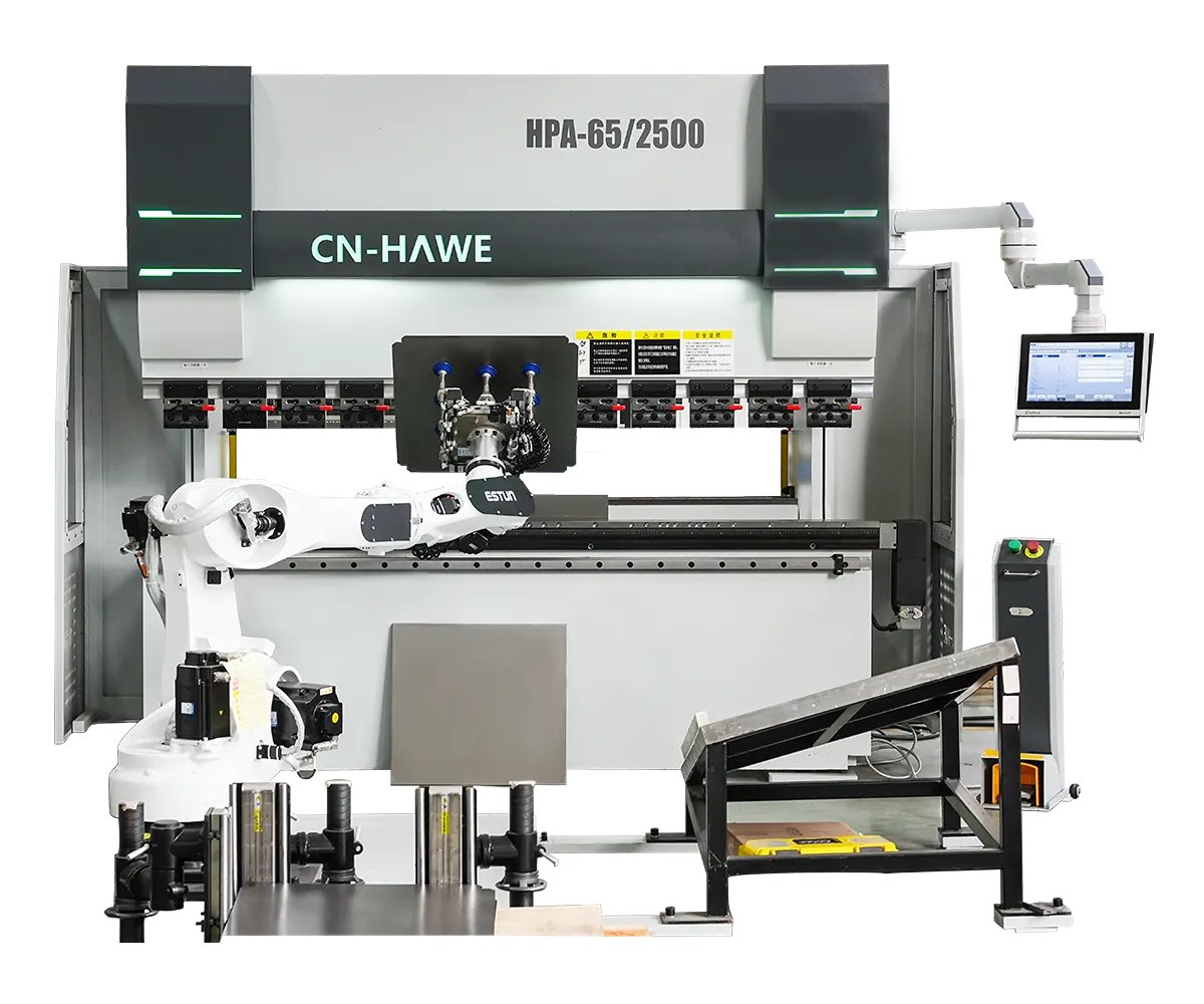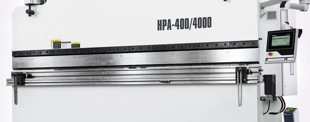

A press brake doesn’t read moods, issue warnings, or think twice—it performs the programmed stroke without exception, whether what’s under the punch is hardened steel or a human hand. This fact can rattle newcomers, but it shouldn’t freeze them into inaction. The goal is to replace vague worry with informed respect: understanding exactly how the machine behaves, why it behaves that way, and cultivating work habits so the physics remain predictable—and safe. Once you grasp what the ram “recognizes,” mishaps stop seeming random and instead become preventable breakdowns in procedure or safety systems.
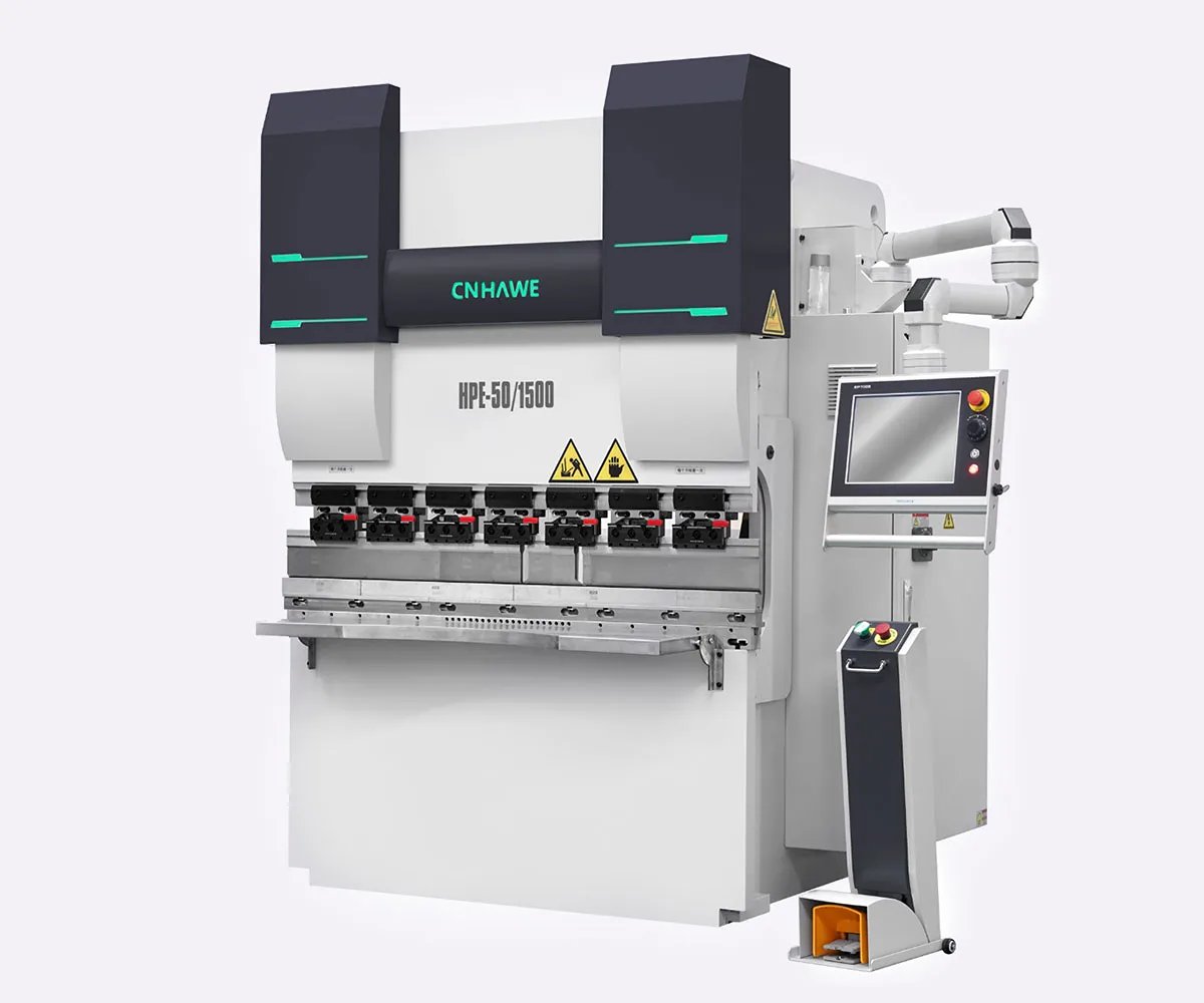
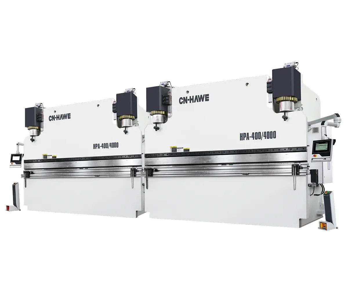
A hydraulic press brake channels anywhere from 40 to 300 tons of force in a vertical, precise stroke, converting hydraulic power through rigid tooling that leaves no margin for compromise. Think of it as a high-accuracy nutcracker—one that never misses, never pauses, and never chooses mercy.
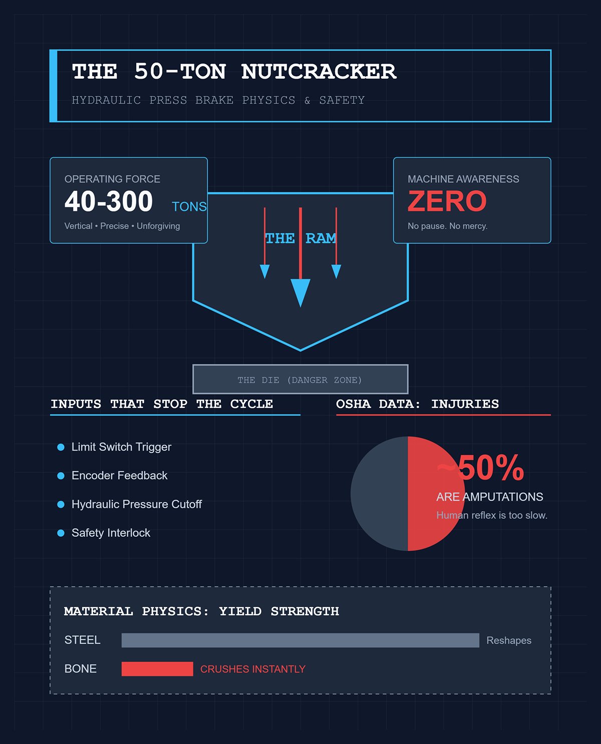
The ram’s movement is devoid of human awareness. Once engaged, it operates to its preset distance, force limit, or programmed bend angle. Only an input like a limit switch trigger, encoder feedback, hydraulic pressure cutoff, or a safety interlock can halt or slow it. Without such intervention, it delivers the full force until the cycle concludes. Steel yields and reshapes under this pressure; bone, with its far lower yield strength, is simply another material it can deform without pause.
Predictability cuts both ways. OSHA records confirm that roughly half of all injuries involving hydraulic presses and press brakes are amputations. These incidents most often occur in the working zone—where punch meets die—precisely because the ram behaves exactly as designed and cannot reverse within the fractional seconds a human reflex would require. Acknowledging this isn’t about instilling fear; it’s about building a mental framework solid enough to guide critical positioning and apply safeguards before your foot even grazes the pedal.
The ram’s control system operates on a simple assumption: whatever sits between the punch and die is the intended workpiece. Variations in hardness, the presence of gloves, or even human flesh don’t influence its decision to proceed. The hydraulic circuit will apply the programmed force until the cycle is complete. Voices, sudden movement, or mere proximity make no difference—unless they break a safety beam or trigger a protective relay.
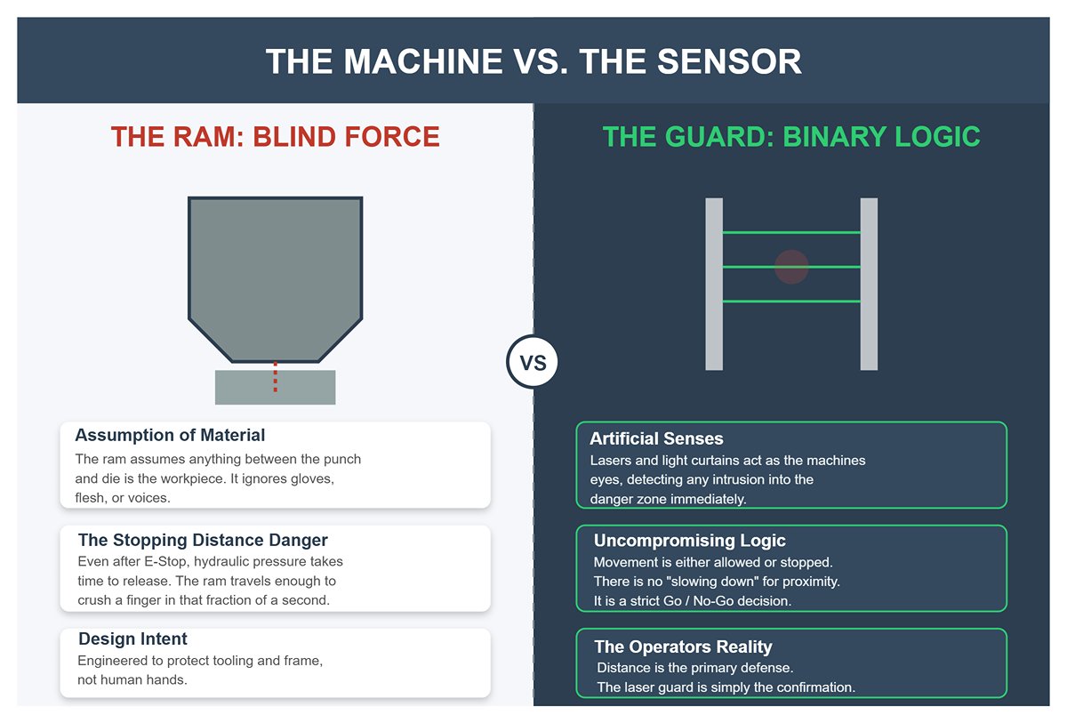
This lack of sensitivity is striking when you consider stopping distances. Even after hitting the emergency stop, the ram must release hydraulic pressure, continuing to travel for a critical fraction of a second—enough to crush far beyond the thickness of a human finger. The control system is engineered to protect tooling and the machine’s frame from overload, not to react to the unexpected presence of a hand.
Safety mechanisms bring a measure of awareness to an otherwise uncompromising machine. Laser guards, light curtains, and “B-gates” serve as artificial senses, detecting an intrusion into the danger zone and immediately halting or preventing operation. Their logic is as uncompromising as the ram’s: movement is either allowed or stopped—never slowed because something is “close.” Operators who grasp this reality understand that maintaining full clearance from the tooling is their best defense; the laser guard is simply the confirmation.
At the start of the day, treat press brake setup as your prime safety opportunity. Once the ram starts moving, the only barriers between safe production and injury are the guarding systems—and your own vigilance.
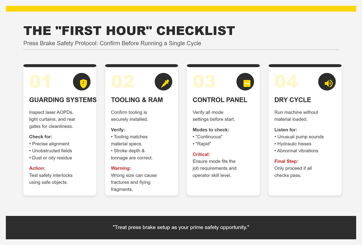
Inspect all guarding equipment—laser AOPDs, light curtains, and rear gates—for cleanliness, precise alignment, and unobstructed detection fields. Dust, oily residue, or shifted mounts can compromise their performance or give falsely clear signals. Test safety interlocks using safe objects to ensure they respond correctly.
Confirm that all tooling is securely installed and suited to the day’s material specifications. A punch or die of the wrong size can cause the material to fracture unpredictably, potentially sending sharp fragments flying. Check that the ram’s programmed stroke depth and tonnage correspond correctly to the material’s thickness and tensile strength.
Verify the control panel’s mode settings. Certain modes, such as “continuous” or “rapid,” significantly shorten the time available for intervention in case something goes wrong. Make sure the chosen mode is appropriate for both the job requirements and the skill level of everyone involved.
Before starting actual production, run the machine through a dry cycle—no material loaded—and keep well clear of the working area. Pay close attention to any unusual sounds from the pump, a hiss from the hydraulics, or abnormal vibrations, as these can signal issues that threaten both accuracy and safety. Only once all checks have passed should you place the material, engage the foot pedal, and let the ram operate. This consistent discipline fosters respect for the equipment: a preparedness routine that transforms apprehension into confidence in both the machine’s reliability and your own skill.
Fabrication drawings come loaded with details—dimensions, tolerances, material types, and finish notes—but a hydraulic press brake is only affected by a select set of these. Your first responsibility as an operator is to distill the drawing down to the elements that influence bending: material type and thickness, bend angles, required inside radii, flange lengths, and the bending sequence. These core values dictate which tooling to use, how to calculate tonnage, and where to position the backgauge.
Misinterpreting or missing any of these critical details can spark a chain of failures. An incorrect thickness leads to wrong tonnage settings; a misread bend sequence can cause the part to collide with tooling after an initial bend, forcing a redo. Some errors can be corrected mid-run through programming adjustments, but poor tooling choices or tonnage miscalculations can result in scrapped parts or damage to the ram and bearings. Accuracy at this stage safeguards your workpiece and the hydraulic system, which delivers massive force with zero tolerance for approximation.
Take a drawing specifying stainless steel at 1.0 mm thickness with a tight internal radius—this demands different tooling than an aluminum sheet of identical thickness. Stainless steel has greater springback, so the tonnage chart must be interpreted accordingly. This is why experienced operators set aside dedicated time to read a drawing in mechanical terms as well as geometric ones: the goal is to convert visual specifications into the operating language of the press brake.
In bending operations, the punch shapes the top of the bend, the die forms the underside, and the width between the die’s shoulders—known as the die opening—dictates how the sheet responds to pressure. A dependable guideline is the “8x Rule”: for standard air bending, choose a die opening about eight times the thickness of your material. Opting for a narrower opening can deliver higher precision up to a certain point but will significantly increase the tonnage required, raising the risk of overloading. Conversely, a wider opening lowers tonnage but compromises bend accuracy and can create an overly large bend radius.
Take, for instance, a 3 mm thick mild steel panel. According to the 8x Rule, a 24 mm die opening is ideal. Reduce that to 12 mm (4x) and the required tonnage can surge by approximately 200–300%, placing extra stress on the ram and cutting tool life short. Increase it to 36 mm (12x) and the bend will appear flatter, necessitating overbending to meet specifications—adding extra cycle time and introducing variability.
This principle isn’t some arbitrary training-room tip—it’s grounded in the physics of load, deflection, and the material’s yield strength. Straying from it unnecessarily invites mechanical stress, premature wear on hydraulic components, and subpar part quality. If production demands require pushing beyond the rule—for example, to achieve a specialized design—do so with deliberate intent and an awareness of the machine’s rated capacity.
The backgauge acts as your precision locator for the material, ensuring each blank is correctly positioned before every bend. Its accuracy determines whether subsequent bends align perfectly or gradually distort the part. The first programmed stop is pivotal—it establishes the reference point from which all other offsets are calculated. Get that first stop wrong, and small errors will accumulate throughout the process.
Picture fabricating an L-shaped part with four bends. If the first flange is misaligned by 0.5 mm because of an inaccurate backgauge setting, that error will repeat and compound with each reorientation, potentially throwing the final flange length out by 2–3 mm. On tight-tolerance projects, that margin could mean the difference between a pass and a wasted part.
Calibration must take into account tooling alignment, ram stroke limits, and proper sheet support. The backgauge fingers should meet the material squarely, avoiding any deflection or twist. Hidden sources of inaccuracy like looseness in the backgauge drive or poorly aligned stop faces can quickly erode precision. A diligent operator will confirm the first stop through both visual alignment and a trial fit before beginning production—ensuring every bend starts from a reliable, true reference point.
Scrap testing is more than just playing it safe—it’s a deliberate, controlled trial. Even with meticulous setup, variables like material inconsistencies, springback, and tooling wear can sneak in to throw off bend angles or flange lengths. Performing a test bend on a non‑critical blank lets you validate your setup and uncover potential issues before loading the machine with production parts.
Never risk a production piece for this step. If your bend is wrong, you’ve wasted both the material and the prep effort. Scrap tests reveal problems such as over‑ or under‑bending, twist, and surface marking. They can also expose more subtle issues—like a slightly worn punch affecting bend radius, or hydraulic drift over repeated strokes—that static checks might miss.
Scrap testing is especially valuable when fine‑tuning programs. Adjustments to ram depth or backgauge position after a test take just minutes, whereas fixing misbent production parts can consume hours and cause delays for customers. Even in high‑volume manufacturing, investing two minutes in a scrap bend can prevent major downtime and costly rework.
The first fifteen minutes of setup define the accuracy and efficiency of every cycle thereafter. In hydraulic press brake operations—where tooling and hydraulics can deliver over twenty tons of force in moments—starting with exacting precision is essential. Errors such as misreading a drawing, selecting tooling without applying the 8x Rule, sloppy backgauge placement, or bypassing scrap tests inevitably lead to wasted material, equipment damage, or both.
The progression here is from being merely prepared to achieving consistent dependability. By rigorously following these setup practices, you move beyond simply knowing what defines a safe operation—you actively create conditions where every bend begins flawlessly, meets specified tolerances, and keeps the press brake performing optimally. Those fifteen minutes aren’t wasted time; they’re a proactive safeguard against every avoidable issue you might encounter on the shop floor.
In modern hydraulic press brake work, air bending has become the preferred technique for good reason—precision combined with efficiency. This method positions the punch above the workpiece, stopping short of contacting the die’s base. The CNC system calculates the precise ram depth needed to achieve the desired angle and automatically compensates for springback. Air bending greatly reduces strain on both tooling and material, prolongs tool life, and delivers consistent accuracy—without requiring constant fine-tuning by the operator.
Bottoming, on the other hand, presses the punch and material firmly into the die until the angle is fully formed. While it has its place—such as with thick materials or extremely short flanges—it dramatically increases the tonnage needed and accelerates wear. Many operators mistakenly bottom parts to counteract springback, but the real fix lies in selecting the correct tooling—like opting for an 88‑degree punch instead of an 85‑degree punch to control bend recovery—rather than overpowering the stock.
With servo‑driven ram systems, today’s machines maintain positioning accuracy within ±0.01 mm. In practice, that means they’re already delivering exact angles; trying to force the material completely flat risks damaging the workpiece or tooling. The operator’s job is less about adjusting angles by feel and more about ensuring the material is accurately seated against the backgauge and that tooling is correctly matched to the task.
| Aspect | Air Bending | Bottoming |
|---|---|---|
| Technique | Punch stops above workpiece, not contacting die base; CNC calculates precise ram depth and compensates for springback | Punch and material are firmly pressed into the die until the angle is fully formed |
| Precision & Accuracy | High precision with CNC and servo control; maintains ±0.01 mm positioning accuracy | Can be precise but often used to counter springback through force rather than tooling choice |
| Tool & Material Strain | Reduced strain, prolongs tool life, consistent accuracy without constant fine‑tuning | High strain, increased wear on tooling and material |
| Tonnage Requirement | Lower tonnage needed | Dramatically higher tonnage required |
| Springback Management | CNC compensation or correct tooling (e.g., 88° punch) to control bend recovery | Often misused to force out springback instead of selecting proper tooling |
| Operator Role | Ensure correct tooling and proper material seating against backgauge | May require more manual angle adjustments; risk of damaging workpiece or tooling if forced completely flat |
| Ideal Use Cases | General precision bending; efficiency with varied materials | Thick materials or extremely short flanges |
On older press brakes, a rapid descent of the ram could cause the free edge of the sheet to snap upward—a motion known as “whip-up”—posing both a safety risk and potential damage to the material. To avoid injury, operators would stand well clear and support the sheet from a distance. In contrast, modern hydraulic systems carefully regulate ram acceleration and deceleration, greatly reducing this effect. Advanced features like automatic bend sequencing and controlled approach speeds further minimize unexpected movement.
While this advancement reduces hazards, hand placement still matters—just for a different reason. Rather than bracing against the sheet’s motion, the operator’s aim is to maintain stability and precise alignment. Hands should remain clear of any pinch points and rest lightly on the sheet, preventing sideways slip without fighting the machine’s guided movement. Standing in a position that faces the backgauge offers a clear view of both the edge seating and bend progress, while keeping the operator’s arms and torso safely outside the tooling area.
This method is as much about mindset as it is about mechanics—it frames the operator’s role as a guide rather than a counterforce. Allowing the machine to perform the bend eliminates unnecessary physical strain and keeps attention focused on critical factors such as proper gauge contact, cleanliness of the material, and ensuring nothing obstructs the ram’s programmed path.
In the past, operator speed was often tied to how deftly one manipulated the foot pedal—carefully feathering it to accelerate the ram’s approach, then slowing as it reached the target bend depth. Modern press brakes build rapid approach speeds—up to 260 mm/s—directly into their motion profiles, automatically initiating precision slowdown during bending. With timing handled by the machine, attempting to rush pedal inputs only risks bypassing safety interlocks or knocking the sequence out of order.
Today, the definition of “fast” is synonymous with “consistent.” The most productive operators treat the pedal as a simple on–off control—press, hold, release—while focusing on moving and aligning material swiftly between bends. Time savings stem from confident setups, quick and accurate alignment to the backgauge, and avoiding time-consuming corrections due to misalignment or bending errors.
Once the pedal is engaged, the hydraulic system’s programmed logic takes over entirely. Resisting the temptation to “assist” the machine allows operators to shift focus to the next bend, check bend accuracy, and confirm that tags or documentation stay aligned with production flow. In high-volume operations, this disciplined approach shortens overall run time—not by speeding up the mechanics, but by streamlining operator actions.
Bend sequence isn’t about personal preference—it’s critical for preventing tolerance buildup and avoiding workflow issues. Every bend influences the geometry of the next, and even if angular accuracy is perfect, minor variations in flange length can add up. If bends are sequenced poorly, these deviations can land on the final flange, where fixing them without rework is impossible.
Experienced operators plan order directly from the print, arranging bends so that any minor dimensional differences are distributed across the part. This often means starting with the largest flanges or organizing bends to keep the workpiece firmly against the backgauge as long as possible. Maintaining stable backgauge contact ensures each bend is consistently positioned before the part’s geometry becomes more complex.
Even with advanced crowning and automated compensation, bend sequence still determines whether a part fits at assembly. A component can have precise angles but still fail if accumulated error shifts hole placement, tab lengths, or mating angles. This is where an operator’s grasp of the finished product directly shapes process success.
Many training programs still stress manual finesse—guiding the bend with hand input and modulating pedal speed—as though the machine needs coaxing. But with today’s servo-controlled systems, that mindset can introduce more error than control. A better way to begin is by pinpointing exactly when, in the bend cycle, automation takes over—and making a conscious effort not to interfere.
Choose tooling designed to manage springback rather than forcing extra tonnage through bottoming. Keep your hands clear of the pinch zone so you’re not inadvertently adding resistance, operate the foot pedal as intended without manually varying its speed, and plan your bend sequence to spread tolerances in a smart, deliberate way. In essence, collaborate with the machine instead of working against it. Operators who embrace this move from mechanical “fixes” to guided precision tend to boost throughput, extend tooling life, and deliver consistently accurate parts—without the fatigue or safety risks of outdated habits.
Springback—the tendency of metal to elastically return toward its original form after bending—is a leading cause of angle discrepancies. If a flange rebounds beyond tolerance, the operator needs to catch it before the run goes further. For example, when the controller targets 90° but the free flange measures 92–93°, that’s mild steel’s elasticity at work. In many production settings, intentionally overbending low-carbon steel by about 2–3° is standard, with higher‑strength materials requiring proportionally greater overbend. Certain high‑strength alloys may need 4–6° depending on cross‑section and the die used.
Variation in material is another frequent cause. Identical machine settings can yield different angles when using a new coil or supplier batch. Changes in yield strength from lot to lot can suddenly alter springback behavior; even within spec, slight shifts in tensile properties can produce noticeable angle changes. Treat each new material batch as a fresh setup—use scrap from that batch to run tests before committing your good stock to production.
Die width plays a pivotal role in springback control. A V‑die that’s much wider than recommended increases the bend radius and elastic recovery, making angle correction via programming alone more difficult. Narrowing the die opening from roughly 12× the material thickness to 8× can reduce springback by up to 40%. If you’re seeing persistent underbends despite programmed overbend, reconsider your tooling choices before assuming the machine is at fault.
The state of your tooling is just as important as its dimensions. A punch with a worn nose or a V‑die shoulder that’s nicked or damaged changes the way the metal contacts the tools, which can lead to visible angle differences along an otherwise uniform bend. If only one section is consistently off by one or two degrees while the rest is within spec, it’s likely due to wear or damage. In such cases, it’s better to repair or replace the faulty die rather than trying to compensate through CNC offset adjustments.
With thicker or high‑strength materials, miscalculating tonnage can result in a less obvious but equally problematic failure: the bend never fully enters the plastic deformation stage. Without sufficient force, the workpiece will never reach the programmed angle, no matter how many repeat hits you make at the same depth. To avoid this, calculate tonnage accurately by taking into account the material’s tensile strength, its thickness, and the chosen die width.
A few quick diagnostic checks can significantly improve an operator’s troubleshooting speed:
Crowning — the press brake’s ability to counteract deflection under load — is essential for producing uniform long bends under heavy tonnage. Without proper compensation, the ram and bed deform slightly in opposite ways during bending: the bed sags while the ram arches upward. This reduces penetration at the center compared to the ends, leaving the middle of the bend more open than intended.
A simple test can confirm crowning issues. Measure the angle 50–100 mm from the left end, right at the center, and 50–100 mm from the right end. If the ends are accurate but the center is open, crowning is insufficient. If the ends are correct but the center is overly tight, crowning is set too high. When one end differs from the other, the root cause is often ram misalignment or improper tool seating.
The “flip test” can help pinpoint the source. Bend a flange and note which side shows the error. Then rotate the workpiece end‑for‑end and bend another flange. If the same side of the press brake produces the fault, the issue lies within the machine or tooling on that side. If the same side of the part is faulty after flipping, the stock itself is at fault, due to uneven thickness or variations in hardness.
Accurate crowning adjustment is key to maintaining consistent bend angles throughout the full length of a workpiece. Whether using mechanical or hydraulic crowning, the system must be fine-tuned to match the specific material, workpiece length, and tonnage requirements. Skipping this step on longer pieces almost inevitably leads to angle deviations at the center.
Surface imperfections are often dismissed as inevitable, but most have clear, fixable causes. Marks along the bend line typically stem from worn die shoulders, grit embedded in the tooling, or punch radii that are too small, concentrating force onto limited contact areas. Even tiny burrs or dents on the tooling can leave visible blemishes on the finished piece.
Regular die and punch upkeep offers a straightforward solution: ensure all contact surfaces are clean and free from debris. Any particle lodged between workpiece and die can leave an impression under pressure. Using soft overlays—such as polyurethane film or thin sacrificial sheets—can protect delicate surfaces without significantly affecting bend angles, provided you factor them into your setup.
Tooling choice also impacts surface finish. Dies with larger shoulder radii spread the contact force over a wider area, lowering the chance of creases or burnish marks, especially on softer metals. For coated or mirror-polished sheets, switching to polished tooling or applying an intermediate protective layer is often enough to safeguard appearance.
Scratches that run beyond the bend zone usually result from dragging during placement or removal. Check that backgauge faces and support arms are clean, smooth, and free of burrs. Careful handling during loading and unloading, combined with consistent cleaning routines, helps prevent most unintended damage.
Cracks forming along the bend line indicate a structural failure, not just a surface flaw. One of the most common contributors is the relationship between grain direction and bending. During rolling, sheet and plate metals develop a grain structure; bending parallel to this grain increases fracture risk, especially in hardened or brittle alloys.
A quick visual check can help avoid expensive errors: look for rolling marks or mill lines to determine grain orientation. Whenever possible, bend perpendicular to the grain to reduce the stress that can split it apart. If bending perpendicular isn’t an option, increasing the bend radius will reduce tensile strain at the outer surface, or select a material grade with greater ductility.
Material thickness and hardness significantly increase the likelihood of cracking. Thicker sections focus the strain into a smaller area, while high-hardness steels have less capacity to stretch before breaking. Choosing a punch nose radius that suits these material properties allows the strain to be spread more evenly across the bend. For high-value components, run test bends on scrap from the same batch prior to working with costly blanks to avoid expensive errors.
Some fractures start microscopically, remaining hidden until they expand during finishing or in actual use. A careful inspection right after bending can reveal early warning signs: minuscule surface tears or dull patches where the bend should have a clean, uniform shine. Detecting these imperfections early makes it possible to repair the part or adjust the process before the flaw worsens.
Many troubleshooting manuals miss a crucial point: errors in bend angle, crowning discrepancies, surface blemishes, and cracking can often be spotted right away in the finished workpiece, not just during later quality checks. The most valuable habit for a press brake operator is to practice in-process triage—stop after producing the first piece in a batch, check bend angles along the entire length, examine the surface, and look for cracks. Adjust tooling or machine settings before proceeding. This single step can save dozens of parts from being scrapped by catching mechanical, material, or setup problems in the moment. It reflects the skill of an operator who blends the machine’s automation with their own keen observation to uphold precision.
Guarding provides your primary safety layer, but it’s no substitute for overall risk awareness. OSHA-approved systems—such as Active Opto-Electronic Protective Devices (AOPDs), light curtains, and laser scanners—monitor the press brake’s work area during ram descent, detecting when something encroaches into the danger zone. They prevent hands, fingers, or other body parts from being caught as the tooling closes, and can also intercept accidents triggered by an unintended press of the foot switch or a mechanical fault like a stuck clutch.
However, these protective systems are not all-encompassing solutions. They won’t shield you during die changes when the press brake isn’t cycling but your hands are between the tooling. They can’t eliminate the risk of a workpiece snapping back during bends on springy material, nor can they guard against pinch hazards at the backgauge or along the machine’s sides. They don’t replace the need for visually confirming clearance before engaging the cycle, and they offer no protection from setup errors that cause the part to twist or shift unexpectedly.
Real safety comes from using guarding as one element in a comprehensive approach—combined with intentional hand placement, vigilance during backhauling, and a pause before any tooling change to verify lockout/tagout compliance. An operator who appreciates the limits of guarding avoids relying on it as a sole safety net. That’s the shift from counting on the machine to counting on skill and judgment.
A flawless bend in winter and a misaligned angle in summer rarely occur by chance—the culprit is usually skipped maintenance. Hydraulic systems demand attention: fluid viscosity varies with temperature, seals experience minute wear every cycle, and fine contaminants slowly accumulate in the reservoir. Each of these factors can subtly influence ram speed and pressure stability, translating into diminishing angle accuracy if left unchecked.
Daily routines are your greatest safeguard. Clean tooling surfaces and check for burrs that might throw stock out of alignment. Confirm ram parallelism at the start of each shift using a feeler gauge rather than relying on sight. Track hydraulic fluid condition weekly—both level and clarity—and replace sooner than the manufacturer’s timeline if contamination is visible. Inspect backgauge leadscrews and linear guides monthly to stop backlash from eroding positioning precision.
For the dedicated craftsman, these inspections are not drudgery but a protective investment—ensuring the machine performs today exactly as it did weeks ago. Absolute precision is unattainable, but stable, repeatable results are well within reach when wear, drift, and contamination are addressed before they silently impede performance.
Experience isn’t just about clocking years—it’s reflected in the way an operator reasons through the work. One of the most effective ways to gauge genuine competence is by asking three targeted questions:
If a trainee answers these with confidence and solid reasoning, they’ve moved beyond rote procedure into true comprehension. If they can’t, they are still mimicking motions—safe only until the unexpected occurs.
An operator can start bending parts within a day, achieve basic proficiency in a week, and reach full competence in a month. But the leap from a $36,000-a-year button-presser to a $56,000-a-year craftsman lies in the narrow, intentional gap between simply pressing the pedal and understanding exactly why the machine responds as it does. Guarding safeguards your life. Maintenance preserves your angles. Asking the right questions keeps your mind sharper than your tools.
Neglect any of these, and your success depends on luck. Master all three, and both precision and safety become certain.