

He had a four-foot aluminum panel clamped in a bench vise, two cheater bars slipped over the handles of a manual “shop bender.” First pull looked fine. Second pull, the panel lagged behind the clamp, bowed in the middle, then snapped upward and smacked him in the forearm.
He thought he needed more leverage.
What he needed was different physics.
You learned on tube. Everybody does. A pipe bender grabs a round section, supports it in a die, and rolls it through a controlled radius. The material is confined on all sides. The load wraps around the curve.
Flat sheet doesn’t get that luxury.
When you try to bend a 36-inch-wide panel with a clamp-and-pull tool, the force travels unevenly across the width. The edges move first. The center lags. That lag is what caused that aluminum to whip upward like a leaf spring unloading on a truck axle.
[Apprentice Rule] If the material can twist, it will twist before it bends.
Always test this on scrap first.

Take a one-inch steel tube in a pipe bender. The die matches the tube’s diameter. Contact is continuous around the arc. The tool dictates the shape.
Now lay a 24-inch sheet under a clamp bar. You’re contacting it along a thin line. Everything past that line is free to flex until the stress exceeds yield strength. That’s not guided bending. That’s controlled chaos.
A tube resists deformation because its closed cross-section spreads stress around its circumference. A flat sheet has no such backbone; its stiffness depends on width and thickness, and across wide spans it behaves like a diving board.
Different geometry. Different load paths.
Treating sheet like pipe is like using a muffler expander to set wheel bearing preload—wrong contact surfaces, wrong result.
[Apprentice Rule] Match tooling geometry to the material’s cross-section, not your muscle memory.
Always test this on scrap first.
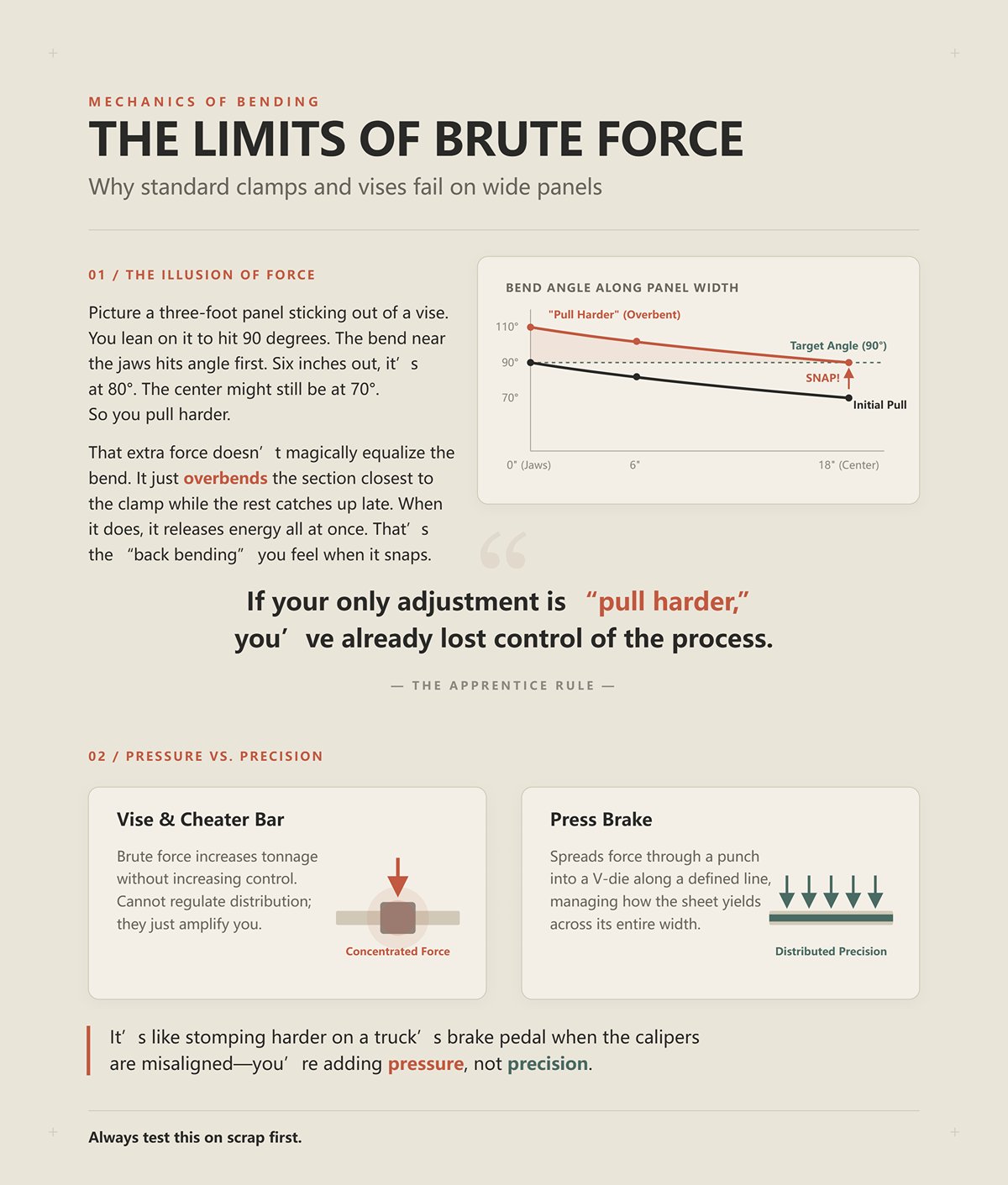
Picture a three-foot panel sticking out of a vise. You lean on it to hit 90 degrees. The bend near the jaws hits angle first. Six inches out, it’s at 80. The center might still be at 70. So you pull harder.
That extra force doesn’t magically equalize the bend. It just overbends the section closest to the clamp while the rest catches up late. When it does, it releases energy all at once. That’s the “back bending” you feel when the panel snaps upward.
Brute force increases tonnage without increasing control. A press brake spreads force through a punch into a V-die along a defined line, managing how the sheet yields across its entire width. A vise and cheater bar can’t regulate that distribution; they just amplify you.
It’s like stomping harder on a truck’s brake pedal when the calipers are misaligned—you’re adding pressure, not precision.
[Apprentice Rule] If your only adjustment is “pull harder,” you’ve already lost control of the process.
Always test this on scrap first.
Stop saying “fold.” That word tricks you.
You’re not folding laundry. You’re driving a punch into a die, forcing material past its yield point along a controlled axis, accounting for springback—the metal’s tendency to relax after load is removed. That relaxation is measured, predicted, compensated.
When shops chase accuracy—snap-fit tabs, interlocking panels, parts that assemble without fasteners—they aren’t muscling bends into place. They’re engineering geometry so every bend lands within thousandths. That only happens when force is applied through matched tooling, not through forearms and hope.
The cognitive shift is this: power doesn’t create accuracy. Geometry does.
And once you see that, the real question isn’t how hard you can pull.
It’s how the punch and die actually control that force.
I set a strip of 1/8-inch mild steel in a 1-inch V-die and bring a 0.060-inch radius punch down until the depth gauge reads 0.500 inches. The angle comes off the die at 90 degrees. I don’t touch the pressure setting. I swap only the bottom die to a 1.5-inch V opening and hit the same depth.
The angle opens up to roughly 94.
Same material. Same punch. Same machine. Different geometry, different result. So if it’s not squeezing metal like a vise, what is it actually doing?
Watch the contact points.
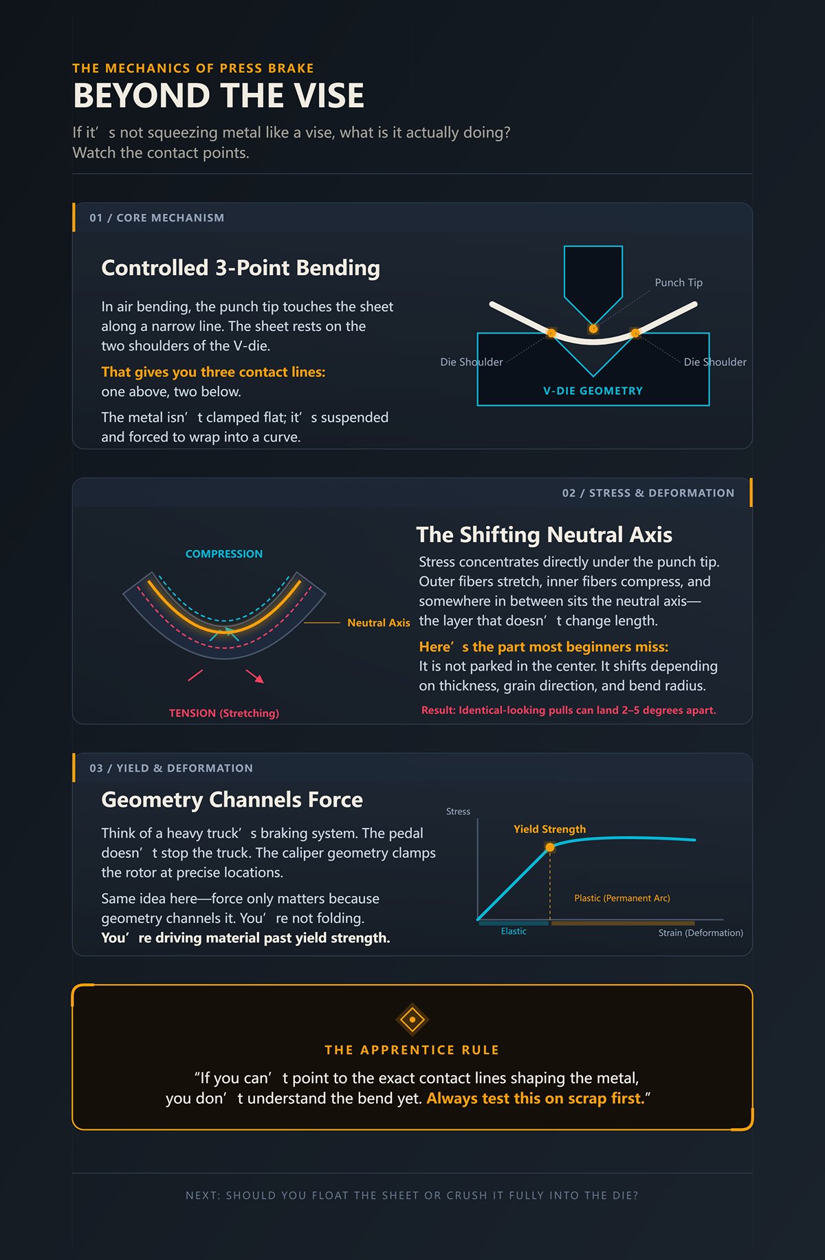
In a press brake, the punch tip touches the sheet along a narrow line. The sheet, in air bending, rests on the two shoulders of the V-die. That gives you three contact lines—one above, two below. The metal between those lines isn’t clamped flat; it’s suspended and forced to wrap into a curve as the punch descends.
That’s not compression like a vise jaw. That’s controlled three-point bending.
Stress concentrates directly under the punch tip. As the punch drives down, the outer fibers of the sheet stretch (tension), the inner fibers compress, and somewhere in between sits the neutral axis—the layer that doesn’t change length. Here’s the part most beginners miss: that neutral axis shifts depending on thickness, grain direction, and bend radius. It is not parked in the center like a painted stripe.
That shifting is why two identical-looking pulls can land 2–5 degrees apart in air bending if you don’t account for material behavior.
Think of it like a heavy truck’s braking system. The pedal doesn’t stop the truck. The caliper geometry clamps the rotor at precise locations, converting force into controlled friction. The shape and placement of the pads determine how the force spreads. Same idea here—force only matters because geometry channels it.
So no, you’re not folding. You’re driving the material past yield strength—permanent deformation—along a defined arc set by punch radius and die width.
[Apprentice Rule] If you can’t point to the exact contact lines shaping the metal, you don’t understand the bend yet. Always test this on scrap first.
But once you see it’s three-point bending, the next question hits you fast: should you let the sheet float between those points—or crush it fully into the die?
Take 14-gauge mild steel. In air bending with a standard 8× thickness V-die ratio (about a 1-inch V for 0.075-inch material), you might need roughly 15–20 tons per foot to hit 90 degrees. Switch to bottoming—where the punch forces the material fully into the V cavity—and that tonnage can jump to 60–100 tons per foot.
Four to eight times more load.
Why? Because bottoming doesn’t just yield the outer fibers. It plastically deforms nearly the entire bend zone to match the die angle. You’re no longer forming an angle by depth control; you’re imprinting the die’s geometry into the sheet.
Bottoming routinely holds ±0.5 degrees. Air bending more often lands around ±2 degrees unless you dial in compensation. Sounds like bottoming is the beginner’s friend.
Until you crack a 0.040-inch aluminum sheet because you exceeded its elongation limit.
Bottoming gives tighter angular tolerance, but it removes forgiveness. Any thickness variation, any grain-direction difference, any tonnage spike gets multiplied by that higher load. Thin sheets and soft alloys don’t negotiate; they tear.
Air bending, on the other hand, forms angle by controlling punch depth relative to die width. The sheet only contacts at three points. Less tonnage. More adaptability. But angle now depends heavily on consistent material properties and accurate depth control.
For a beginner, air bending teaches control. Bottoming punishes guessing.
It’s the difference between modulating brake pressure on a downgrade versus slamming the pedal to the floor and trusting the ABS to save you. One builds feel. The other assumes perfection.
[Apprentice Rule] Learn air bending first; it forces you to understand depth, die width, and material response instead of hiding behind brute tonnage. Always test this on scrap first.
But air bending opens another problem you can’t ignore: why does simply widening the V-die change the finished angle even when the punch depth barely moves?
| Topic | Details |
|---|---|
| Question | Air bending vs. bottoming: Which method gives a beginner the most control? |
| Material Example | 14-gauge mild steel (0.075-inch thick) |
| Air Bending Setup | Standard 8× thickness V-die ratio (≈1-inch V-die) |
| Air Bending Tonnage | ~15–20 tons per foot to reach 90° |
| Bottoming Tonnage | ~60–100 tons per foot |
| Load Difference | Bottoming requires 4–8× more load |
| Reason for Higher Load | Bottoming plastically deforms nearly the entire bend zone to match die angle |
| Forming Mechanism | Air bending: angle formed by depth control; Bottoming: die geometry imprinted into sheet |
| Angular Accuracy | Bottoming: ±0.5°; Air bending: typically ±2° without compensation |
| Risk with Bottoming | Higher load magnifies thickness variation, grain direction differences, and tonnage spikes |
| Material Sensitivity | Thin sheets and soft alloys (e.g., 0.040-inch aluminum) may crack if elongation limit is exceeded |
| Forgiveness | Bottoming: low forgiveness; Air bending: more adaptable |
| Sheet Contact Points | Air bending contacts sheet at three points |
| Control Factors (Air Bending) | Depends on consistent material properties and precise depth control |
| Learning Impact | Air bending teaches control; bottoming punishes guessing |
| Analogy | Air bending: modulating brake pressure downhill; Bottoming: slamming pedal and trusting ABS |
| Apprentice Rule | Learn air bending first; understand depth, die width, and material response |
| Best Practice | Always test on scrap first |
| Open Question | Why does widening the V-die change the finished angle even when punch depth barely changes? |
Set 0.125-inch steel in a V-die that’s 8 times material thickness—1 inch wide. Bend to 90 degrees. Measure the inside radius. You’ll get roughly 0.160 inches, give or take.
Now drop that same sheet into a 12× die—1.5 inches wide. Same punch radius. Same target angle.
Your inside radius increases. Your required punch depth changes. And your springback increases.
Why?
Because die width controls how far apart the lower contact points sit. Wider V means the sheet spans a longer distance between supports. That reduces bending severity per unit depth and produces a larger inside radius. Larger radius means less strain concentration, which changes how much the material elastically recovers after unloading.
The old shop rule—V opening equals 8 to 12 times material thickness—exists because it balances tonnage demand, inside radius, and cracking risk. Too narrow a die spikes tonnage and risks splitting the outer fibers. Too wide a die inflates radius and angle variability.
This is geometry dictating stress distribution. You are choosing the lever arm between the two die shoulders. That lever arm defines how the punch force resolves into bending moment—the rotational force that actually curves the sheet.
Change the lever arm, change the moment. Change the moment, change the angle.
Picture adjusting the track width on a bulldozer. Widen the stance and the way load transfers through the chassis shifts. Same engine. Different geometry. Different behavior.
[Apprentice Rule] Pick your V-die based on thickness and material first; angle comes from that decision, not from stomping the pedal. Always test this on scrap first.
Now you’re thinking like a fabricator. But even with the perfect V ratio, even with textbook punch geometry, something still opens your 90 into an 82 the second the ram lifts.
Bend a strip of 4140 alloy steel to 90 degrees in air. Release the ram.
It springs back to 100.
That’s not a mistake. That’s elastic recovery.
When you bend metal, only the outer portion of the thickness yields permanently. The inner portion may still be within elastic range—meaning it wants to return to its original shape once load is removed. High-yield-strength materials like 4140 resist permanent deformation more than mild steel. So they spring back more—sometimes over 10 degrees in air bending.
Even with an ideal 8–12× V-die ratio.
That’s why experienced operators overbend intentionally. If you need 90 degrees in 4140 and expect 10 degrees of springback, you drive to 80. Not by guessing—by testing and recording.
Here’s where beginners get burned: springback amplifies errors in multi-bend parts. Miss your first bend by 2 degrees, compensate poorly on the second, and tab alignment can drift beyond tolerance fast. Geometry sets the potential. Material yield strength hijacks the outcome if you ignore it.
It’s like setting brake bias wrong on a loaded rig. The system works, but weight transfer under deceleration changes everything. Ignore that shift and you skid where you thought you had control.
Springback is stored elastic energy releasing when the load path disappears. If you don’t plan for that release, your “perfect” geometry won’t save you.
[Apprentice Rule] Always determine springback experimentally for each material and thickness before running production parts. Always test this on scrap first.
And once you understand that geometry defines the stress path and springback defines the correction, the next hard truth surfaces:
What happens when the machine itself can’t deliver that force evenly across the length of the bend?
I watched a 10-foot brake try to put a 90 into quarter-inch mild steel. The edges hit angle. The center stayed open almost three degrees. Operator cranked the pressure. Second pull, the ends overbent, the middle still lagged, and when the ram lifted the panel looked like a shallow canoe.
That’s what happens when the machine can’t deliver uniform tonnage across the length: the ram deflects. Steel frames stretch. The center of the bed sees less effective force than the edges. On long bends—anything past five feet—you can see 0.010 to 0.020 inches of vertical deflection at center on a mid-sized brake. That sounds tiny until you remember angle in air bending is depth-controlled. A few thousandths difference in penetration becomes degrees of angle error.
More power doesn’t fix that geometry. It often exaggerates it. You’re pouring force into a structure that flexes under load.
Think of it like a heavy truck braking downhill: if the frame twists under load, stomping the pedal harder won’t straighten the chassis; it just locks the wheels unevenly.
So before you start shopping for tonnage, you need to understand what that tonnage is actually fighting.
Set up 0.250-inch mild steel, 10 feet long, air bend in a V-die sized correctly. Using a standard air-bend estimate—P ≈ 650 × S² × L / V—you’ll land around 150–170 tons for that length. That formula assumes air bending, an 8× die ratio, and a safety margin.
Now switch nothing but the material to stainless of the same thickness.
Your required tonnage jumps roughly 1.5×. Not because it’s thicker. Because tensile strength—the stress required to permanently deform the outer fibers—is higher. Thickness sets the section modulus, the geometric resistance to bending. Tensile strength sets how stubborn the material is about yielding.
Thickness is leverage. Strength is attitude.
Beginners fixate on gauge charts and ignore yield strength. That’s how they end up underpowered on high-strength alloys or wildly overpowered on soft aluminum. Aluminum might need roughly 0.55× the tonnage of mild steel at the same thickness. If you guess high “just to be safe,” you’re not adding accuracy—you’re adding stress to tooling and frame.
Here’s where the trap springs: that formula assumes air bending. If you bottom or coin that same 1/4-inch plate to force a tight inside radius, tonnage can quadruple—north of 600 tons for 10 feet. Same thickness. Same length. Different forming method. What changed wasn’t the sheet. It was the contact condition.
What he needed was different physics.
[Apprentice Rule] Calculate tonnage based on thickness, tensile strength, length, die width, and forming method—never on thickness alone. Always test this on scrap first.
But even when your math is dead-on, long bends still come out wide in the middle. Why?
Run a six-foot bend on a machine without crowning. Measure angle at both ends and dead center. It’s common to see the center 1–3 degrees more open, depending on load. That’s ram and bed deflection under tonnage.
Steel obeys Hooke’s Law in the elastic range: stress produces proportional strain. Your brake frame is a giant spring. Under load, it bows upward in the middle. The punch penetrates deeper at the ends because the frame there is supported by the side housings. The center floats.
Crowning is deliberate counter-bow. Mechanical wedges or hydraulic systems push the bed upward at center before or during the stroke so that under load, everything flattens out. You are preloading the machine to cancel its own deflection.
Without crowning, operators compensate the wrong way. They add tonnage. That deepens penetration at the edges first—because that’s where the structure is stiffest—while the center still starves. You chase angle with pressure and end up with overbent ends and an open middle.
It’s like shimming a truck’s brake pads unevenly: more pedal force won’t even out contact; it just overheats the tight spots.
Digital controls now factor cosine corrections, material factors, and safety margins, often hitting ±2% accuracy. But even perfect tonnage math ignores frame deflection unless crowning is set correctly. Calculation without compensation is half a solution.
[Apprentice Rule] For bends over five feet, set crowning before you touch pressure; match compensation to calculated tonnage, not to guesswork. Always test this on scrap first.
And if you ignore that and just keep dialing up force, what fails first?
It isn’t the sheet.
I’ve seen a segmented punch split clean across the radius because someone bottomed thick plate in a die rated for air bending. The machine was “big enough.” The tooling wasn’t.
Tooling has a ton-per-foot rating. Exceed it and the contact stress at the punch tip or die shoulder exceeds hardened steel limits. Microcracks start. One day you hear a sharp report instead of a hydraulic hum. Then you’re sweeping up carbide chips.
And if the tooling survives, the ram bearings and side frames absorb the excess. Repeated overload stretches tie rods and throws parallelism off. Now you’ve built permanent inaccuracy into the machine.
More power doesn’t buy precision. It buys accelerated wear if you don’t respect the weakest link in the load path.
Think of running a bulldozer blade into bedrock at full throttle: the engine might handle it, but the cutting edge and mounting pins take the beating.
[Apprentice Rule] Never exceed the ton-per-foot rating of your punch and die; the tool usually fails before the press does. Always test this on scrap first.
So how do you stay out of that trap before the first stroke?
Start with four inputs written down, not guessed:
For air bending mild steel, use the standard estimate adjusted for your die width. Apply material factors: about 1.5× for stainless, roughly 0.55× for aluminum. Add a 20% safety margin—but stay within tooling rating.
If you plan to bottom or coin, multiply accordingly. Expect several times the air-bend tonnage. That’s not optional; that’s physics from increased contact and plastic deformation through the full thickness.
Then check two more things before you cycle:
Modern estimators in CNC controls handle cosine angle corrections and safety factors faster and more accurately than hand math. Use them. But verify that the output respects your tooling’s ton-per-foot limit and that crowning is engaged for long bends.
Write the number down. Compare it to machine rating and tool rating. Only then do you load the sheet.
Precision in bending comes from calculated force applied through matched geometry, not from owning the biggest hydraulic pump in the building. Next, we’ll walk through how to set up that first bend step by step so the math, tooling, and machine all agree before steel ever yields.
A kid I trained once rolled a 10‑foot stick of 11‑gauge mild steel up to the brake, clamped a random 1/2‑inch V‑die in place, eyeballed a 90, and said, “First pull looked fine.” The flange measured 1.000 inch at the left end, 0.965 in the center, 1.015 at the right. Angle wandered a degree and a half across the length. He hadn’t broken anything. He’d just stacked three small setup mistakes on top of correct tonnage math.
The machine did exactly what the geometry told it to do.
You already know force and crowning have to be calculated before steel yields. Now you’re going to see that tooling geometry and backgauge position must be chosen before your foot even hovers over the pedal, because once the punch touches the sheet, physics takes over and it does not negotiate. Think of the press brake like the air brake system on a loaded semi: pedal pressure matters, but if the shoes and drums don’t match, you’re not stopping straight.
Here’s the workflow that keeps you out of the ditch.
Lay a piece of 0.125‑inch (1/8″) mild steel on the bench. You want a clean 90° bend with an inside radius around 0.125 inch. Your first instinct is to grab the smallest V‑die you can find to “force” that tight corner.
Slow down.
In air bending, the inside radius is not set by the punch tip. It’s largely controlled by the V‑opening width. A common rule of thumb for mild steel is:
So for 0.125-inch material, a 1.0‑inch V (8×) is typical. That yields an inside radius around 0.16 inch. Not razor sharp. Predictable.
Now suppose you ignore that and choose a 0.375‑inch V (3× thickness) to chase a 0.06‑inch radius. Two things happen:
Tooling guides warn against going narrower than about 5× thickness for general air bending. Below that, you’re no longer in the stable, predictable air‑bend range. You’re flirting with bottoming loads and overstressing tooling.
That’s how punches crack. Not from one heroic bend, but from repeated overload beyond their ton‑per‑foot rating.
[Apprentice Rule] Choose V‑opening based on material thickness and forming method first; accept the radius that geometry gives you before you chase a sharper corner with brute force. Always test this on scrap first.
If the print truly calls for a sharp inside radius equal to thickness or less, you don’t “cheat” it with a tiny V. You either bottom with tooling rated for that load, coin with a machine sized for it, or change the design. What changed isn’t your ambition. It’s the contact condition — air bend versus bottoming — and that changes the tonnage math entirely.
So once the punch radius and die width are locked in, what keeps that 1.000‑inch flange from wandering 0.035 across ten feet?
Slide the same 0.125-inch sheet into the die and set the backgauge to 1.000 inch. You’re measuring from the die centerline to the gauge fingers. Good.
Now check your die: 1.0‑inch V‑opening.
Here’s the trap. The minimum flange length for a standard V‑die must generally exceed half the V‑opening width. For a 1.0‑inch V, that’s about 0.500 inch. Shorter than that, and the material has nothing solid to bear on; it can dip into the groove instead of forming cleanly.
If your print calls for a 0.400‑inch flange, your backgauge can be laser‑accurate and you will still fail. The sheet will tip or collapse into the die. Geometry overrules intention.
Backgauge alignment is not just about setting a number. It’s about confirming that number is physically supportable by the die you chose in Step 1.
Now square the sheet against the gauge fingers and check for parallelism across the bed. If your ram and bed are crowned correctly for the calculated tonnage, penetration will be even. If they’re not, the center may open up 1–3 degrees on long parts. That translates directly into flange length variation because angle error changes the projected dimension.
On a 1‑inch flange, a one‑degree angle error can shift the leg length by several thousandths. Across ten feet, that becomes visible.
Setting the backgauge without verifying die width and crowning is like aligning a truck’s front wheels while ignoring a bent axle: the numbers look right, but the vehicle still pulls.
[Apprentice Rule] Before trusting a backgauge dimension, confirm die width supports the flange and crowning matches calculated load across the full bend length. Always test this on scrap first.
You’ve picked the geometry. You’ve set the stop. Now you finally get to bend — but how do you dial in angle without guessing?
Take a 6‑inch offcut of the same material. Same grain direction. Same thickness. Same tooling. Make a single 90° air bend.
Measure it with a calibrated angle finder. Suppose it reads 92°.
That two degrees is springback — elastic recovery after you remove load. Mild steel might spring back 1–3 degrees in typical air bends. High‑strength steels can rebound more.
Do not “just bump it a little more.”
Instead, program or set your target to 88° if you need a final 90°, because experience — and your test — tells you this material springs back 2°. You are intentionally overbending to land on spec after recovery.
Here’s where beginners trip: they test on a long part first. On multiple parallel bends, follow the shortest‑flange‑first rule. Short legs are harder to control and more likely to interfere with tooling. If you dial in springback on a long, easy flange first, the short one may collide or distort later.
Sequence matters.
Air bending typically carries about ±1° inherent variation even on modern CNC brakes. If your tolerance is tighter than that, you may need bottoming with matched tooling — and a full recalculation of tonnage to stay within tool ratings.
What he needed was different physics.
Springback correction is controlled overtravel based on measured elastic recovery, not pedal feel. Think of it like setting brake bias on a heavy truck: you don’t stomp harder; you proportion pressure so both axles do their share predictably.
[Apprentice Rule] Measure the first bend, calculate the springback correction, and change only one variable at a time; never chase angle by feel. Always test this on scrap first.
But what if the drawing demands a flange so short that no amount of angle tweaking makes it possible?
Picture a 0.250‑inch plate in a 2.0‑inch V‑die. Half the V‑opening is 1.0 inch. The print calls for a 0.750‑inch flange.
As the punch descends, the plate contacts the die shoulders. But the material outside the bend line — your intended flange — is shorter than the support span. It has nowhere stable to sit. Instead of forming a clean 90°, it wants to rotate and slip into the groove.
You can clamp harder. Add tonnage. Slow the stroke. The geometry does not change.
In standard air bending with that die, that flange is below the stable minimum. It is not a skill problem. It’s a support problem.
Now — and this is where nuance matters — there are exceptions. Specialized tooling, such as narrow‑shoulder dies or rotary bending systems, can support shorter flanges. Bottoming with sharp punches can sometimes force geometry at higher tonnage. But those solutions demand higher loads or special equipment and must be evaluated against machine and tooling ratings.
Most shop presses are not sized for heroic coining on thick stock.
Calling every short flange “impossible” is lazy. Calling every short flange “doable if you push hard enough” is dangerous. The right question is: does my chosen die width physically support this flange without exceeding tool or machine limits?
That’s not brute force thinking. That’s engineered contact.
[Apprentice Rule] If flange length is less than half the V‑opening, assume standard air bending won’t support it and reassess tooling or design before applying more force. Always test this on scrap first.
Now you can see the pattern: punch radius chosen from thickness, die width selected from stable ratios, backgauge set within geometric limits, springback measured and compensated, and flange length checked against die support. None of that is guesswork.
And once you’ve done it once, the next question stops being “How hard do I hit it?” and starts being “Is this the right machine for the job?”
You’ve engineered the bend on paper. Die width checks out. Flange length is supportable. Tonnage per foot is calculated.
Now the real question: can your machine deliver that force evenly, repeatedly, and without twisting itself into a pretzel?
Machine type isn’t about bragging rights. It’s about control — how precisely you can apply calculated tonnage through chosen tooling, and how consistently you can repeat it over a shift, a week, a year. A press brake is like the braking system on a loaded dump truck: the pedal is useless if the hydraulic lines, master cylinder, and rotors aren’t sized for the load you’re asking them to control.
Bigger isn’t automatically better. Sloppier is always worse.
If you remove this decision from the process, everything we just engineered collapses back into guesswork. So let’s walk through where each type actually fits — and where it quietly sabotages you.
A manual finger brake is not a press brake. It’s a clamping leaf that rotates around a hinge to fold thin sheet.
That matters.
There is no punch penetrating into a V-die. No calculated air-bend geometry. No controlled bottom dead center. You clamp, you pull, the material yields along a line defined mostly by clamping pressure and sheet thickness. It’s closer to bending a license plate over your knee than forming controlled geometry.
So when is it good enough?
When your material is thin — think light-gauge aluminum or mild steel under roughly 16 gauge. When your tolerances are forgiving — plus or minus a couple degrees won’t ruin assembly. When parts are small and flanges are generous. When production volume is low enough that fatigue won’t creep into your hands and distort consistency by the tenth part.
The hidden problem isn’t just strength. It’s repeatability. Manual repositioning between bends introduces stack-up error. By the fifth bend, a half-degree variation becomes visible at the last flange. That’s not because you’re weak. It’s because the tool offers no reference geometry beyond a clamp bar.
[Apprentice Rule] If your print demands controlled inside radius, tight angular tolerance, or repeatable multi-bend geometry, a manual finger brake is the wrong physics for the job. Always test this on scrap first.
Good enough lives in the world of simple boxes and light covers.
The moment your design depends on engineered die contact, you’ve outgrown it.
A modern CNC press brake can hit bend-to-bend tolerances that look impossible to a manual operator — sometimes within a few thousandths on position and within a degree or less on angle — because it measures and controls stroke position precisely every time.
That isn’t magic. It’s feedback.
Where a manual or basic hydraulic brake relies on you to “feel” bottom, a CNC system controls ram depth numerically and can compensate for springback by adjusting overtravel in measured increments. Some systems even monitor deflection and apply crowning automatically. That’s engineered correction, not instinct.
Think of it like anti-lock brakes on a truck: instead of hoping your foot modulates pressure perfectly on gravel, sensors pulse pressure thousands of times per second so traction stays predictable. Same load. Better control.
So is that overkill for a beginner?
If you’re building one-off brackets in a garage, yes. The machine will outclass your process. But if you’re producing parts that must interchange — enclosures, chassis components, anything with parallel bends that stack — CNC isn’t about speed. It’s about eliminating human variability from the force application we already calculated.
Here’s the uncomfortable truth: beginners benefit more from CNC than veterans do. The machine enforces consistency while you’re still learning material behavior.
[Apprentice Rule] If your tolerance stack depends on consistent ram depth and repeatable backgauge positioning, software control isn’t luxury — it’s insurance. Always test this on scrap first.
But control without capacity is still failure.
Which brings us to the part everyone gets wrong.
The tonnage sticker on the side of a brake tells you maximum force. It does not tell you usable precision across length.
You calculated, say, 60 tons for your bend. Fine. But is that across the full working length? At what die width? With what deflection? A light-frame hydraulic brake pushed near its rated limit can deflect in the center, opening your angle by a degree or two over long parts. Same numbers. Different result.
Frame rigidity, bed length, and crowning capability matter as much as raw tonnage.
If most of your work is 0.090-inch aluminum under four feet wide, a massive 300-ton, 14-foot brake is wasted iron. It will never operate in its optimal control range. If you plan to grow into quarter-inch steel at ten feet, that 40-ton hobby brake becomes a liability the first time you try to meet a real print.
Capacity should match your 80 percent workload comfortably — not barely — with headroom for the 20 percent that pushes you.
There’s also an honesty check here. Panel benders can outpace press brakes dramatically on high-volume flat panels because they grip and form multiple bends in one setup, but they struggle with hems, offsets, and non-perpendicular geometry. Press brakes remain the versatile workhorse for complex parts. So your growth path depends on what you actually build, not what looks impressive in a showroom.
Buying for ego is expensive.
Buying for matched geometry is engineering.
[Apprentice Rule] Choose a press brake whose rated tonnage, working length, and control system comfortably exceed your calculated needs for your most common material — not your heaviest hypothetical job. Always test this on scrap first.
Even the right machine has boundaries.
And knowing when not to use a press brake at all is the next lesson you’re going to need.
You stop trying to make a press brake work the moment the part’s geometry no longer matches a punch descending into a die.
That sounds obvious. It isn’t. I’ve watched smart people double the tonnage, reprogram the CNC, and swap dies three times because “on paper” the bend should close. What they were fighting wasn’t force. It was shape. A press brake is a controlled punch-and-die system — like the braking system on a loaded truck, engineered to apply force through designed contact surfaces — and when the contact geometry disappears, you’re just pushing metal around and hoping it listens.
The one thing you carry forward is this: geometry decides the machine before tonnage ever does. That’s non-obvious because most shops blame failure on “not enough power” or “not enough control.” What they needed was different physics.
So how do you recognize that moment early instead of after you’ve scarred three blanks?
A press brake assumes flat stock resting across a V-die, supported on two lines, with a punch creating a third line of contact. Three lines define the bend. That’s the system.
The second you bring in tube or pipe, you’ve lost two of those lines. The material is already curved. It can’t sit flat in the die. Contact becomes point-loaded and unstable, and the wall wants to ovalize instead of form a clean radius. Trying to brake-bend tube is like trying to straighten rebar with a shop vise — the tool isn’t wrong, it’s just not designed for round cross-sections.
You might get a dent. You won’t get engineered curvature.
Holes and notches in flat sheet create the same problem in a quieter way. The die expects continuous support under the bend line. Cut a notch too close, or punch a hole through the bend zone, and you’ve weakened the cross-section right where stress peaks. The punch drives down, the stress concentrates at the edge of the cutout, and cracks start. The print said “simple 90.” The geometry said “fracture.”
Now ask yourself: if the contact surface is broken or curved before you even start, are you still operating a punch-and-die system?
[Apprentice Rule] If your material cannot sit flat and fully supported across the die shoulders for the entire bend length, you are asking the brake to do a different machine’s job. Always test this on scrap first.
But flat sheet is still flat sheet, right?
Here’s where apprentices get confused. Tight radii and multi-bend boxes look complicated, so they assume the brake is the wrong tool.
It’s the opposite.
A press brake shines when you need controlled inside radius, repeatable angle, and consistent flange length across dozens or hundreds of parts. Bottoming or coining — driving the punch deeper to force the material into a defined radius — reduces springback and tightens tolerance. That’s engineered contact. It’s like torquing a cylinder head with a calibrated wrench instead of guessing with a breaker bar; you’re controlling final position, not just applying force.
But there are boundaries even here.
Minimum flange length matters. If your flange is too short to span a good portion of the die opening, the part tips, twists, or crushes. The die can’t support it. You’ll chase angle variation all day and blame the machine. The real issue is that the flange doesn’t give the die enough real estate to work with.
Then come closed boxes.
You bend three sides. The fourth looks easy on the screen. In reality, the previously formed flanges hit the punch body or the machine frame before the last bend can close. You can sometimes use gooseneck punches or stage tooling, but there is a physical envelope inside every brake. When the part grows outside that envelope, you are done. No software update changes throat depth or daylight.
So the sweet spot is precise flat-sheet geometry that can physically move through the machine’s working space without colliding with it.
Which leads to the real question: if the geometry fights that envelope, what do you reach for instead?
If the part’s defining feature is curvature along its length — a continuous arc, not a single bend line — a roll machine wins. Rolls support the material progressively and distribute deformation over distance. A press brake concentrates force at one line. Forcing a long radius with a brake by bump-bending is possible, but it’s approximation. It’s like trying to machine a shaft round with a file; you can get close, but the process itself works against precision.
If the part is round stock or tube, use a rotary draw or mandrel tube bender. Those tools support the inside diameter to prevent collapse while pulling the material around a form die. The support follows the curve. A press brake cannot do that because its support is stationary and linear.
If you need to close small, tight seams on light-gauge parts repeatedly, a dedicated spot or leaf-style bender may outperform a brake because the tooling matches that one motion perfectly. Less adjustment. Less stack-up error.
The decision framework is simple, but you have to be disciplined enough to use it:
If you answer “no” to any of those, stop trying to rescue the job with tonnage.
[Apprentice Rule] When the geometry demands distributed support, internal mandrels, or continuous curvature, choose the machine built around that support system — not the one already bolted to your floor. Always test this on scrap first.
The hard limit isn’t strength. It’s contact geometry.
Once you see that, you stop asking, “Can the brake handle it?” and start asking, “Does this part even belong in a punch-and-die system?”


