

Last winter a shop owner dragged me over to his “new” press brake like it was a newborn calf. Big color touchscreen. Swipe menus. 3D graphics. First job off it? Twenty-four brackets, eight scrapped. Same drifting flange length he had on the old machine.
He kept tapping the screen like it had betrayed him. I kept looking at the side frames.
Something didn’t add up.
On paper, that brake was impressive: CNC control, programmable backgauge, dual cylinders labeled Y1/Y2, and a glossy interface that could draw the part in 3D before a single hit. The sales rep promised tighter tolerances just from “going digital.”
But when we checked the ram during a long bend, the left side bottomed out a hair before the right. Not much. Enough to twist a 36-inch part out of tolerance.
Here’s the shift that has to happen: precision isn’t born in the screen; it’s born in the independent axes that physically move steel — Y1/Y2 for ram parallelism, X for depth, R for height, Z for lateral positioning. If those axes can’t move independently to match your part geometry, the touchscreen is just storefront glass on a shaky frame.
You don’t fix foundation problems with prettier windows.
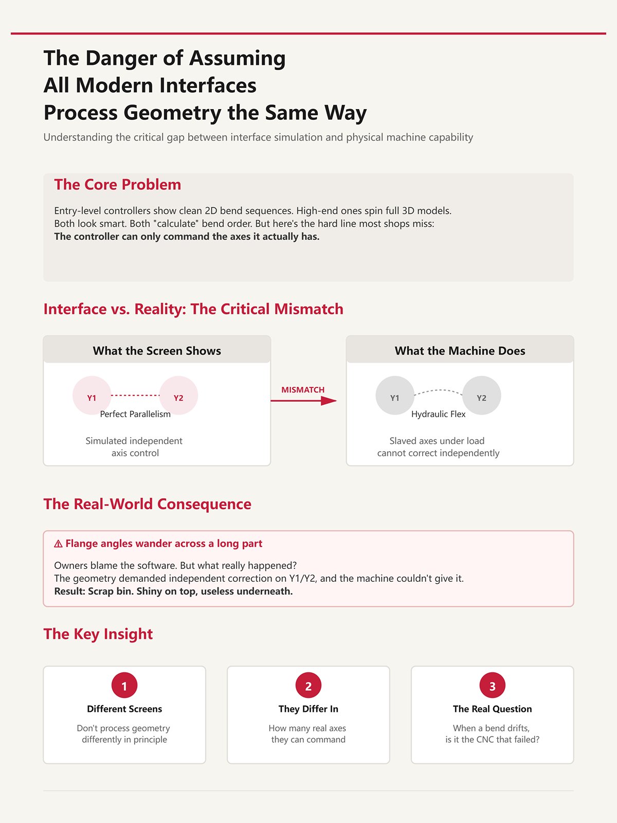
I’ve run entry-level controllers that show a clean 2D bend sequence and high-end ones that spin a full 3D model like a video game. Both look smart. Both “calculate” bend order.
But there’s a hard line most shops miss: the controller can only command the axes it actually has.
If your machine’s Y1/Y2 are slaved together hydraulically instead of independently controlled, the screen might simulate perfect parallelism while the physical ram flexes under load. The interface didn’t lie. It just assumed hardware capability that isn’t there.
I’ve seen owners blame the software when flange angles wander across a long part. What really happened? The geometry demanded independent correction on Y1/Y2, and the machine couldn’t give it. That mismatch goes straight into the scrap bin like mis-cut blanks you can’t un-shear — shiny on top, useless underneath.
Different screens don’t process geometry differently in principle. They differ in how many real axes they can command to make that geometry true in steel.
So when a bend drifts, are you sure it’s the “CNC” that failed?
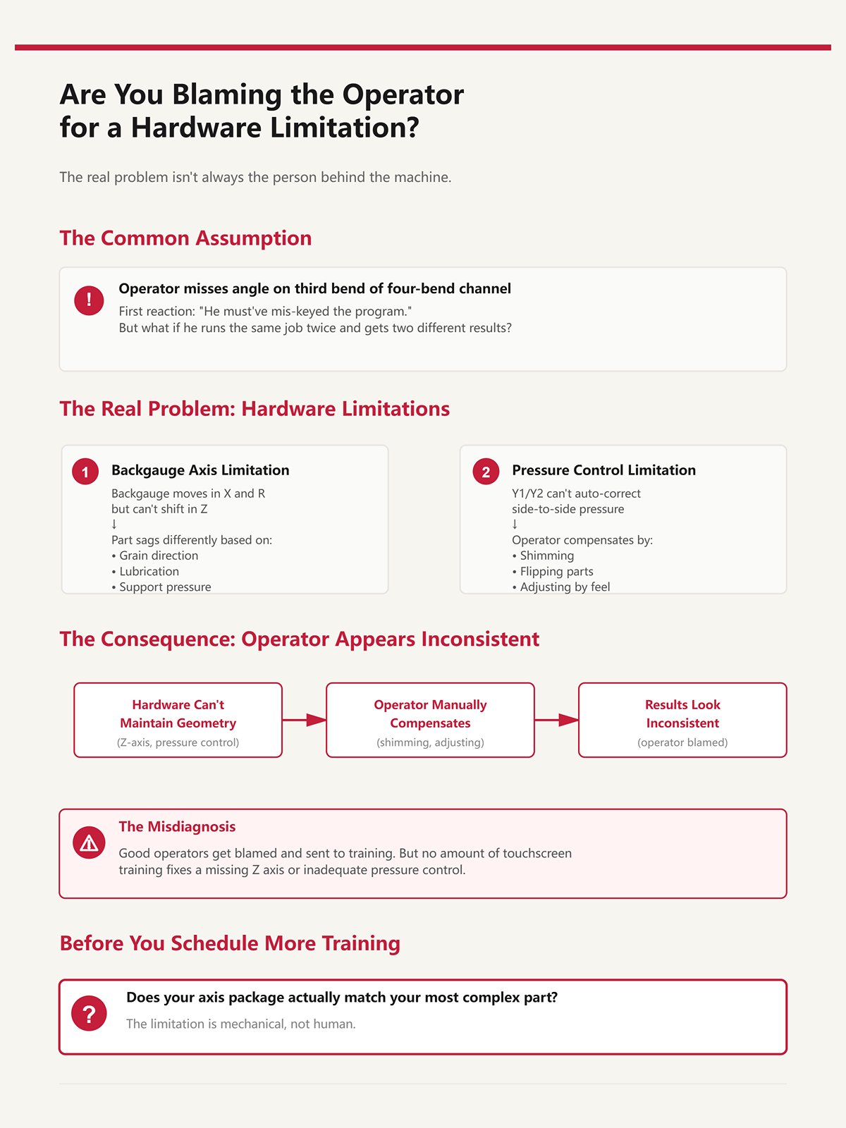
A guy misses angle on the third bend of a four-bend channel. First reaction in most shops? “He must’ve mis-keyed the program.”
Fair question — until you watch him run the same job twice and get two slightly different results.
If the backgauge only moves in X and R but can’t shift in Z to support an offset flange, the part sags differently depending on grain, lubrication, even how hard he supports it. No amount of touchscreen training fixes a missing Z axis. If Y1/Y2 can’t auto-correct side-to-side pressure, the operator starts shimming, flipping, compensating by feel.
Now he looks inconsistent.
What’s really inconsistent is the machine’s ability to match the part’s geometry. We toss good operators into the scrap bin of blame when the limitation is mechanical, not human.
Before you schedule more training, ask yourself: does your axis package actually match your most complex part?

Let’s be fair. Digital controls do change things. Setup gets faster. Programs store. Backgauge repeatability in X can tighten to hundredths of a millimeter. Energy use can drop on servo machines. Those are real gains.
But here’s what often doesn’t change: the number and independence of physical axes.
If your old machine had effectively one ram axis and a basic backgauge, and your new “CNC” still lacks fully independent Y1/Y2 or adjustable Z fingers, the structural capability is the same. You improved communication with the machine. You didn’t expand what it can physically correct.
It’s the difference between repainting a press and upgrading the frame. One feels modern. The other holds tolerance.
So when inconsistent bends survive a touchscreen upgrade, the cognitive shift is this: stop asking how smart the interface is, and start asking whether the axis configuration matches the geometry you’re trying to force through it.
Next question is unavoidable: what happens when Y1/Y2 truly move independently — and what does that change on a long, unforgiving bend?
Picture a 36-inch channel with two offset mounting tabs—left tab short, right tab long. On a 3-axis backgauge (X and R behind Y1/Y2), both stop fingers sit on a single Z beam. You run the first bend fine. Second bend? The right tab hits the finger; the left side floats in air. Operator loosens a clamp, slides one finger by hand, tightens it, eyeballs squareness.
Cycle time just doubled. More important, repeatability just died.
That’s where the real difference shows up. A 3-axis system gives you programmable depth (X) and height (R). For symmetric parts, that’s enough. The backgauge references both sides equally, the ram comes down under Y1/Y2, and life is good. But the moment left and right geometry diverge, a shared Z beam forces compromise. You’re no longer controlling position; you’re negotiating it.
A 6-axis backgauge—X, R, Z1/Z2, plus independent Y1/Y2 up front—lets each finger move laterally on its own. Now the left tab gets its own reference, the right tab gets its own, and the machine stops asking the operator to fake independence with wrenches. The geometry is matched in steel, not in hope.
This is the hard ceiling most shops don’t see coming: when your parts demand independent left-right gauging, a controller without programmable Z1/Z2 isn’t “simpler.” It’s structurally incapable of repeating the job without human intervention.
And human intervention is variability.
Let’s talk load, not theory.
You set R height for a 1/4-inch mild steel flange. Looks perfect in air. Under 80 tons across a long bend, the sheet flexes, the backgauge fingers see upward force, and the part either lifts or digs depending on where it’s supported. If R was set by jogging once and calling it good, that deflection isn’t corrected dynamically.
Angle drift follows.
On a basic X+R setup, the operator compensates by nudging R between hits or by physically lifting the part during the bend. That changes how force transfers into the die shoulders. And once that force path changes, Y1/Y2 can hold ram parallel all day and still produce inconsistent flange angles because the material isn’t seated the same way twice.
This isn’t software confusion. It’s mechanical reference instability.
I’ve watched shops chase half-degree angle swings by recalibrating crowning (V axis) when the real issue was backgauge height interacting with part sag. They were tuning the ram while the part was pivoting on a poorly supported gauge finger. That’s like sorting good blanks into the scrap bin because the shear backstop was loose—you’re blaming the cut when the reference moved.
So yes, Y1/Y2 independence fixes ram skew. But without stable, programmable X and R—and eventually Z1/Z2—you’re still feeding inconsistent conditions into a perfectly parallel ram.
Precision starts before the punch touches steel.
| Section | Content |
|---|---|
| Title | X and R Axes: Why Manual Height Adjustment Sabotages Bend Angle Precision Under Load |
| Introduction | Let’s talk load, not theory. |
| Load Scenario | You set R height for a 1/4-inch mild steel flange. Looks perfect in air. Under 80 tons across a long bend, the sheet flexes, the backgauge fingers see upward force, and the part either lifts or digs depending on where it’s supported. If R was set by jogging once and calling it good, that deflection isn’t corrected dynamically. |
| Resulting Issue | Angle drift follows. |
| Operator Compensation | On a basic X+R setup, the operator compensates by nudging R between hits or by physically lifting the part during the bend. That changes how force transfers into the die shoulders. And once that force path changes, Y1/Y2 can hold ram parallel all day and still produce inconsistent flange angles because the material isn’t seated the same way twice. |
| Root Cause | This isn’t software confusion. It’s mechanical reference instability. |
| Misdiagnosed Fix | I’ve watched shops chase half-degree angle swings by recalibrating crowning (V axis) when the real issue was backgauge height interacting with part sag. They were tuning the ram while the part was pivoting on a poorly supported gauge finger. That’s like sorting good blanks into the scrap bin because the shear backstop was loose—you’re blaming the cut when the reference moved. |
| Conclusion | So yes, Y1/Y2 independence fixes ram skew. But without stable, programmable X and R—and eventually Z1/Z2—you’re still feeding inconsistent conditions into a perfectly parallel ram. |
| Closing Statement | Precision starts before the punch touches steel. |
Run this test in your head.
Take a flat plate. Add a single centered flange. A 3-axis backgauge handles it fine.
Now offset that flange 4 inches to the left. Still manageable; both fingers reference the same edge.
Now add a return flange on the right side only. Suddenly, one finger needs to clear a formed leg while the other must stay tight to an edge. With a shared Z beam, you either retract both fingers or neither. If you retract both, you lose support on one side. If you keep both forward, one collides.
That’s the moment Z1/Z2 stop being luxury and become requirement.
Shops sometimes argue that a 3+1 system—Y1/Y2, X, and crowning—covers “most work.” They’re right for symmetric brackets and channels. But once parts include offsets, hems, or staged bends that change the available reference edge mid-sequence, independent lateral positioning is what keeps depth control consistent from bend one to bend four.
There’s another wrinkle. Some systems offer Delta X—independent depth per finger. Sounds powerful. It is. But if the controller doesn’t synchronize Delta X with Z1/Z2 and Y1/Y2, you can create diagonal misalignment across a multi-bend sequence. One finger advances early, the other lags, the ram stays parallel, and the part twists because your references weren’t coordinated.
Axes don’t help if they don’t move in concert.
So here’s the practical threshold: if your print forces you to think, “I’ll just slide this finger out of the way for this bend,” you’ve crossed into Z1/Z2 territory whether you’ve budgeted for it or not.
Ignore that, and you’re volunteering for inconsistency.
I’ve seen the other extreme.
A shop upgrades to full X, R, Z1/Z2, even Delta X. Six axes on the spec sheet. Big color touchscreen. The first week, homing takes longer than bending because X waits for R to clear, R waits for Z1/Z2 to find limit switches, and one axis faults out if another hits travel early.
Now complexity is the bottleneck.
On some systems, the reference sequence is chained: Z1/Z2 must zero before R moves; R must clear before X finalizes. If one finger reaches its limit prematurely—say a long part required an unusual lateral shift—the entire backgauge pauses. Production feels slower than the old 3-axis machine.
That’s not an argument against more axes. It’s proof of the article’s thesis in reverse: hardware capability only improves precision when the controller can actually calculate, simulate, and coordinate those axes intelligently.
Otherwise, you’ve stacked moving parts without a conductor.
More axes expand the geometric envelope you can hit. Poor coordination shrinks it again through new failure modes—collisions, mistimed moves, reference errors that show up as bent scrap instead of alarm messages.
The foundation matters more than the storefront glass.
And once you add Z1/Z2, the next question isn’t whether you needed them.
It’s whether your controller is smart enough to keep them from fighting each other.
I stood next to a five-axis brake last year—Y1/Y2, X, R, Z1/Z2 all listed proudly on the spec sheet. Big color touchscreen. The programmer loaded a bracket job with three offsets and a return flange. Instead of importing the model, he typed flange lengths and bend deductions line by line from a print taped to the side frame. When the third bend came up short by 0.7 mm, he didn’t blame the axes. He retyped the depth.
That’s the dividing line. Not how many motors hang off the back. Whether the controller can take the geometry of the part and convert it into coordinated axis motion without asking a human to translate it first.
Axes give you physical freedom. Software decides whether that freedom turns into synchronized motion or just more ways to be wrong.
If your controller treats geometry like a calculator problem instead of a model, you’re not running a coordinated system. You’re running a memory test with servo assistance.
And memory is not a control system.
Picture a four-bend box with two unequal flanges and a hem. On a step-input controller, the operator enters material, thickness, V-die, then types each flange dimension manually. The control calculates bend depth from a K-factor table. Sounds fine—until the second bend changes the reference edge. Now Z1/Z2 must reposition independently, X must reference a different face, and the controller has no awareness of the evolving 3D shape. It only knows numbers in sequence.
So the operator mentally unfolds the part. He decides which edge becomes primary after each hit. He chooses when to retract one Z finger and keep the other tight. If he misjudges that transition by a millimeter, Y1/Y2 will still hold ram parallel—but they’ll be pressing on a part that’s mislocated.
That’s how you end up with a pile of parts that are all consistently wrong. Like tossing good blanks into the scrap bin because someone misread the backgauge zero, the machine did exactly what it was told—just not what the part required.
Now contrast that with native 3D unfolding. The controller imports the solid model, calculates flat pattern, simulates bend order, and assigns axis moves—X, R, Z1/Z2, and Y1/Y2—based on the part’s changing geometry. It “knows” when a flange blocks a finger. It “knows” when to shift lateral position before the ram descends. The operator isn’t translating geometry; he’s verifying a simulation.
But there’s a hard line most shops miss: the controller can only command the axes it actually has. If the software unfolds a model beautifully but you don’t have independent Z1/Z2, it still can’t park one finger and keep the other engaged. Geometry awareness without physical independence is just a prettier preview.
So the real question isn’t “Does it have 3D graphics?” It’s “Can the control convert 3D geometry into synchronized, independent axis motion without human translation?”
If it can’t, you’re still programming bends. You’re not programming parts.
I’ve timed this more than once. A mid-complexity part—six bends, two tool changes, one awkward return—takes about 20 to 30 minutes to program at the machine if you’re entering coordinates by hand and checking clearances with slow jog moves. That’s with an experienced operator.
Now imagine that same job programmed offline. Tool library loaded. Machine geometry defined. The software simulates ram stroke, R height shifts, Z1/Z2 retractions, and flags a finger collision before steel ever touches the die. When the file hits the brake, the first physical move is production speed.
The difference isn’t convenience. It’s error containment.
At the pedestal, collision discovery happens physically. You jog Z1/Z2, you lower Y1/Y2, you watch for interference. If you miss it, you scar a finger or mark a part. Each near-miss invites “just clear both fingers this step” thinking. That’s how lateral support disappears and flange lengths drift.
Offline simulation shifts that risk upstream. The controller calculates whether R must lift before X advances. It sequences moves so axes don’t wait on each other unnecessarily. That coordination matters because when axes home or reposition out of order, operators start overriding automation to “save time.” That’s when synchronized motion turns into improvisation.
And improvisation is expensive.
A flashy interface that still requires live collision discovery is storefront glass over a shaky frame. It looks modern. It behaves medieval.
If your workflow depends on catching mistakes while the ram is moving, you’re paying for complexity twice—once in programming time, once in scrap.
I walked into a shop running two identical presses. Same tonnage. Same Y1/Y2, X, R, Z1/Z2 configuration. One pulled jobs from a shared server—3D model, tool setup, bend sequence, axis positions all embedded. The other relied on handwritten setup sheets taped to the guard.
After three weeks on a repeat order, the first machine held flange variation within their normal tolerance band without a single depth tweak. The second had operators nudging bend depth on run three because “material feels different.”
Material didn’t change. Reference consistency did.
When data flows directly from model to controller, X positions aren’t reinterpreted. R heights aren’t guessed from memory. Z1/Z2 lateral offsets aren’t decided on the fly. Every axis move is computed from the same geometric source each time. That’s mechanical certainty.
When data lives in the operator’s head, small shifts creep in. Someone decides to retract both fingers instead of one. Someone else leaves R 2 mm higher to make loading easier. If Y1/Y2 can’t auto-correct side-to-side pressure, the operator starts shimming, flipping, compensating by feel. Repeatability becomes a personality trait.
That’s how you end up with one pallet clean and the next flirting with the scrap bin—not because the machine changed, but because the translation layer did.
Automatic data flow doesn’t make your brake smarter. It removes human reinterpretation between geometry and motion. And when independent axes execute pre-calculated positions every cycle, variability has fewer places to hide.
Here’s the blunt truth: if your controller can’t carry geometry from design to synchronized Y1/Y2, X, R, and Z1/Z2 motion without depending on operator recall, you don’t own a precision system—you own a suggestion box with hydraulics attached.
You want to know how to choose a controller that delivers geometry-driven, synchronized axis control instead of a polished cartoon on a Big color touchscreen.
Start in the scrap bin.
Not the brochure. Not the demo part the salesman bent once in a showroom. The actual rejected batch from last month. Lay the parts on a table. Look at the failure pattern like you’re reading a crime scene. Was the angle drifting left to right? Were flange lengths inconsistent bend to bend? Did operators rotate parts mid-cycle because the backgauge couldn’t support the geometry?
This isn’t nostalgia. It’s reverse-engineering.
If your last 50 rejects all share the same symptom, that symptom points to a missing or underused axis, or a mechanical limit no controller can hide. Treat the scrap pile like an audit log written in steel. The scrap bin is the only consultant in the shop that never lies.
If you don’t let rejected parts guide your spec sheet, you’re buying storefront glass and hoping it holds up the building.
Angle variation across the width? First question: was Y1/Y2 independently controlling ram depth, or were you running in tied mode and correcting with shims?
Because here’s the mechanical truth: Y1/Y2 independence controls left-right ram parallelism. That affects bend angle consistency across the part. X, R, Z1/Z2 don’t touch angle; they control where the part sits, not how deep the punch penetrates. If you’re blaming the controller for angle drift but your bed is deflecting and you have no crowning compensation, that’s a machine frame problem, not a software one.
Upgrading the screen won’t straighten steel.
Now look at inconsistent flange lengths. That’s X repeatability. Modern servo-driven X axes can position within hundredths of a millimeter. If flange length varies randomly, either the X axis lacks servo precision, or operators are re-entering numbers instead of running stored programs. If the part is asymmetrical and one side needs a different stop than the other, independent X1/X2 may reduce manual repositioning—but that’s workflow efficiency, not tighter angles.
Different failure. Different axis.
And when operators rotate parts mid-process because one backgauge finger interferes with a return flange, that’s a Z1/Z2 conversation. Independent lateral movement lets one finger retract while the other stays engaged. Without it, the operator becomes the axis—lifting, flipping, guessing. That’s geometry translated by muscle memory.
If Y1/Y2 can’t auto-correct side-to-side pressure, the operator starts shimming, flipping, compensating by feel.
Here’s your filter: for every rejected batch, name the axis that would have prevented it. If you can’t name one, you don’t need more axes—you need better use of the ones you have.
I’ve seen eight-axis machines run like two-axis brakes because nobody trained the crew to program them.
A 4-axis system parked in basic mode is indistinguishable from a simpler machine—except for the maintenance bill. More axes only improve precision when the geometry demands independent motion and the shop actually programs that motion.
Take a typical production bracket: consistent flange depths, no asymmetric returns, moderate width. A solid Y1/Y2, X, and R setup handles that all day. Servo X gives repeatable flange length. R adjusts vertical finger height for box parts. Y1/Y2 keeps ram parallel. For most batch work, that’s the precision-to-complexity sweet spot.
Now move to large panels with different flange depths on each end. Independent X1/X2 and R1/R2 let you position both sides in one cycle. That reduces handling. It saves time. But it doesn’t magically tighten angle tolerance; it removes repositioning steps where human error creeps in.
Convenience and precision are cousins, not twins.
And don’t confuse bed deflection compensation (often called a V-axis or crowning system) with controller intelligence. If the center of your long bend is open because the bed flexes under load, no number of backgauge axes will fix that. That’s structural steel, not software.
More axes without geometric need is like adding another chute to the scrap bin—it doesn’t reduce scrap, it just organizes it.
Buy axes to solve specific geometric conflicts, not to impress visitors.
Sales sheets list axes like horsepower numbers. Y1/Y2, X, R, Z1/Z2, maybe independent pairs everywhere. It reads impressive.
But there’s a hard line most shops miss: the controller can only command the axes it actually has—and only in ways your parts require.
So flip the buying process.
Instead of asking, “What’s the maximum axis configuration available?” ask, “What jobs are we quoting next year that we currently turn down or struggle through?” Pull those drawings. Look for geometric demands: asymmetrical flanges, tall boxes, long panels with tight angle tolerances across width, multi-stage bends where finger interference is inevitable.
Then map geometry to independence.
Long, tolerance-critical parts? Prioritize robust Y1/Y2 synchronization and crowning control. Deep boxes with variable flange heights? R and possibly independent R1/R2 matter. Asymmetrical, large parts with shifting support points? Z1/Z2 earns its keep. High-mix, low-volume work where setup errors dominate? Invest in a controller that translates 3D models directly into coordinated Y1/Y2, X, R, Z1/Z2 motion without manual re-entry.
Now you’re not buying a screen. You’re buying structural steel for the foundation.
The non-obvious part is this: precision doesn’t come from the total number of axes—it comes from matching independent axis control to the geometric complexity of your parts and actually using that independence in programmed motion. Anything beyond that is decorative.
Next time you walk into a showroom and see that glossy display glowing at you, don’t tap the screen.
Ask which missing axis would have saved your last rejected batch—and whether your team knows how to make it move.


