

Last winter a buyer rolled a brand‑new 10‑foot press brake onto my floor, proud as a peacock. Two weeks later he was asking why it couldn’t form a deep electrical enclosure without crushing the sidewalls. He kept saying, “But it has fingers.”
That word cost him six figures.
You can’t fix geometry with vocabulary. You can only understand what part of the machine actually does the work.
If you ask for “fingers” without asking what they’re supposed to do, then you’re already halfway to buying the wrong machine.
I’ve stood beside too many press brakes where a salesman tapped the backgauge and called the little adjustable rods “fingers.” They slide in and out, left and right, to set flange length. On the screen you punch in 2.000 inches, the stops move to 2.000 inches, and the sheet hits them before the ram comes down. That’s their entire job: position the work. When the punch descends into the die, the stops are just spectators.
Like grabbing a wrench that almost fits, it feels close enough—until the bolt rounds off and you realize the tool was never meant to turn it.
So what, exactly, is doing the bending?
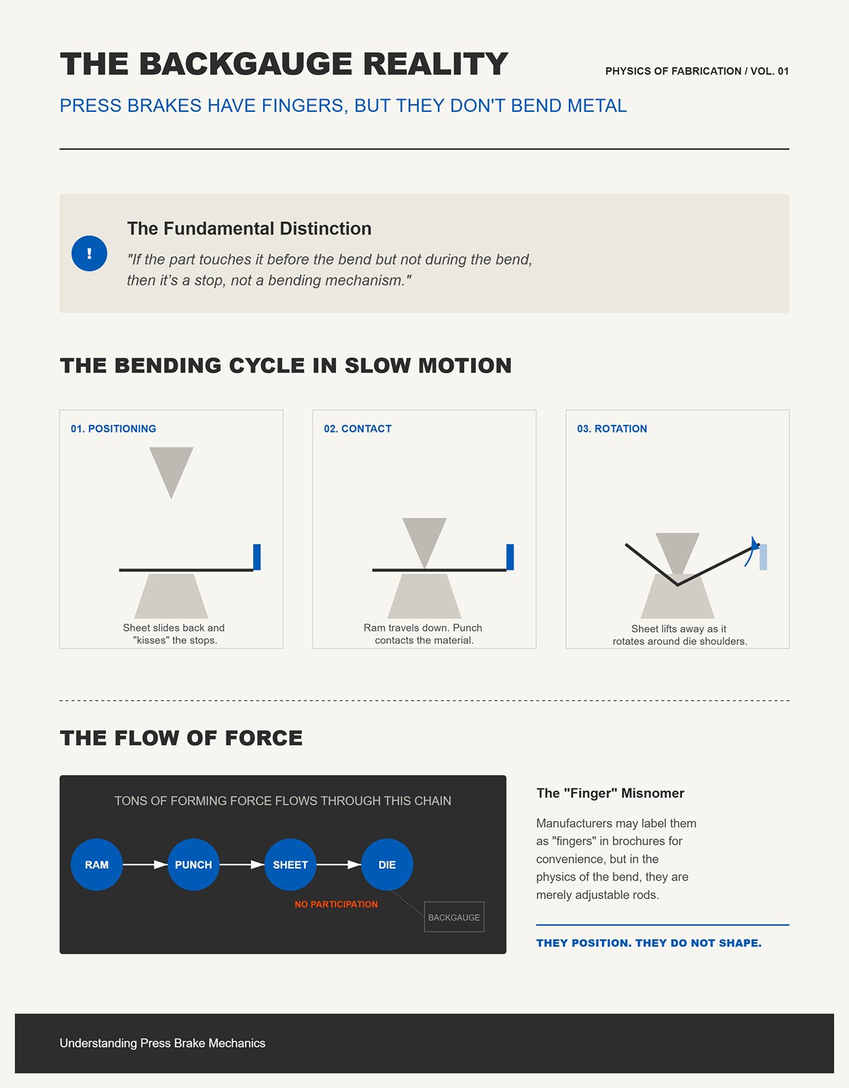
If the part touches it before the bend but not during the bend, then it’s a stop, not a bending mechanism.
Watch a press brake cycle in slow motion. The sheet slides back, kisses the stops, and the ram travels down. As soon as the punch contacts the material, the sheet lifts away from those stops because the metal is rotating around the die shoulders. The forming force—tons of it—flows from ram to punch to sheet to die. The backgauge assembly just sits there behind the action.
Yes, some manufacturers casually label those adjustable rods as “fingers.” I’ve heard it. I’ve corrected it. Call them whatever you like on a brochure; in the physics of the bend, they don’t participate.
If they’re not shaping the metal, why do people swear the machine “has fingers”?
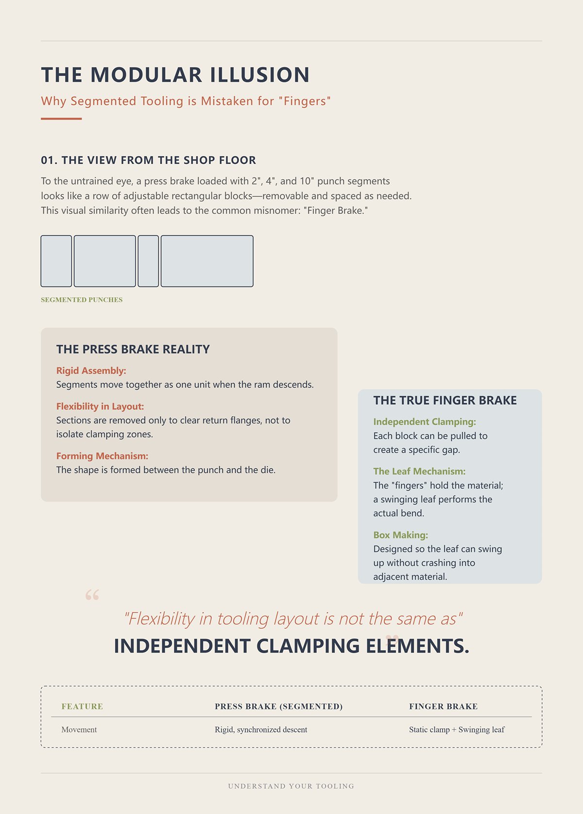
If you look at segmented tooling from across the shop, then you can see how the confusion starts.
Picture a press brake upper beam loaded with 2‑inch, 4‑inch, and 10‑inch punch segments lined up side by side. To the untrained eye, they look like a row of rectangular blocks—removable, adjustable, spaced as needed. I’ve had customers point at that and say, “See? Finger brake.”
But those segments are punches. They move together as one rigid assembly when the ram descends. You can remove a section to clear a return flange, sure. That’s flexibility in tooling layout, not independent clamping elements. On a true finger brake, each clamping block can be pulled to create a gap so the leaf can swing up and form a box side without crashing into adjacent material. The blocks are the clamping mechanism; the leaf is the bending arm.
On a press brake, the clamp is the ram, and the forming happens between punch and die. The segments don’t swing. They don’t isolate clamping zones. They just shape where the punch exists along the beam.
When you blur that distinction, what kind of mistake are you setting yourself up for?
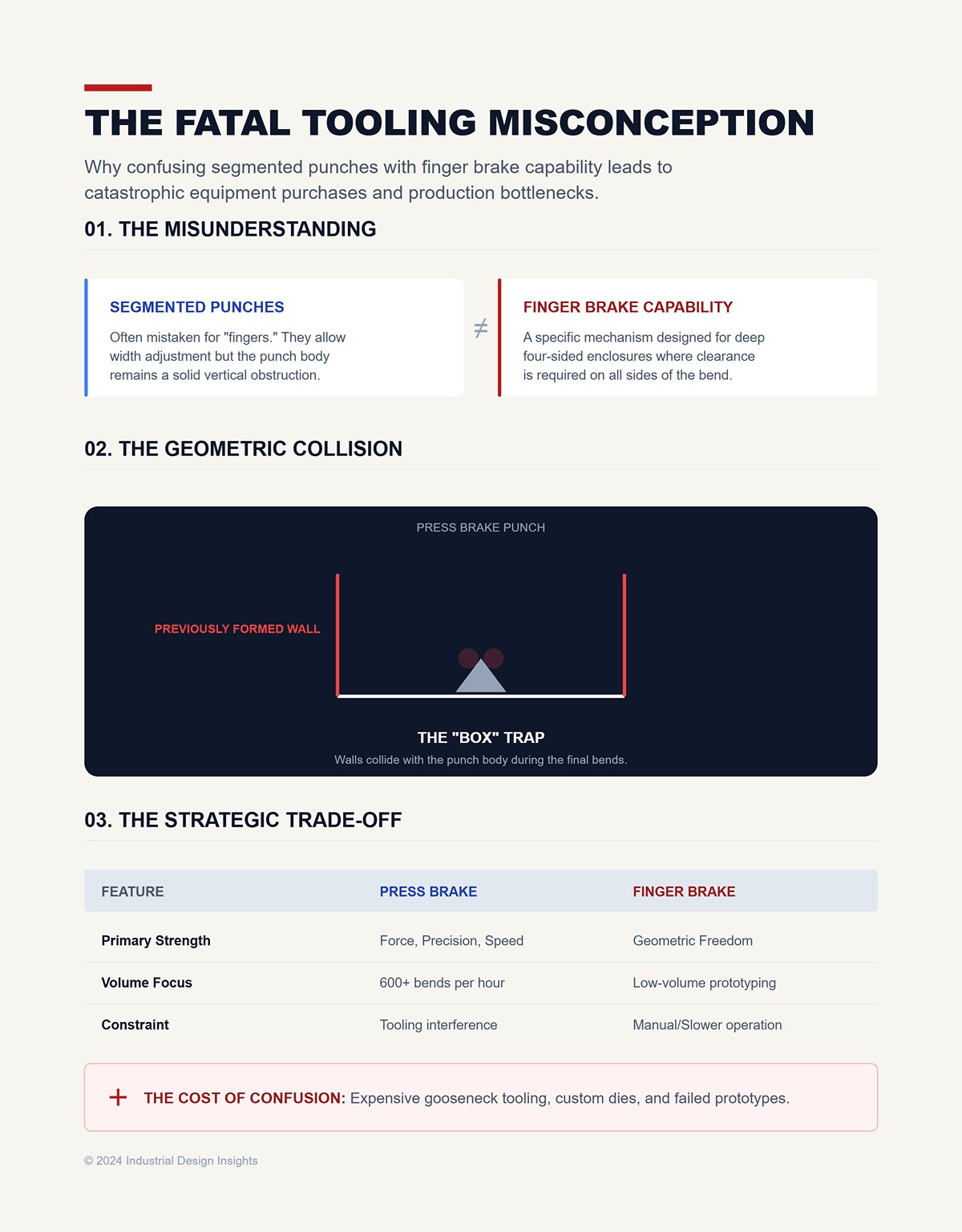
If you think segmented punches equal finger brake capability, then you’ll try to form a deep four‑sided enclosure on a press brake and wonder why the walls collide with the tooling.
I’ve watched it happen. A shop buys a fast CNC press brake—600 bends an hour, no problem—and assumes the “fingers” mean it can handle tight box work the same way a finger brake can. First prototype hits the die, second flange comes up, and the previously formed wall smashes into the punch body. Now they’re talking about custom gooseneck tooling, special dies, workarounds. Expensive ones.
A finger brake trades speed and repeatability for geometric freedom. A press brake trades geometric freedom for force, precision, and throughput. Confuse the bending mechanism with the material stop, and you confuse those trade‑offs.
And if the blocks that actually move during bending matter this much, what happens when they’re the clamping system itself?
You asked what happens when the clamping blocks themselves are the moving elements in the bend.
Picture a 48-inch box and pan brake on a job site. The sheet slides under a segmented clamping bar. The operator pulls down a handle, and a row of rectangular steel blocks presses the material tight against the bed. Then the lower leaf—one long hinged plate—swings upward and wipes the exposed edge of the sheet past 90 degrees. The clamping bar doesn’t plunge. The punch doesn’t descend. The leaf rotates.
That’s the whole trick.
If the machine bends by rotation instead of penetration, then the force path changes completely. On a press brake, the ram drives a punch into a die and the material yields in a concentrated V. On a box and pan brake, the sheet is pinched along the entire bend line and the leaf applies torque along that same line. It’s a distributed load, not a localized one. The metal is being wiped around a pivot, not forced into a cavity.
And the clamping blocks? They are the bending reference. They hold everything that must not move while the leaf moves everything that must.
Like grabbing the wrong wrench off the cart, a press brake looks close enough until you realize mid-bend that nothing on it swings—everything plunges.
So why bother breaking that clamping bar into pieces at all?
I had a small HVAC shop bring me a five-sided duct transition once—bottom, four walls, no top. They’d bent three sides and couldn’t figure out how to close the fourth without collision. On a press brake, you fight that geometry with staged tooling and careful sequencing. On a box and pan brake, you pull out two clamping segments where the sidewalls will sit, slide the part under the remaining blocks, clamp only the flat you’re about to bend, and swing the leaf. The formed walls sit up in the empty spaces.
If you need clearance for return flanges, then you must create physical voids in the clamping bar. That’s why the segments exist. Not for adjustability. For absence.
Each block is removable so pre-formed walls can occupy that space while the next flange is wiped up. The segmented clamping bar is the whole reason the machine exists. Without it, the first return flange you make would block the second. The geometry would lock you out of your own part.
This is where the myth gets twisted. Yes, you can load a press brake with 2-inch and 4-inch punch segments and leave gaps between them. Shops on the forums argue about bending 12-gauge over four feet that way. And for shallow forms, with careful sequencing, you can fake some of the flexibility. But those punch segments still move together with the ram. They don’t selectively clamp. They don’t create independent hold-down zones. They just remove steel from the punch line.
If the clamping system can’t isolate one flange while clearing another, then you don’t have the same geometric freedom—no matter how modular the tooling looks from across the shop.
That freedom comes at a price.
Stand in front of a manual 16-gauge box and pan brake and try to bend 10-gauge mild steel full width. You’ll feel the handle fight back halfway through the pull. The leaf flexes. The clamping bar starts to lift at the center. The bend line rounds because the pressure isn’t high enough to keep the material tight to the nose.
If the machine relies on distributed clamping and human-applied leverage, then thickness becomes the enemy fast.
The physics are simple. To plastically deform thicker steel, you need higher bending moment. In a press brake, you add tonnage—hydraulics don’t get tired. In a box and pan brake, the torque comes through a hinge and a long handle. The clamping bar must resist that torque across its full width. As thickness increases, required clamping force rises to prevent slip. The frame deflects. The leaf deflects. The bend angle varies across the length.
Most manual box and pan brakes top out around 16-gauge mild steel at full width; heavier gauges are possible only over shorter lengths. That’s not a marketing limitation. That’s beam deflection and leverage.
Two weeks later he was asking why it couldn’t form a deep electrical enclosure without crushing the sidewalls. The answer wasn’t hidden in a brochure. It was hiding in the mechanism. A box and pan brake gives you clearance because it spreads force and wipes. A press brake gives you power because it concentrates force and plunges.
If you need deep, multi-sided geometry in light gauge, the true “finger” machine earns its keep. If you need thickness, precision, and repeatable tonnage, the industry evolved toward punch and die for a reason.
So when the clamping blocks are the system doing the holding—and the leaf is doing the bending—you gain clearance and lose muscle.
And that trade-off is exactly why the two machines exist side by side instead of one replacing the other.
You’re standing in front of a print for a 14-gauge mild steel chassis, 36 inches wide, four sides at 3 inches tall. One machine in the shop tops out at 16-gauge full width but has segmented clamping blocks. The other is a 135-ton hydraulic press brake with a standard V-die set and programmable backgauge stops. Which one do you roll the cart toward?
If the part demands force beyond what a hinged leaf and clamping bar can physically resist, then the decision was made the day you read the material thickness.
The reason isn’t branding. It’s mechanics.
First prototype hits the die, second flange comes up, and the previously formed wall smashes into the punch body. I’ve watched it happen more times than I care to admit. The operator swears the machine “has fingers.” He means segmented punches. He’s confusing missing steel with missing geometry.
A press brake doesn’t clamp along the bend line and wipe the sheet around a pivot. It drives a punch into a V-shaped die opening. In air bending—meaning the punch never bottoms out in the die—the sheet contacts at three points: punch tip and two die shoulders. That three-point contact creates a lever. Change the punch depth by a few thousandths, and the angle changes. You’re not wrapping metal around a nose; you’re controlling penetration depth under load.
That’s why air bending can hit 90 degrees with far less tonnage than bottoming or coining. You’re not forcing the material to conform fully to the die angle. You’re letting springback happen and compensating with calculated overbend. Less force, more flexibility in angle, same tooling.
But here’s the catch nobody talks about on the sales floor.
On older hydro-mechanical brakes—pre-CNC, pump-down systems—the ram weight and hydraulic thrust weren’t always consistent enough for small parts. Air bending would drift because a few thousandths variation in material thickness or tensile strength meant a different springback. Angle variation wasn’t a mystery. It was physics. Shops bottomed parts not because air bending didn’t exist, but because the control over tonnage and position wasn’t tight enough to trust it.
If your forming method depends on continuous, precisely metered force instead of physical clamping blocks locking the sheet in place, then material variability becomes part of your accuracy equation.
That’s the trade. A finger brake gets repeatability from mechanical constraint. A press brake gets versatility from controlled force.
So what are you really paying for when you buy that 135-ton machine?
I had a buyer once justify a big brake by pointing at the segmented punch set. “It’s flexible,” he said. “We can pull sections out.” He kept saying, “But it has fingers.”
No. It had modular tooling.
If you mostly bend 20-gauge duct and light pans under 48 inches, a 135-ton brake is muscle you’ll never use. Air bending 20-gauge mild steel over a 1-inch V opening might take a fraction of the machine’s rated capacity per foot. The rest of that tonnage rating is idle iron and hydraulic overhead. You paid for cylinders, frame stiffness, and control systems designed to move thicker plate.
That sounds wasteful until the job changes.
The day a 10-gauge bracket shows up at 36 inches long, a manual box and pan brake is done before you start. The required bending moment climbs fast with thickness—exponentially compared to light gauge. On a press brake, you change the V-die width, calculate tonnage per foot, and step on the pedal. Hydraulics don’t argue. Frames built for tonnage don’t hinge and flex like a leaf brake.
If your work mix swings between thin and thick, then paying for tonnage isn’t overkill. It’s insurance.
But insurance has exclusions.
Because all that controlled force still happens between a punch and die that move as a single descending mass. Nothing on that ram selectively clamps one flange while clearing another. The backgauge stops position the part; they do not hold down isolated zones like segmented clamping blocks.
So what happens when the geometry closes in on itself?
| Section | Content |
|---|---|
| Tooling Cost vs. Versatility | Are you paying for tonnage you don’t actually need? |
| Buyer’s Justification | A buyer once justified purchasing a large brake by pointing to the segmented punch set, claiming it was flexible because sections could be removed. He kept saying, “But it has fingers.” In reality, it had modular tooling. |
| Overcapacity for Light Work | If most work involves bending 20-gauge duct and light pans under 48 inches, a 135-ton brake provides unused capacity. Air bending 20-gauge mild steel over a 1-inch V opening uses only a fraction of the machine’s rated tonnage per foot. The remaining capacity represents idle iron and hydraulic overhead designed for thicker plate. |
| When Capacity Becomes Necessary | The situation changes when a 36-inch-long 10-gauge bracket appears. A manual box and pan brake cannot handle it. Bending force requirements increase rapidly with thickness. On a press brake, you adjust the V-die width, calculate tonnage per foot, and operate. Hydraulics and rigid frames handle the load without flexing like a leaf brake. |
| Insurance Argument | If your workload alternates between thin and thick materials, paying for higher tonnage is not excess—it is insurance. |
| Limitations of Force | However, that controlled force occurs between a punch and die moving as a single descending mass. The ram cannot selectively clamp one flange while clearing another. Backgauges position the part but do not isolate and hold specific zones like segmented clamping blocks. |
| Geometric Constraints | Challenges arise when part geometry closes in on itself, limiting what the press brake can physically accomplish. |
Take a deep electrical enclosure: four walls at 6 inches tall, return flanges at the top, 14-gauge steel. Bend the first side—no problem. Second side—watch your punch clearance. Third side—you’re threading a box around a tool that only moves vertically.
By the fourth flange, you’re fighting collision, not tonnage.
Standard straight punches and V-dies assume open geometry. The ram descends in a straight line. Any previously formed wall rises with the part. If that wall extends higher than the daylight between punch shoulders or interferes with the punch body, you’re stuck. You can sequence bends, use gooseneck punches for clearance, even flip and re-reference off the backgauge stops—but you are always working around a tool that plunges, never one that creates voids along the clamp line.
A box and pan brake solves that by subtraction. Remove two clamping segments, slide the formed walls into those empty spaces, clamp only the flat you’re bending, and wipe. The clearance is built into the clamping system itself.
If the job is deep, multi-sided, and light gauge, then the segmented clamping blocks are geometry tools, not power tools.
A press brake evolved past clamping blocks because industry needed force, programmability, and angle control that scaled with thickness. It did not evolve to replace the voids those blocks create. It replaced distributed torque with concentrated tonnage.
Bring the wrong wrench to the job and you won’t notice until the bolt rounds off halfway through.
So before you ask whether the machine “has fingers,” ask something simpler: does this part fail from lack of force, or from lack of clearance?
A 10-gauge enclosure, 12 inches deep, four sides up, 1-inch return flanges on top. I watched a shop try it on a 175-ton press brake with a tall gooseneck punch. First two bends were clean. Third bend needed the box tipped and re-referenced off the backgauge stops. On the fourth, the sidewall kissed the punch body before the angle hit 70 degrees. Plenty of tonnage left. Zero clearance left.
That’s the moment the argument stops being theoretical.
When a job demands both high tonnage and deep, closed geometry, you don’t ask which machine is stronger. You ask which one can physically finish the fourth bend without trapping the part between tool steel and its own walls. If the enclosure walls grow taller than the vertical window around your punch, then force becomes irrelevant. Steel doesn’t care how big the cylinders are if the geometry locks you out.
So how does that lockout actually happen?
Set up a simple four-sided box in your head. First bend lifts one wall. Second bend lifts another. By the third, you’re feeding a U-shaped channel around a punch that only moves straight down. The previously formed walls rise with every stroke because the ram doesn’t make space—it intrudes into it.
Now add a 1-inch return flange at the top of each wall. That return shortens the effective throat depth available for the punch body. Even a gooseneck profile—designed for clearance—has a spine. Once the wall height plus return flange exceeds that spine’s offset, the punch body becomes the obstruction.
I’ve seen operators try three workarounds.
First: air bend with a narrow V-die to reduce required penetration depth. That helps angle control, but the wall height relative to punch geometry doesn’t change. The collision point just happens a few degrees later.
Second: bottom bend to force the angle in a single controlled hit. Yes, bottoming pushes the material fully into the die angle, improving repeatability. It also increases contact area and risk. If the sidewall is already grazing the punch body, bottoming just means you hit harder when it binds. Parts get scarred. Tooling gets chipped. I’ve replaced both.
Third: stacked tooling to raise the work above the lower beam and gain daylight. That works—until you run out of ram stroke or introduce instability from excessive stack height. Tall tool stacks behave like a column under load. Deflection shows up in angle variation across the length.
This is the deep enclosure test: can you complete all bends without the formed geometry colliding with the punch body during the final stroke?
A box and pan brake answers that differently. You remove clamping segments where the walls need to occupy space. The sheet is clamped only along the active bend line, and the leaf rotates to wipe the flange up. The formed walls sit in the voids you created before the bend starts. Clearance isn’t something you fight for mid-stroke; it’s designed in before you pull the handle.
One machine intrudes vertically into a shrinking cavity. The other rotates around open air.
If the fourth bend traps the tool, no amount of tonnage rescues the wrong machine.
But maybe you’re thinking: fine, the finger brake wins on geometry. What if I only need ten boxes a month?
Picture a short run—eight deep enclosures, 14-gauge, 8 inches tall, no returns. On a press brake, you’re selecting a gooseneck punch, matching die height, checking that bottom tool holder plus die plus punch still leaves stroke in reserve. You dry-cycle with a scrap blank to confirm wall clearance. Maybe you shim for parallelism if you stacked tooling.
That’s not theory. That’s an hour gone before first good part.
Cycle time per bend on a CNC press brake is quick once dialed in. Backgauge stops move automatically. Angle correction is programmable. For fifty parts, that setup cost spreads out and makes sense.
Now move to a manual box and pan brake. You pull the clamping blocks you don’t need, slide the blank in, set your bend depth stop, and go. Setup is physical, not computational. For low volumes, especially when wall heights are well within the machine’s rated capacity, the simplicity shows. No tool stack math. No ram stroke budgeting.
But capacity is the wall you eventually hit. A manual finger brake rated for 16-gauge mild steel across full width will not politely stretch to 10-gauge just because you have only eight parts. The bending moment rises with thickness, and the clamping bar will deflect before the material yields uniformly. You get inconsistent angles and a machine that ages ten years in a week.
So low volume doesn’t automatically favor the simpler machine. It favors the machine whose capacity envelope actually contains your part.
If the geometry demands voids and the thickness demands force, you’re standing between two partial answers. Which compromise hurts less?
I’ve run segmented press brake tooling—modular punch sections you can remove to create localized clearance. He kept saying, “But it has fingers.” No. It had segmented punches and adjustable backgauge stops. The clamping mechanism never changed.
Here’s what happens in practice.
You pull out punch sections where sidewalls need space. That creates a horizontal gap in the punch line. Good. But the ram still descends as a single beam. The remaining punch sections must carry the full tonnage across their engaged length. Stress concentrates at the shoulders of the active segments. For thick material, that means higher localized load and potential deflection at the transition between loaded and unloaded zones.
You also lose continuous support along the bend line. On deep boxes, that can translate into slight angle variation near the segment edges unless your tooling and crowning are dialed in perfectly. It’s workable. It’s not magic.
Contrast that with a true box and pan brake: the clamping blocks apply distributed pressure only where needed, and the leaf provides uniform rotational motion along the entire bend length. There’s no descending mass threading between walls. The geometry is resolved before force is applied.
Segmented press brake tooling is a compromise. It can extend the geometric reach of a brake, especially with moderate wall heights and careful sequencing. I’ve seen a 10.5-inch-deep box formed successfully this way with stacked clamps and a 3-inch punch. It worked because the punch profile, die height, and box depth were all in a narrow compatibility window.
Miss that window by an inch of wall height or a gauge of thickness, and you’re back to interference or overload.
So here’s the decision point I ask buyers now: draw the tallest wall of your deepest enclosure. Add any return flange. Measure from bend line to the highest obstruction during the final bend. Then compare that to the true vertical and horizontal clearance of your punch profile under load.
If the numbers don’t fit on paper, they won’t fit under 150 tons.
That’s the deep enclosure test. Pass it, and a press brake earns its keep. Fail it, and no one on the floor cares what the brochure called the tooling.
If both wall height and material thickness are flirting with the red line, then you don’t pick the machine with the bigger number on the nameplate — you pick the one whose failure mode you can live with.
I’ve watched buyers freeze right there. Geometry says one thing. Tonnage chart says another. They want a tie‑breaker. Here it is: ask which limit fails gracefully in production and which one wrecks parts mid‑run. A press brake that runs out of geometric clearance doesn’t warn you with a softer angle. It collides. A finger brake that runs out of stiffness starts telegraphing the problem — angle drift, clamp deflection, more effort at the handle. One ruins tooling. The other ruins consistency.
That difference is not academic.
When a press brake loses the geometry fight on a deep enclosure, it does it on the fourth bend, after you’ve already invested time in the first three. First prototype hits the die, second flange comes up, and the previously formed wall smashes into the punch body. Now you’re rethinking tooling stacks and sequencing while the clock runs. When a finger brake is overmatched on thickness, the struggle shows up on bend one. You feel it in the handle. The clamping bar flexes. You stop before you’ve built scrap inventory.
Which failure would you rather discover at part one instead of part twenty?
That’s how you judge risk when both limits are tight: not by maximum capacity, but by how early the machine tells you you’re wrong.
If you’re still asking whether a press brake “has fingers,” then you’re shopping by appearance instead of motion.
He kept saying, “But it has fingers.” No. It had segmented punches and adjustable backgauge stops. The ram still drove a punch straight down into a narrowing cavity. The clamping blocks on a true finger brake move out of the way before the bend ever starts. One design creates voids ahead of time. The other tries to survive inside them.
That’s not a naming issue. That’s kinematics — the study of motion.
The better buying question is simple and brutal: what shape exists in space during my last bend? Draw it. Include returns. Include hems. Then ask whether the tool moves around that space or into it. Bringing the wrong wrench to the job feels fine until the bolt head rounds off halfway through the pull. A segmented punch might look close enough to a finger brake in a brochure. Mid‑stroke, it proves otherwise.
Now the real shift happens.
Stop listing features. Start mapping geometry at scale. How many enclosures per week? How tall are the walls? Are returns standard or occasional? Because once you think in terms of “void management” instead of “does it have fingers,” you stop being impressed by hybrid marketing terms and start seeing motion paths.
And when geometry is fixed by your product, what exactly are you scaling — shape complexity or bend count?
If your prototypes demand aggressive geometry but your production demand is light, then a finger brake can be the right answer — until you confuse prototype speed with production capacity.
A box and pan brake can be set up in minutes for a new enclosure. Pull clamping blocks, slide sheet, wipe the bend. For custom runs and engineering churn, that speed matters more than raw tonnage. Setup time beats cycle time when quantities are low and shapes keep changing.
But scale changes the math.
Manual finger brakes slow down as parts get wider and heavier. Over four feet, you’re often at two operators. After twenty or thirty bends, fatigue creeps in and angle consistency drifts. Meanwhile, a CNC press brake with programmable backgauge stops will hammer out 600 bends an hour once dialed in. Same angle. Same depth. No argument.
So here’s the non‑obvious part.
You don’t choose the machine that scales “more.” You choose the machine that scales the constraint that defines your product. If your business is deep, complex enclosures in modest volumes, scaling geometric flexibility matters more than bend-per-hour bragging rights. If your parts are shallow but thick and repetitive, scaling force and repeatability wins.
When both thickness and wall height sit near the edge, decide which compromise hits your revenue model harder: slower labor with guaranteed clearance, or faster automation that risks geometric disqualification. One limits throughput. The other can disqualify the part entirely.
Carry this forward: machines don’t compete on features. They compete on which physical constraint they remove from your business model.
Once you see that, you stop asking about “press brake fingers” — and start asking which constraint you can afford to live with.


