

I watched a 1-inch AR400 plate split with a sound like a rifle shot.
We were on a 250-ton mechanical brake. Flywheel spinning. Clutch engaged. Ram dropped. The operator treated it like every other bend he’d ever made—set the backgauge, hit the pedal, let the machine do its thing. The punch hit hard, bottomed fast, and the plate didn’t yield evenly. It fractured along the inside radius. Six thousand dollars of steel turned into scrap in under two seconds.
He kept saying, “But it’s rated for the tonnage.”
That’s the sentence that gets people hurt.
You’ve probably been told a press brake is just a metal folder with more muscle. Line it up. Hit it. Bend it. Repeat.
That works fine when you’re folding 11-gauge mild steel all day.
But the moment you move into high-strength plate—AR400, Hardox, quenched-and-tempered structural—you’re not folding paper anymore. You’re forcing a material with low ductility and high yield strength to deform without cracking. That’s not a “hit it and hope” operation. That’s controlled plastic deformation under load.
Different machines deliver that load in completely different ways. Some strike. Some push. Some squeeze and let you feel what’s happening mid-stroke.
If you treat them all like kinetic hammers, you’re gambling expensive plate on a force curve you don’t even understand.
So what actually happens inside each type of brake when the ram starts down?
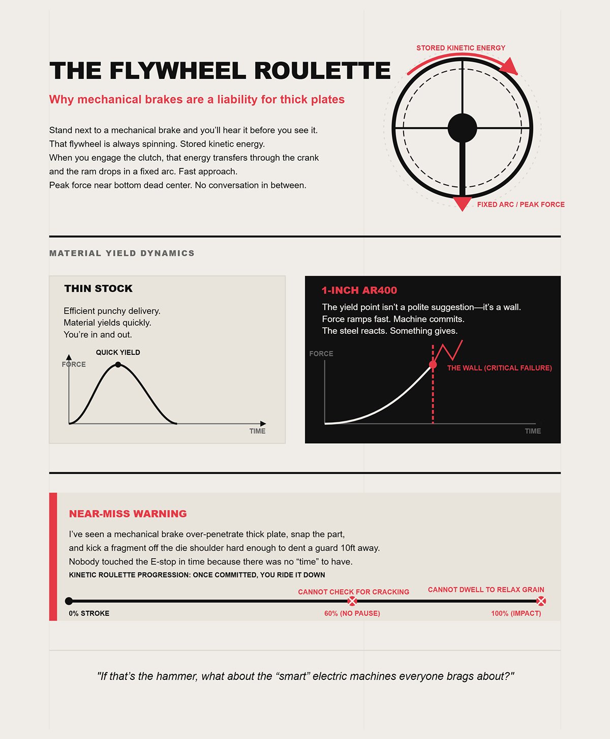
Stand next to a mechanical brake and you’ll hear it before you see it. That flywheel is always spinning. Stored kinetic energy. When you engage the clutch, that energy transfers through the crank and the ram drops in a fixed arc. Fast approach. Peak force near bottom dead center. No conversation in between.
On thin stock, that punchy delivery is efficient. The material yields quickly. You’re in and out.
On 1-inch AR400, the yield point isn’t a polite suggestion—it’s a wall. When the ram hits, the force ramps fast. If your die opening is slightly off, or your inside radius is too tight, you don’t get a chance to ease into the bend. The machine commits. The steel reacts. Something gives.
Near-Miss Warning: I’ve seen a mechanical brake over-penetrate thick plate, snap the part, and kick a fragment off the die shoulder hard enough to dent a guard ten feet away. Nobody touched the E-stop in time because there was no “time” to have.
With a mechanical, once the ram is committed, you’re riding it down. You can’t pause at 60% stroke and check for cracking. You can’t dwell under load to let the grain structure relax. It’s kinetic roulette.
If that’s the hammer, what about the “smart” electric machines everyone brags about?
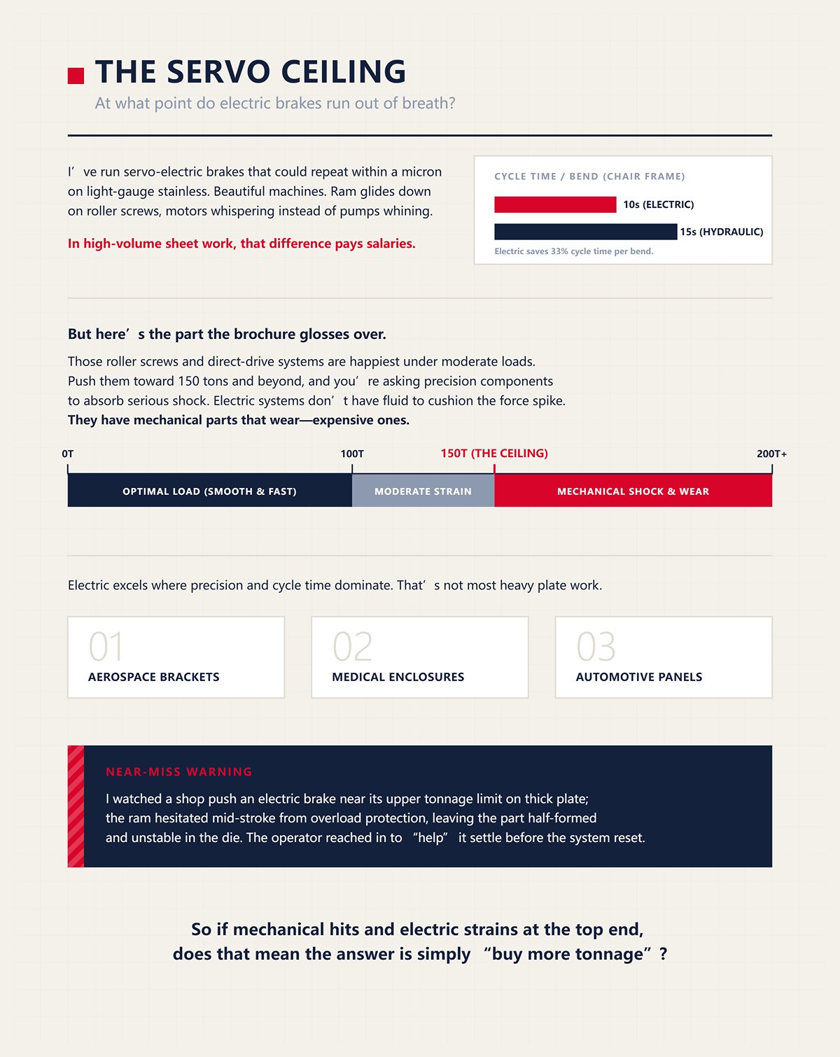
I’ve run servo-electric brakes that could repeat within a micron on light-gauge stainless. Beautiful machines. Ram glides down on roller screws, motors whispering instead of pumps whining. Bend a chair frame in ten seconds. Hydraulic next to it takes fifteen. In high-volume sheet work, that difference pays salaries.
But here’s the part the brochure glosses over.
Those roller screws and direct-drive systems are happiest under moderate loads. Push them toward 150 tons and beyond, and you’re asking precision components to absorb serious shock. Electric systems don’t have fluid to cushion the force spike. They have mechanical parts that wear—expensive ones.
You can absolutely bend structural steel on an electric brake within its rating. But as thickness climbs and tonnage rises, the machine’s advantage—speed and repeatability—stops being the whole story. You’re now limited by how much sustained load the drive system can take without accelerating wear or losing that silky control you paid for.
Near-Miss Warning: I watched a shop push an electric brake near its upper tonnage limit on thick plate; the ram hesitated mid-stroke from overload protection, leaving the part half-formed and unstable in the die. The operator reached in to “help” it settle before the system reset.
Electric excels where precision and cycle time dominate. Aerospace brackets. Medical enclosures. Automotive panels. That’s not most heavy plate work.
So if mechanical hits and electric strains at the top end, does that mean the answer is simply “buy more tonnage”?
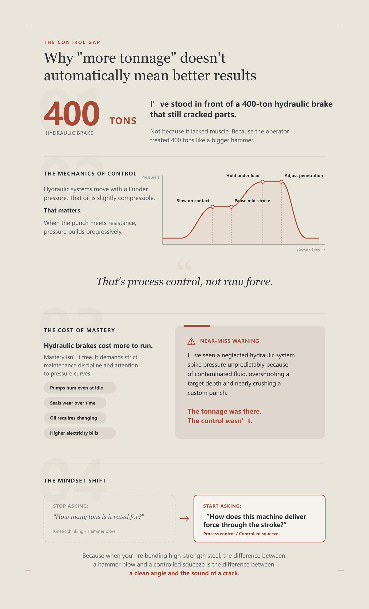
I’ve stood in front of a 400-ton hydraulic brake that still cracked parts.
Not because it lacked muscle. Because the operator treated 400 tons like a bigger hammer.
Hydraulic systems move with oil under pressure. That oil is slightly compressible. That matters. When the punch meets resistance, pressure builds progressively. You can slow the ram as it contacts the material. You can pause mid-stroke. You can hold under load and watch the bend develop. You can adjust penetration to manage springback—the elastic recovery that tries to open your angle after release.
That’s process control, not raw force.
And here’s the part most new hires miss: hydraulic brakes cost more to run. Pumps hum even at idle. Seals wear. Oil needs changing. Electricity bills run higher than electric machines that power down between cycles. Mastery isn’t free. It demands maintenance discipline and attention to pressure curves.
Near-Miss Warning: I’ve seen a neglected hydraulic system spike pressure unpredictably because of contaminated fluid, overshooting a target depth and nearly crushing a custom punch. The tonnage was there. The control wasn’t.
More tonnage only helps if you can meter it. If you can’t pause, hold, and feel what the material is doing, you’re back to kinetic thinking—just with a bigger number on the nameplate.
So the shift I need you to make is this: stop asking, “How many tons is it rated for?” and start asking, “How does this machine deliver force through the stroke?”
Because when you’re bending high-strength steel, the difference between a hammer blow and a controlled squeeze is the difference between a clean angle and the sound of a crack.
We were bending 1-inch AR400 in a 12x die opening, target 90 degrees. The gauge climbed past 350 tons as the punch started to bite. At about 60% of final depth, I saw the inside edge whitening—first sign the grain was stretching hard. I hit the pause. Ram stopped. Pressure held at 380 tons. Plate stayed clamped between punch and die like it was frozen in time.
That right there is how you decide which brake belongs under your steel.
If you can’t stop under load, you can’t interrogate the bend while it’s happening. And if you can’t interrogate it, you’re guessing whether that 1-inch plate wants 420 tons—or wants to split at 401. High-strength steel doesn’t forgive guessing.
Hydraulics let you turn force into something you can meter, not just unleash.
Stand at the control and Stop the ram at first contact with full resistance. Don’t wait for bottom. Watch the pressure rise as the material transitions from elastic to plastic deformation. That change isn’t theoretical—you’ll see the tonnage climb faster once the steel yields.
In HSLA or AR plate, yield strength is high and springback runs 8 to 10 degrees if you don’t manage it. The mid-stroke pause lets you hold pressure and let the material flow instead of shocking it. Steel under load redistributes stress along the bend line. Give it a second. You can literally see the angle relax a hair before you continue.
Try that on a mechanical. You can’t.
But here’s the part the brochure glosses over: pause only protects you if the setup is correct. If you’re using a V-die under 6x material thickness on high-strength steel, you’re concentrating force so tightly that thinning can hit double digits at the inside radius. You pause—and all you’ve done is hold maximum stress exactly where a crack wants to start.
Near-Miss Warning: I watched an operator pause a 3/4-inch HSLA bend in a too-narrow die. He thought stopping meant safe. The plate split while stationary under 300-plus tons, and the release snapped the offcut upward like a sprung trap.
Pause is a safety asset. It is not a substitute for correct die width and preheat when required. So if you can stop the ram, what are you really controlling—the stroke, or the force itself?
On a hydraulic brake, Dial the pressure limit before you ever cycle down. Set a ceiling below the machine’s maximum rating. That ceiling becomes your guardrail.
Hydraulic systems build pressure progressively. Oil compresses slightly; valves meter flow; cylinders convert pressure into linear force. As resistance increases, pressure rises smoothly along a curve you can watch in real time. You are riding a river of force, not firing a shot.
Mechanical and even servo-electric systems deliver force tied to motion profiles and stored or transmitted mechanical energy. Once the ram is committed near bottom dead center, peak force arrives whether the steel likes it or not. That’s impact behavior, even if it’s precise impact.
Does “infinite control” mean hydraulics can bend anything? No. Once you’re north of roughly 50 mm plate thickness, most standard hydraulic brakes are at their structural and pump limits. You’ll need tandem setups or specialized equipment. And on thin sheet, electrics often beat hydraulics for repeatability and energy use.
So why does hydraulic dominate high-strength plate?
Because fracture in AR or HSLA isn’t about average tonnage. It’s about spike control. Micro-cracks start when local stress exceeds tensile limits at the inside radius. A smooth pressure ramp reduces instantaneous overstress. A fixed impact doesn’t care about your grain structure.
Near-Miss Warning: We once tested a new batch of AR plate without adjusting the pressure ramp. The ram hit fast approach speed too long before decelerating. The pressure spiked 40 tons above our usual curve in a fraction of a second. The crack sounded like a rifle shot.
If you can shape the force curve, you reduce spike risk. If you can’t, you’re betting the steel behaves exactly like the last batch. And that leads to the question most new hires never ask: what’s actually happening inside that cylinder when you hold 400 tons and the ram just… waits?
| Topic | Details |
|---|---|
| Infinite Tonnage Control vs. Fixed Impact | Preventing material fractures |
| Hydraulic Brake Setup | Dial the pressure limit before cycling down. Set a ceiling below the machine’s maximum rating to create a safety guardrail. |
| How Hydraulic Systems Apply Force | Pressure builds progressively. Oil compresses slightly; valves meter flow; cylinders convert pressure into linear force. As resistance increases, pressure rises smoothly along a visible real-time curve—like riding a river of force, not firing a shot. |
| Mechanical & Servo-Electric Systems | Force is tied to motion profiles and stored/transmitted mechanical energy. Near bottom dead center, peak force arrives once committed—regardless of material response. This is impact behavior, even if precisely controlled. |
| Limits of “Infinite Control” | Hydraulics cannot bend everything. Above ~50 mm plate thickness, most standard hydraulic brakes reach structural and pump limits, requiring tandem or specialized setups. For thin sheet, electric systems often outperform hydraulics in repeatability and energy efficiency. |
| Why Hydraulics Dominate High-Strength Plate | Fracture in AR or HSLA steel depends on spike control, not average tonnage. Micro-cracks form when local stress exceeds tensile limits at the inside radius. A smooth pressure ramp reduces instantaneous overstress; fixed impact does not account for grain structure. |
| Near-Miss Warning Example | During testing of a new AR plate batch, failure to adjust the pressure ramp caused the ram to decelerate too late. Pressure spiked 40 tons above the normal curve in a fraction of a second, resulting in a crack that sounded like a rifle shot. |
| Key Insight | Shaping the force curve reduces spike risk. Without control, you rely on the steel behaving exactly like the last batch—raising the question of what happens inside the cylinder when holding 400 tons and the ram simply waits. |
Picture two large cylinders filled with oil, sealed tight, pistons pushing downward. Increase pump flow and watch pressure climb as the punch meets resistance. The oil molecules compress slightly—just enough to act like a stiff spring. Control valves restrict or allow flow, which changes how fast pressure builds.
When you pause mid-stroke, the valves close. Flow stops. Pressure equalizes across the fluid column. The oil holds the pistons in position because there’s nowhere for it to go. You are storing energy as hydraulic pressure, not as spinning mass or stretched mechanical components.
That’s the difference.
A flywheel stores energy kinetically. A roller screw stores it mechanically. Hydraulic oil stores it as controlled pressure. Release the valve slowly and the force bleeds off smoothly. Dump it fast and you’ll see a sharper reaction—but still governed by fluid flow, not inertia alone.
And here’s the practical part: contaminated oil, worn seals, or sticky proportional valves distort that pressure curve. Your “smooth river” turns turbulent. That’s when hydraulics lose their advantage.
Near-Miss Warning: A clogged return filter once caused pressure lag on a heavy bend. The operator compensated by commanding more depth. When the valve finally responded, the ram over-penetrated and nearly crushed a segmented die set.
Fluid dynamics is your defense—but only if the fluid system is healthy and the setup is correct.
So now you know why hydraulics can pause, hold, and shape force. The real question isn’t whether the machine can control tonnage. It’s whether you know how much your specific steel, thickness, die width, and temperature actually require before you ever touch the pedal.
We had a 12-foot stick of 3/8-inch plate on the bed—customer drawing said “A36.” The operator grabbed the standard chart: about 60 tons over that length in a 3-inch V. Safe. Routine. Then the mill cert showed up late. It wasn’t A36. It was AR400.
That one swap takes your nice, comfortable chart number and stretches it until your cylinders are working in a range you never planned for.
Here’s how you calculate it before you ever touch the pedal.
Start with the baseline formula for air bending mild steel:
Tonnage per foot ≈ (K × Tensile Strength × Thickness²) / Die Opening
For 60,000 PSI mild steel, most charts already bake the constant in. That’s your “1.0” material factor. Now change the steel, and you change the math.
AR400 isn’t 60,000 PSI tensile. It’s typically north of 180,000 PSI tensile with yield up around 140,000–160,000 PSI depending on batch. That means your material factor isn’t 1.0. It’s closer to 2.5 compared to mild.
So if your chart says 60 tons for that bend in A36, AR400 doesn’t need “a little more.” It needs something in the neighborhood of 150 tons for the same geometry. Same thickness. Same die. Same angle.
If you don’t multiply, you’re not underestimating by 10%. You’re off by a factor that can push you right past the hydraulic window your machine can safely hold. And that’s before we even talk about die width.
So what exactly in the steel forces you to throw away the chart?
Look at the inside radius after a bend. That’s where the outer fibers stretch and the inner fibers compress. The bend starts when you exceed yield strength, not tensile. Yield is the point where the steel stops behaving elastically and starts to flow.
Most generic tonnage charts are built around 60,000 PSI tensile mild steel. They assume a typical yield-to-tensile ratio for that grade. Swap in 304 stainless, and you’re dealing with tensile around 90,000 PSI. Swap in AR400, and both tensile and yield jump dramatically.
That matters because required bending force scales almost directly with tensile strength in the formula. Double the tensile, and for the same thickness and die opening, you’re roughly doubling required tonnage.
But here’s the part the brochure glosses over: many operators read “yield 140,000 PSI” on a cert and plug in tensile 140,000. Or worse, they ignore both and trust the mild-steel chart. That’s how you silently command 120 tons when the job really needs 280.
On a hydraulic brake, you can watch pressure climb and pause. On a mechanical, you just get the ram drop. Either way, if you calculated wrong, the machine doesn’t care about your optimism.
Near-Miss Warning: We once bent 1/2-inch stainless assuming a 1.5 material factor. The batch tested hotter than spec—closer to 100,000 PSI tensile. The operator bottomed out the stroke chasing angle. Pressure spiked past the die’s rating and cracked a shoulder. No one hurt. Expensive lesson.
So you’ve corrected for strength. Good. Now tell me—what die opening are you using, and do you know what that does to the pressure curve inside your cylinders?
Take that same 3/8-inch AR400. Say you pick a 2-inch V because you want a tighter inside radius. The tonnage formula squares thickness and divides by die opening. Cut the V in half, and you nearly double the required force.
Standard practice for mild steel air bending is about 8× material thickness for the V opening. Go narrower—6× or 4×—and tonnage climbs fast. On high-strength plate, that climb isn’t linear pain. It’s hydraulic risk.
Here’s the trap: your machine might be rated 200 tons. But that rating isn’t always full tonnage across full length. Deflection and hydraulic distribution mean you can’t just assume uniform capacity end to end. Load a long, narrow V with high-strength steel, and you concentrate force into a smaller contact area. Pressure in the cylinders rises to compensate.
If your calculated tonnage for AR400 in an 8× V was 150 tons, dropping to a 6× V can push you north of 200. You didn’t change thickness. You changed geometry—and forced the hydraulic system toward its ceiling.
And when a hydraulic cylinder hits maximum system pressure, it doesn’t politely warn you. Relief valves chatter. Seals take the load. You’re one sticky valve away from a sudden over-penetration.
Near-Miss Warning: A new hire once chose a 5× V on 1/2-inch HSLA to “get cleaner corners.” The tonnage calculation he skipped would’ve shown we needed more than the brake’s distributed capacity over 10 feet. The ram stalled, pressure pegged, and when he backed off, the part sprang violently, nearly knocking him off balance.
You can pause mid-stroke all you want. If your die choice demands more tonnage than your hydraulic system can deliver smoothly, you’re not controlling a river—you’re trying to dam a flood with a shop rag.
So maybe you say, fine, I’ll air bend in a wider die to keep tonnage down. That solves everything, right?
Air bending only contacts the punch tip and die shoulders. The material floats between. That keeps required tonnage lower—often a fraction of bottoming or coining, which can demand two to four times the force because you’re forcing the steel to conform to the die angle and radius.
For example, 3 mm mild steel over a 24 mm V might need roughly 20 tons per meter in air bending. Switch to bottoming, and you can easily double or triple that. Same sheet. Same thickness. Entirely different hydraulic demand.
On AR400, air bending keeps tonnage manageable—but springback can be 8 to 10 degrees. That tempts operators to chase angle by driving deeper, flirting with unintended bottoming. The moment you transition from air bending into bottoming without recalculating, your tonnage requirement jumps sharply.
That jump is where cylinders get surprised.
If you truly need tight tolerances on high-strength plate, sometimes controlled bottoming makes sense—but only if you calculated the higher force in advance and confirmed both machine and tooling ratings in consistent units. Metric tons per meter are not the same as short tons per foot. Mix those up, and you can think a die is three times stronger than it actually is.
If you treat them all like kinetic hammers, you’re gambling expensive plate on a force curve you don’t even understand.
Hydraulics give you the power to pause, hold, and shape force. But calculation decides whether that pause happens at 140 safe tons—or at 260 tons chewing up seals and flirting with fracture. And that leads straight to the next discipline you have to master: once you know the right tonnage, how do you sequence the ram and pressure so you actually hit it—without overshoot?
We were on a 250-ton mechanical brake when I learned this the hard way. You set the depth, hit the pedal, and the ram dropped like a guillotine. No pause. No adjustment. If you missed the angle, you lived with it.
A hydraulic brake doesn’t have to behave that way.
You’ve calculated the tonnage. You know your die opening. Good. Now the real question: how do you move 180 tons through steel without overshooting it by 20 because your valve lagged a half-second behind your foot?
You stop thinking in inches of stroke and start thinking in flow rate and pressure rise. A hydraulic brake is a river. Control the current, not just the shoreline.
Watch the pressure gauge the next time you bend 1/2-inch AR400 in an 8× V. The first two inches of travel? Barely any load. You’re just closing daylight. Then the punch kisses the plate. Pressure starts to climb—not sharply, but steadily—as elastic deformation begins. That curve tells you where your control matters.
Set a fast approach speed down to 0.200 inch above material. Move air quickly; don’t waste cycle time compressing nothing.
Reduce to a controlled pinch speed before contact. I like a noticeable drop—fast enough to stay productive, slow enough that the proportional valves can keep up. Closed-loop systems correct in milliseconds, but the valve still has a physical response time. If you’re flying at full speed into contact, the controller is reacting to yesterday’s mistake.
Here’s the mechanism: hydraulic pressure doesn’t spike because steel is evil. It spikes because fluid is nearly incompressible and your cylinders are still flowing at high rate when resistance suddenly jumps. Slow the flow before resistance rises, and the pressure ramp smooths out. You’ve shaped the force curve instead of slamming into it.
Transition into press speed as tonnage builds past 30–40% of target. This is where high-strength plate starts fighting back. Keep the ram parallel. Modern sync systems can hold ±0.01 mm per meter—but only if both cylinders see balanced flow. If one side lags because you commanded too aggressive a rate, you’re not bending; you’re twisting.
Near-Miss Warning: A new operator once left approach speed high all the way to contact on 3/4-inch HSLA. The ram hit, pressure overshot, and the right cylinder lagged 0.3 mm before correction. The part cambered, the punch chipped, and his hands were still inside the die area clearing scale when it happened. Fast strokes steal reaction time.
Program a controlled return speed too. Reverse flow isn’t an afterthought. If the upstroke rebounds too hard, you introduce ram bounce. That bounce shows up on the next cycle as inconsistent depth, and suddenly you’re chasing angle with depth tweaks that were never the real problem.
So you’ve sequenced the stroke. You’re hitting target tonnage without overshoot. Now the steel relaxes and opens up three degrees. Do you chase it deeper—or hold it where it is?
Bend a piece of 1/2-inch AR400 to 90 degrees in air. Release pressure. It opens to 97. That seven degrees is elastic recovery—stored energy leaving the steel the moment you unload it.
Most operators stab deeper on the next hit. More depth. More force. Hope for 90 on release.
Pause at bottom dead center with controlled pressure instead. Not a long coffee break—half a second to a second under stable tonnage. What happens physically? You’re allowing micro-yielding to distribute through the thickness instead of snapping back immediately. The pressure stays constant; the material’s internal stress redistributes.
But here’s the part the brochure glosses over: holding is not magic. If you’re already at 95% of machine capacity, a static hold can create thermal rise in the oil and localized stress in the die shoulders. Continuous, well-shaped pressure is safer than repeated heavy holds.
Use hold time as a fine adjustment after you’ve dialed approach and press speeds—not as a crutch for bad geometry or under-calculated tonnage.
Modern angle correction can adjust mid-stroke. It sees you’re trending shallow and commands a little more depth. The machine can do that. The judgment of when to trust it is yours. If correction demands a sudden spike near bottom, you’re better off backing up and reprogramming the pressure ramp than letting it punch harder at the worst possible moment.
Near-Miss Warning: We once chased springback on thick stainless by adding depth instead of adding 0.7 seconds of hold. The operator bottomed into the die angle unintentionally. Tonnage doubled instantly. The relief valve screamed, and the part kicked back when released, nearly catching his forearm against the backgauge.
So when does over-bending make sense? When you’ve confirmed the higher tonnage demand stays inside machine and tooling limits, and when your pressure ramp is smooth enough that you’re not shocking the system at the bottom.
Which brings up something most new hires ignore until parts start measuring different angles at the ends than in the middle.
Load 10 feet of 3/8-inch high-strength plate and push 160 tons across it. The bed will deflect. Not because it’s poorly built—because steel bends under load. The center sags a few thousandths. That means less penetration in the middle, more angle.
You can calculate tonnage perfectly and still get a smile-shaped bend.
Measure a test piece at both ends and center before touching crowning. Don’t guess.
Adjust mechanical or hydraulic crowning incrementally—just enough to counter expected deflection at your calculated tonnage. Crowning pre-loads the bed upward so that under full force it straightens out.
Here’s the mechanism: without crowning, your cylinders are delivering equal force, but the frame geometry redistributes contact pressure unevenly. The hydraulic system might be synchronized to microns, yet the structure itself is flexing. You’re controlling fluid perfectly inside a frame that’s bending like a bow.
Preventive checks matter here. Ram alignment every few hundred cycles. Clean oil so valves respond consistently. Eighty percent of valve failures trace back to contamination. Drift a few thousandths out of parallel, and your beautiful pressure profile produces inconsistent angles side to side.
Near-Miss Warning: We ignored crowning on a long HSLA run, assuming the CNC would “handle it.” Center angles came out two degrees open. The operator compensated with extra depth. Ends over-bent, center still shallow, and one part cracked along the inside radius where stress peaked.
Hydraulic precision only pays off when the structure under it is tuned and the sequence through the stroke is deliberate.
You can command 180 tons. The machine will give it to you. The real skill is deciding how fast to approach, how gently to let pressure rise, when to hold, and how much to pre-load the bed so that force moves like a steady river instead of a hammer blow.
And if the river changes temperature over a long shift—if oil thins out and response timing drifts—what happens to the sequence you so carefully programmed?
You asked what happens when the river of force warms up halfway through the shift.
Here’s what happens: your 90 in the morning becomes 92 by three o’clock, and nobody touched the program.
Hydraulic oil is not just a lubricant. It is the transmission medium between your servo valve and 180 tons of ram. When it’s cold at startup, viscosity is higher — thicker fluid, slower through the valve orifices, slightly delayed cylinder response. As the machine cycles, the oil thins. The same valve command now moves more fluid, faster. That changes how quickly pressure builds at the bottom of the stroke and how tightly the system holds tonnage during that half-second pause you carefully programmed for springback control.
The position scale may still read ±0.01 mm.
But the pressure curve that got you there has shifted.
And that means the steel feels a different squeeze.
We were on a 250-ton mechanical brake years ago, and drift meant worn linkage. On hydraulics, drift often means heat.
Start the day with 68-degree oil. Your approach speed is crisp but slightly damped; pressure ramps in with a soft shoulder. By mid-afternoon, oil temp climbs 20 or 30 degrees under heavy cycling. Viscosity drops. Servo valves react quicker. The ram may reach depth the same, but the pressure builds sooner in the last few millimeters of travel. That earlier pressure rise reduces effective hold time under stable tonnage — because the steel begins yielding under a steeper curve.
So your carefully tuned half-second hold is no longer the same half-second.
Add this: the bed warms. Thick plate warms. Even the shop air shifts between morning and afternoon. Steel’s yield strength moves slightly with temperature, and springback follows it. Now you’re not dealing with oil alone. You’re watching a whole-shop thermal cascade nudge your angle open or closed by a degree or two.
That’s not operator error.
That’s fluid behavior rewriting your sequence.
Near-Miss Warning: We once ignored rising oil temps on a long AR400 run and kept adding 0.2 mm depth to chase a creeping open angle. By hour six, oil was hot, response was sharp, and one cycle hit bottom harder than expected — pressure spiked early, the part snapped back on release, and the operator’s hand was still on the flange checking angle.
So what do you do?
Warm the machine deliberately before dialing final depth. Monitor oil temperature, not just part angle. Program pressure ramps that tolerate small response changes instead of knife-edge spikes near bottom dead center. If your machine has cooling, keep it maintained — clogged coolers turn precision systems into guesswork by noon.
You’re not fighting the steel.
You’re managing the river’s temperature.
Now you’ll say, “Fine. I’ll slow it down. Keep it stable.”
Good instinct.
Slower approach and press speeds generate less heat per unit time. Less heat means more consistent viscosity. More consistent viscosity means your valve timing and pressure ramps behave closer to what you programmed at 8 a.m. But slower cycles mean fewer parts per hour. On paper, that looks like lost productivity.
But here’s the part the brochure glosses over: scrapping three sheets of high-strength plate because your afternoon angles drifted costs more than shaving two seconds off a cycle.
Heat comes from flow and resistance. High flow through tight valve openings builds temperature. Rapid cycling stacks that heat faster than the tank and cooler can shed it. When you run flat-out all morning, you’re trading short-term throughput for long-term instability.
If you treat them all like kinetic hammers, you’re gambling expensive plate on a force curve you don’t even understand.
Sometimes the most productive move is backing off ram speed 10 percent and keeping the oil in its stable range so your first part and your fiftieth part match without chasing depth.
So is slower costing you too much?
Or is thermal drift already costing you more?
| Section | Content |
|---|---|
| Title | The Speed vs. Power Paradox: Is the slower cycle time costing you too much? |
| Initial Reaction | “Fine. I’ll slow it down. Keep it stable.” |
| Immediate Insight | Slower approach and press speeds generate less heat per unit time. Less heat means more consistent viscosity. More consistent viscosity keeps valve timing and pressure ramps closer to programmed settings. |
| Perceived Drawback | Slower cycles mean fewer parts per hour, which appears as lost productivity on paper. |
| Hidden Cost | Scrapping three sheets of high-strength plate due to angle drift can cost more than saving two seconds per cycle. |
| Root Cause of Heat | Heat comes from flow and resistance. High flow through tight valve openings increases temperature. Rapid cycling accumulates heat faster than the tank and cooler can dissipate it. |
| Operational Risk | Running at full speed all morning trades short-term throughput for long-term instability. |
| Mechanical Misconception | Treating machines like kinetic hammers risks expensive plate on a poorly understood force curve. |
| Practical Recommendation | Reducing ram speed by 10% can keep oil within a stable range, ensuring consistency between the first and fiftieth part without adjusting depth. |
| Closing Question | Is slower operation truly costing you more — or is thermal drift already costing you more? |
Electric servo brakes don’t have oil to thin out.
That’s their clean advantage.
Ball screws driven by servomotors don’t “breathe” with temperature the way fluid does. Position repeatability can be tighter because there’s no viscosity variable between command and motion. For high-tolerance, thin material work, that thermal stability is hard to argue against.
But electric systems don’t give you the same mid-stroke tonnage shaping under heavy load that a well-tuned hydraulic with closed-loop pressure control can provide. When you’re bending thick, high-strength plate and you need to pause, hold, and adjust tonnage dynamically to manage springback without shocking the die shoulders, fluid power still gives you a wider control window.
Hybrids try to split the difference — electric drive with hydraulic force generation. They reduce some heat, tighten response, but they don’t eliminate fluid physics. Oil still warms. Viscosity still shifts. You still need cooling and monitoring if you’re running hard.
So no, there’s no magic machine that frees you from thinking about force delivery.
There’s only the question: what level of control does your work demand, and are you managing the physics that come with the system you chose?
Because whether it’s pure electric or hydraulic, you don’t get precision by owning the right badge on the side panel.
You get it by understanding how energy moves through the machine — and what changes when that energy heats up.
You want a repeatable process that compensates for thermal drift instead of chasing angle after it shows up on the gauge.
Good.
Stop thinking in terms of “How many tons does this brake have?” and start thinking in terms of “How precisely can I shape and stabilize those tons once the steel starts pushing back?” Because once oil temperature, bed temperature, and material temperature start moving, you are no longer programming position — you are managing a live force system.
That shift is not obvious because the machine still hits depth on the screen.
When I hear a buyer say, “We’re looking at a 300-ton,” I know he’s still shopping for a hammer.
Ask a different question: How much control window does this job demand?
Bending 1/8-inch mild steel at ±1 degree on a wide die? You need repeatable bottom position and decent backgauge accuracy. The force curve can be blunt and you’ll get away with it. A mechanical brake with a fixed stroke can live there all day, fast and cheap.
Now step into 3/4-inch HSLA at tight tolerance, or AR plate where springback swings with a 10-degree oil rise. Suddenly you need to slow approach, ramp pressure in the last 5 mm, pause under load, and tweak tonnage before release to tame springback. That is fluid behavior management. If your architecture cannot hold stable pressure while oil thins out, your “300 tons” is just a number painted on the side.
Near-Miss Warning: We once had a new supervisor spec a high-tonnage mechanical for thick quenched plate because “more tons equals safer.” First hot afternoon run, the fixed stroke hit full load too fast, no mid-stroke correction possible, and a part micro-fractured along the bend line. It passed visual. It failed in service. The machine didn’t lack power — it lacked control.
So the first lens isn’t machine type.
It’s required force control bandwidth.
Write the job down in three columns: thickness, tolerance, consequence of failure.
Thickness tells you baseline tonnage. Tolerance tells you how narrow your force window is. Consequence tells you how much thermal drift you can afford before scrap becomes catastrophic.
If you’re running high volume, low consequence brackets at wide tolerance, mechanical speed may win. Faster cycles mean less capital tied up. You accept a blunt force curve because the steel allows it.
But here’s the part the brochure glosses over: when tolerance tightens or consequence rises — structural parts, wear plate, anything where a cracked bend line costs real money — the value shifts from cycle time to controllability. A hydraulic system with closed-loop pressure control lets you shape the river: adjust ramp rate, hold under load, compensate for oil temperature by modifying pressure setpoints instead of chasing depth.
Electric servo systems remove oil from the equation, which helps thermal stability in lighter gauges. But once you’re deep in high-strength plate and need mid-stroke tonnage shaping under heavy load, fluid power still gives you a wider adjustment window — provided you manage heat and flow deliberately.
So you match architecture not to tonnage.
You match it to how much the steel is allowed to surprise you.
Now we get to your real question: how do you build a process that compensates instead of reacts?
Instrument the machine. Monitor oil temperature every shift. Record angle, depth, and pressure at first-article approval. Tie acceptable angle range to a temperature band. When oil moves outside that band, adjust pressure ramp or hold time first — not bottom depth. That keeps your force curve stable instead of creeping deeper into the die and changing bend radius.
Program deliberate warm-up cycles. Bring the hydraulic system to operating temperature before locking final depth. Stability first, production second.
Standardize speed. Avoid max-flow sprinting in the morning and crawling in the afternoon. Flow rate drives heat. Heat drives viscosity. Viscosity shifts pressure response. You cannot have a repeatable force curve with a different thermal input every hour.
Train operators to think in terms of pressure behavior, not just angle outcome. When an angle opens up, ask: did oil temp rise? Did hold time effectively shorten because pressure built sooner? That mindset turns troubleshooting from guesswork into physics.
You carry one thing forward: stop asking how many tons a press brake has and start asking how precisely you can control those tons once the steel starts fighting back.
Because once you see the machine as a river of controllable force instead of a kinetic hammer, every decision — buying, programming, running — changes shape.


