

On the showroom floor, the press brake looks flawless—its tonnage rating proudly etched across the frame and bed length highlighted on the brochure. It feels like the perfect fit for your workload. But when you push a sheet of stainless through, the ram strains, tool marks mar the flange, and the truth sets in: those spec sheet numbers were never the full picture. Tonnage, length, and capacity all reflect idealized testing conditions that rarely occur in real production. The space between theoretical performance and your shop’s daily demands is where expensive disappointments are born.
A press brake’s rated tonnage represents its maximum safe forming force—not the tonnage you’ll actually need for your specific jobs. The required force depends on material tensile strength, sheet thickness squared, bend length, and the V‑die opening. Adjust just one of these factors, and the tonnage demand can swing anywhere between 30% and 100%. For instance, bending a ¼‑inch A36 steel sheet over a 2‑inch die takes roughly 197 tons across 10 feet. Switch to a 3‑inch die and the requirement drops to around 139 tons; narrow the die to 1.5 inches for a tighter radius, and suddenly that same bend needs close to 300 tons. The spec sheet’s “¼‑inch capacity” quietly assumes mild steel, a moderate bend angle, and a factory‑recommended die setup—conditions you may never match on a real job.
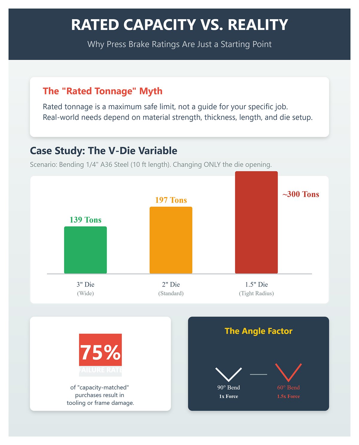
That’s why under‑rated brakes often wear out or fail well ahead of expectation. Industry data shows that nearly three‑quarters of “capacity‑matched” purchases end up with tooling damage or frame stress once operators move beyond the mild test material—forming harder alloys, tighter bends, or smaller radii than the lab assumed. A 90‑ton press brake rated for standard 90° bends might deflect or stall at 60°, since required tonnage can jump roughly 1.5× as the bend angle tightens. The only reliable number is the one you calculate based on your actual material, angle, and die configuration. Without that, “rated tonnage” is just a marketing highlight—accurate only under perfect and rarely repeated conditions.
At first glance, a “10‑foot” press brake appears to offer an uninterrupted workspace. In reality, each side frame consumes close to a foot of usable length, and the machine’s throat depth—the span from the ram’s centerline to the inner wall of the frame—dictates how far a part can protrude before hitting an obstruction. Once you account for this frame thickness, that so‑called 10‑foot bed usually delivers closer to 8 feet of genuine bending capacity.
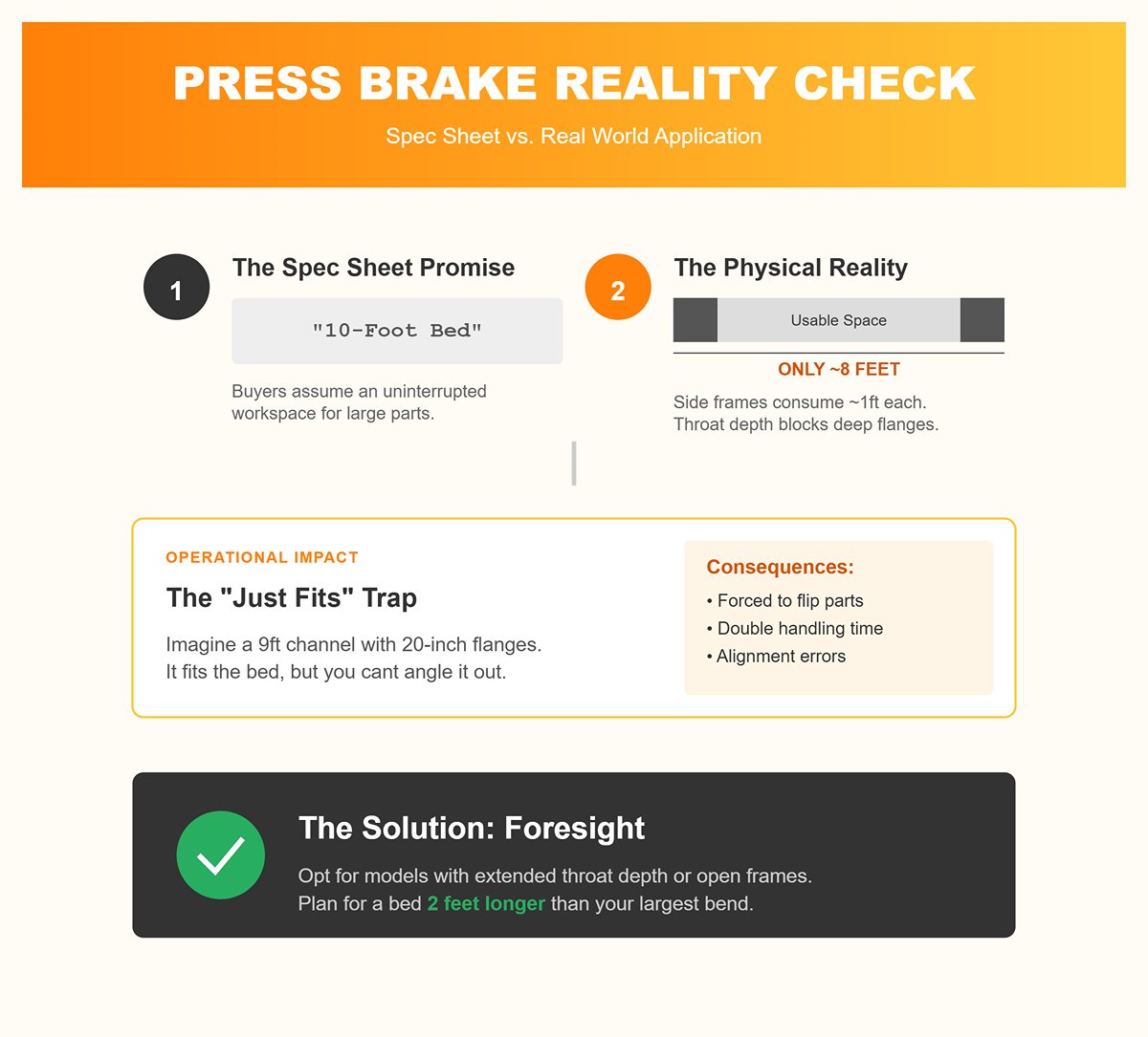
Imagine trying to form a 9‑foot channel with flanges 20 inches deep. The tooling might fit fine, but the moment you angle the part to clear a flange, the frame blocks your movement. The workaround—flipping the part or bending from the opposite end—doubles handling time and creates alignment challenges. Many buyers of used equipment only find this out after the machine arrives, when their “capacity match” forces them to wrestle beams at uncomfortable angles. The fix is foresight: opt for open‑frame designs or models with extended throat depth to maintain access, while closed‑frame machines sacrifice reach for added rigidity. If your operation involves large box sections, plan on a bed at least two feet longer than your largest bend to keep workflow efficient.
Roughly 30% of “it just fits” purchases overlook the real‑world loss of 20–25% in usable length. A spec sheet may say “10 feet,” but your parts don’t care about marketing—what matters is whether they actually clear the frame.
Even with the right tonnage and reach, there’s another critical bottleneck: can you remove the finished piece after the bend? Daylight refers to the vertical opening between the ram and bed when the brake is fully open, while stroke is the total travel distance of the ram. Together, they dictate how easily you can free a component from under the tooling. Insufficient daylight means tall flanges get stuck beneath the ram; limited stroke forces you to wrestle every part out by hand.
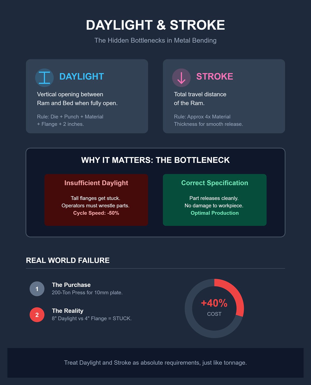
A quick guideline: daylight should exceed the combined height of the die, punch, material thickness, and finished flange by at least two inches. Stroke should be about four times the material thickness to allow smooth release. For example, bending a 6‑millimeter stainless steel plate into a tall‑flange channel calls for roughly 10 inches of stroke. Yet many “heavy‑duty” machines fall short with just 8 inches of daylight, trapping larger parts until operators tilt or force them free—cutting cycle speed in half and increasing the risk of damaging the workpiece.
One fabricator found out the hard way: on paper, a 200‑ton press brake looked ideal for 10‑millimeter plate work, but production exposed the flaw. With only 8 inches of daylight, the machine couldn’t clear 4‑inch flanges, forcing the team to rely on costly adapters that still didn’t fully solve the issue. Ultimately, they had to replace the entire unit—an upgrade that drove the total project cost up by 40%.
To avoid the same costly mistake, treat daylight and stroke as absolute requirements—just as critical as tonnage or bed length. If a press brake can’t release your part cleanly, it’s not a working brake at all—it’s just an overpriced vise.
Whenever specs and marketing claims seem to align perfectly, it’s worth asking: perfection for whom—the manufacturer or you? True productivity doesn’t come from the numbers on the nameplate, but from the hidden geometry, clearances, and depths that give those numbers meaning. Recognizing that distinction is the first step toward buying a press brake that works with physics, not against it.
Most resources treat air‑bending tonnage as a simple chart lookup, but the real advantage comes from calculating it yourself using your material properties and tooling. Air‑bend force depends on three controllable factors: tensile strength, thickness, and V‑opening. A practical production‑grade formula is: tons per foot ≈ C × (tensile strength in ksi) × material thickness (in inches) × (thickness ÷ V‑opening). Use C ≈ 1.0 as a baseline for carbon steel; adjust down to roughly 0.6 for aluminum or up to about 1.6 for stainless. Since different calculators apply slightly different constants, show a ±20% tolerance when presenting internal calculations.
Here’s a concrete example to ground the math. Suppose you’re air‑bending a 10‑foot length of A36 steel (tensile strength ≈ 70 ksi), 0.25‑inch thick, with a 1‑inch V‑opening. The calculation yields tons per foot ≈ 1.0 × 70 × 0.25 × (0.25 ÷ 1.0) = 4.375. Over 10 feet, that totals roughly 44 tons. This reflects ideal air‑bending conditions only—no allowances for production variability. A dealer promoting a 50‑ton model might insist it’s sufficient, but that’s true only in a perfect‑world scenario.
A reliable way to safeguard any purchase decision is straightforward: first, calculate the tons per foot needed for your most demanding part and full bend length. Multiply by that length, then build in safety margins. For air bending, add roughly 20–30%. If you ever switch to bottoming, plan for about four times that base tonnage—and six to ten times for coining. Finally, tack on another 10–25% if the press brake is used, aging, or runs tooling with visible wear. This single calculation prevents the all-too-common mistake where the advertised “total tonnage” looks adequate on paper but falls short once real dies and production-length flanges come into play.
The published maximum capacity reflects total cylinder force—not the usable tons per foot distributed along your actual bend length—and that’s where accuracy is usually lost. A 100‑ton press brake might coin a short sample during a demo but still fall short when air‑bending your 8‑ or 10‑foot parts using the required V‑opening. As the part length increases, the available force spreads out, reducing tons per foot. If a seller can’t show force per foot at your specific V‑die, they’re leaving out the figure that truly determines suitability.
The forming method further complicates perception. Air bending requires far less force than bottoming and dramatically less than coining. Dealers sometimes stage demos with an oversized V‑die to make the bend seem effortless, artificially lowering the tons‑per‑foot requirement and exaggerating the machine’s capacity. One cautionary example: a shop purchased a used 110‑ton brake after it easily bent a 10‑mm test strip during the demo. Their real parts were 2.5 m long and used a smaller V‑opening. Once in production, the brake under‑bent every piece, forcing costly tool replacements and a crowning retrofit—spending more overall than if they’d purchased the correct capacity from the outset.
Capacity ratings also presume a factory‑fresh press with perfect hydraulics and a rigid, undistorted frame. A decade‑old unit with worn seals or uneven Y‑axis synchronization delivers less consistent pressure and increased angular drift—none of which appears in a simple tonnage spec. Buyers focused solely on maximum force overlook the key question: How much usable force can this specific machine deliver per foot at the V‑opening my parts actually require?
Springback is the hidden toll on your tonnage. Tougher materials like stainless steel or high-strength alloys tend to snap back more forcefully after bending, often requiring 10–25% more forming energy—or even a second bend—to achieve the specified angle. Thin components with long flanges relative to their thickness amplify this problem. Modern press brakes with precise Y1/Y2 axis control and computerized crowning consistently offset springback. In contrast, older machines using mechanical crowning or slow-response valves fall short, leading to angle drift of several degrees from the machine’s center to the ends over a full shift, no matter how skilled the operator.
This variability quickly turns into a financial pain point, not just a bending challenge. At five minutes of rework per part, producing 200 parts a month at $60 per hour translates to over $1,000 lost in labor costs alone. Add in scrap rates or the expense of installing a crowning retrofit, and the impact escalates. Stainless steel—with its roughly 1.6× higher tonnage requirement than mild steel—exposes these shortcomings most rapidly: specifications that look achievable on paper often prove impossible in real-world production without extra tonnage or switch to coining.
Overlooking springback is one of the main reasons used machines disappoint buyers. The stated tonnage might seem sufficient, but uneven bed deflection or sluggish hydraulics force operators into over-bending and re-bending parts. That extra forming energy was never part of the original capacity rating, and the shortfall becomes apparent only after installation.
By calculating tonnage based on tensile strength and V‑opening, insisting on usable tons per foot, and factoring in the springback allowance, you transform a vague specification into a concrete performance requirement. This preparation enables you to enter dealer negotiations armed with a set number the machine must reliably achieve—rather than leaving room for the dealer to define it.
When sheer force and versatility are paramount, hydraulic press brakes still set the benchmark. Powered by fluid-driven rams, they maintain full tonnage throughout the stroke, enabling them to bend thick structural steel (8–20 mm) without slowing down. For demanding projects—like forming 12 mm stainless brackets or wide beam flanges—hydraulics can outperform comparable electric models by 30–50% in capacity. They also handle mixed material thicknesses in the same production run with ease. This flexibility stems from the nature of hydraulic pressure, which can be instantly adjusted to match the material’s resistance. As a result, tooling changes or inconsistent stock rarely require recalibrating for motor load limits.
Yet these advantages come with trade-offs. Hydraulic systems keep their pumps running continuously—even between bends—drawing two to three times more energy than servo-driven designs. Over the course of a year, a moderately used 100-ton unit can rack up an additional $5,000 in electricity costs. Maintenance adds to the expense: oil changes, leak repairs, and valve replacements can consume 10–15% of annual machine availability. Most mid-range models incur $5–6K annually in service costs. High-volume operations intensify the impact—over 200 bends per hour can generate heat that pushes ram accuracy from ±0.05 mm to ±0.2 mm in just 50 cycles, leading to costly rework. The pump’s constant noise often signals wear before a breakdown, but still means lost production time.
Hydraulic models remain the clear choice for low-output, heavy-duty fabrication where the workload is minimal, materials are robust, and electrics command a $50K+ premium without delivering the required force. With diligent upkeep and complete service records, they typically preserve around 20% more resale value than average.
Servo-electric press brakes shine when working with light- to medium-gauge metals, offering precision and speed in equal measure. Driven by ball screws or belt mechanisms, they achieve repeatability of ±0.01 mm and operate up to 30% faster than hydraulics. Since the motors run only during bending, not while idling, they cut energy consumption by 60–70% compared to hydraulic systems. For a medium-volume shop logging around 500 hours annually, that means $2–4K in energy savings each year.
Although the initial investment is higher—typically $120K–$180K for a 100-ton electric press brake versus $80K–$120K for a hydraulic model—the payback period is often short. Savings from reduced energy use and minimal maintenance (no oil changes, pump replacements, or valve wear) can offset the difference within about 18 to 24 months:
| Factor | Electric Cost | Hydraulic Cost | Break-even |
|---|---|---|---|
| Purchase (100-ton) | $120K–$180K | $80K–$120K | N/A |
| Energy/Year (medium shop) | $3K | $8K | 18 months |
| Maintenance/Year | $2K | $6K | 12 months |
| Cycles/Hour | 25–35 | 15–25 | Volume leader |
Electric systems also reduce shop-floor noise by roughly 15 dB, eliminate oil leaks, and decrease operator fatigue by removing hydraulic pump vibrations. In precision-sensitive work, a smaller electric machine—say an 80-ton model—can outperform a larger hydraulic when forming shallow flanges under 100 mm, minimizing costly springback adjustments.
However, limitations exist. Servo motor performance drops sharply beyond 200 tons, making electric units impractical for steel thicker than about 10 mm. For shops working within a sub-$100K budget or regularly handling heavy-gauge materials, electric press brakes may simply lack the muscle their operations demand.
Servo-hydraulic hybrids are tailored for manufacturers balancing the need for high tonnage with faster throughput. In these systems, servo motors drive the hydraulic pumps only during bending, delivering 30–50% energy savings over conventional hydraulics while retaining 300+ ton capabilities. True hybrid designs feature dual-circuit hydraulic tanks—one per cylinder—allowing independent ram control. This setup distributes load more efficiently, increases forming speed by up to 25%, and eliminates energy waste from idling the entire system.
For mid-volume facilities performing 300–800 bends daily across mixed materials, hybrids strike the ideal balance. They sustain ±0.05° angle accuracy over 10-foot beds using servo-controlled crowning feedback, cut oil consumption by about 50%, and run roughly 40% quieter than traditional hydraulics. For example, an automotive parts maker bending both 4 mm panel enclosures and 150-ton frames can achieve a two-year return on a $140K hybrid compared to a $100K hydraulic once energy savings and productivity gains are included.
Buyer beware: not all machines marketed as “hybrids” truly fit the definition. Some brands simply add an inverter to regulate pump speed, producing only about a 10% efficiency gain. Without a genuine dual-circuit design, their advertised precision and energy savings are often exaggerated. A legitimate hybrid is tailored for shops that rely on hydraulic force for part of the workday but also want the speed, accuracy, and lower operating costs needed for lighter production runs.
Selecting between hydraulic, electric, and hybrid systems isn’t about chasing the latest technology or the highest tonnage figures—it’s about aligning the drive mechanism with the physics and economics of your real production needs. Energy consumption, maintenance routines, and precision capabilities vary widely across machine types, and your investment will make sense only when those characteristics suit your material range and cycle requirements.
CNC Controls: The Feature That Can Become Your Shop’s Competitive Edge—or Sit Idle
“Orphaned Technology”: Steering Clear of CNC controllers without manufacturer backup. Many buyers zero in on tonnage, speed, and frame rigidity, but the controller is the part most likely to become outdated long before the rest of the machine. This is where shops often undermine productivity without realizing it: they take on a controller that the OEM has stopped supporting, leading to awkward workarounds, extended repair delays, and eventual retrofit costs that wipe out any savings from buying second-hand.
Models like the Delem DA‑41T or ESA S530 can run basic 2–4 axis operations adequately, but once firmware support ends—typically after 8–10 years—they won’t be able to load updated tooling databases, integrate modern safety standards, or receive essential operating system patches. Cybelec’s CybTouch 8 faces similar issues; many European manufacturers have shifted their support toward newer mid-range products, leaving legacy systems without language pack updates or collision-prevention fixes. Some shops report having to wait six to twelve months to repair out-of-production ESA S600 units from pre‑2018.
One mid-sized fabrication shop found this out the hard way: a used press brake equipped with a 12-year-old Delem DA‑42T seemed like a steal until Windows 7 support was discontinued. Once that happened, the controller couldn’t run any updated software, forcing a full retrofit that cost $15,000 and a week of lost production. The issue wasn’t the machine—it was the controller’s outdated software ecosystem.
A quick pre-purchase audit can prevent problems like these. Always request:
Any Delem unit earlier than the DA‑53T/58T or ESA model below the S640+—especially pre‑2020 builds—faces a high risk of losing manufacturer support. A press brake with unsupported hydraulics can still be serviced by a skilled technician, but one with obsolete software becomes dead weight until a compatible controller is sourced.
Offline Programming: Why It Matters More Than Touchscreen Size A large touchscreen might look impressive on a showroom floor, but it doesn’t drive productivity—offline programming does.
Offline‑capable systems such as the Delem DA‑69T or DA‑66T enable programmers to design complete bending sequences, run 3D simulations, and check for tooling collisions on a PC while the press brake continues operating. This process typically reduces setup time by 40–60% on complex jobs. For shops managing machines with six or more axes, the benefits are transformational: fewer operator errors, higher throughput, and smoother transitions between shifts.
By comparison, on‑machine editing can slow everything down. A 15‑inch screen like that on the ESA S640 may look impressive, but without offline export capability, every program adjustment requires operators to gather around the brake. Those live edits stop production cold, turning the machine into a bottleneck. A 10.1‑inch Delem DA‑53T panel is more than enough for simple 2D jobs, but once you need 3D simulation or multi‑station setups, the lack of offline programming quickly limits productivity.
Real-world data supports this. Shops using offline‑enabled controls report about 25% fewer operator errors on multi‑axis bending operations. A single programmer working at a desktop can create hundreds of part programs per week, leaving the press brake free for actual production rather than serving as a programming terminal.
Offline functionality beats screen size because it changes how you work. A bigger display may improve visibility, but offline programming eliminates idle time altogether.
If your operators don’t actually use the control interface, your investment goes to waste. A premium controller only delivers value when its features are put to work. Many shops unintentionally overspend—choosing advanced systems loaded with deep menu structures—only to see operators abandon them as soon as production gets hectic, defaulting to manual overrides or basic operating modes.
Delem’s DA‑66T and DA‑69T controls dominate the market for one clear reason: operators can move from setup to production with just a few quick taps. Most reach around 90–95 percent proficiency within two days. By contrast, Cybelec’s Modeva and similar professional-grade interfaces often demand a week or more of training, making them less practical for shops facing frequent staff turnover or varying skill levels.
ESA’s S640 and S875W systems provide exceptional flexibility—allowing custom PLC logic, fully reconfigurable HMI screens, and control of dozens of axes—but that same power can overwhelm less experienced operators. Field data shows that in lower-skill environments, up to 30 percent of the system’s capacity goes unused because operators bypass 3D tools and rely instead on manual adjustments.
Even the hardware layout plays a crucial role. In dusty or gloved environments, many shops prefer button-based controls such as the DA‑65R, which minimize touchscreen errors and unintended inputs. One fabrication line regained roughly 15 productive hours per week after replacing a failing DA‑42T touch panel with a button‑driven interface during a retrofit.
A simple test can reveal whether the control suits your team: hand your least tech‑confident operator a 10‑bend sequence. If they revert to manual X or R axis adjustments, the interface is too complex for your workforce. In that case, a streamlined Delem system with intuitive axis synchronization will produce more consistent results than a feature‑rich controller that no one uses to its full capacity.
A controller can be either the most productive tool on your press brake or the priciest accessory gathering dust. Matching the system’s capability to your operators’ skill level ensures you get the performance you paid for.
Many buyers mistakenly believe press brake tooling is interchangeable—a costly misconception. In practice, the tang’s profile dictates the entire tooling ecosystem that follows. American‑style tooling, identifiable by its narrow 0.50‑inch (12.7 mm) tang, was created for quick, manual changes to minimize downtime in general fabrication environments. It performs well for repetitive work within generous tolerances, but this convenience comes at the expense of sustained precision. Every change slightly wears the clamp interface; after only a dozen setup cycles, bend accuracy can shift by 0.01 inch—enough to render aerospace or electronics components out of spec.
European‑style tooling takes a fundamentally different route. Its wider 13 mm tang, combined with side grooves, locks securely into wedge clamps, enabling highly repeatable alignment with tolerances as tight as 0.0004 inch. These systems work seamlessly with CNC brakes that require precise angular feedback. The catch: once you invest in a press brake built for one style, you’re locked into that format. An American‑style brake won’t fit European tooling without specialized adapters—and those adapters change forming geometry, reference heights, and even load capacity ratings.
The unpleasant surprise often comes when a used “turn‑key” press brake arrives with tooling that doesn’t match your machine. Roughly 70 % of pre‑owned American‑style units marketed as “tool‑ready” include heavily worn punches incompatible with European‑style clamps. That mismatch can bring your first production run to a standstill, waiting weeks for adapters or replacement punches that may cost nearly as much as your initial down payment. This isn’t a later upgrade choice—it’s a foundational platform decision made on day one.
Online ads often boast about “1,500 lbs of included tooling,” but sheer weight is irrelevant if the steel can’t withstand real‑world use. Genuine production‑grade tooling is hardened to at least HRC 50; anything below HRC 45 is little more than shop decoration. Softer tools can deform after only a few hundred bends of 6 mm mild steel, rounding their edges and throwing off angles—leading to costly rework. In the end, buyers pay to ship what amounts to scrap metal.
Before shipment or on-site inspection, confirm the tang width and die hardness. Request a material certification from the seller, or at least a hardness reading taken from the tip of one punch. Check that all sections are consistent in length—mismatched 4-inch pieces won’t evenly distribute force across a 3‑meter bed. A genuine, work-ready set should include sections of at least 300 mm, enabling you to run a low-pressure alignment test at about 10–15 % of the brake’s rated tonnage. If the points fail to align or you spot hairline cracks in the die’s valley, treat the “included” tooling as destined for scrap.
Industry refurbishers tracking over 200 installations report that roughly 40 % of bundled punches and dies end up discarded within the first 90 days due to improper hardness or flawed geometry. A quick on-the-floor test can save time: bend a sample from your own production run to 90°. If the punch radius shifts more than 0.5 mm or begins flaking, the tooling is unusable. Replacing a hardened 3‑meter set will immediately add $2,500 to $4,000 to your acquisition costs.
Adapters may look like a cost‑friendly compromise—keeping your current punches while changing clamping styles—but the numbers often disprove the assumption. Converting an American‑style brake to run European tooling means purchasing holders priced between $2,000 and $4,000 each, plus about $1,500 in installation labor. Outfitting an entire 3‑meter bed can consume $10,000 to $20,000 before you even produce your first bend.
Beyond the expense, adapters reduce performance. Acting as an intermediary layer, they flex under load, cutting available tonnage by 20–30 %. A 100‑ton press brake effectively operates as a 70‑ton unit, forcing slower bending speeds to avoid fractures. For shops working stainless steel or plate over 3 mm thick, this drop directly impacts productivity and can cause inconsistent angles along extended flanges.
Factoring in total ownership costs, replacing tooling outright is often the more economical move. Precision European tooling for a standard 3‑meter brake typically costs $8,000 to $12,000—less than the combined expense of adapters and ongoing upkeep. Adapters typically wear out about twice as quickly and may void manufacturer warranties by altering how loads are transmitted.
| Switch Scenario | Adapter Cost (Full Setup) | Tonnage Reduction | Extra Annual Maintenance | Break‑Even vs. Full Tool Replacement |
|---|---|---|---|---|
| American → Euro (3 m bed) | $10k–$15k | 20–25% decrease | $2k/year | ≈ 18 months (high‑volume use) |
| Euro → American | $6k–$10k | 10–15% decrease | $1.5k/year | ≈ 12 months (lower‑precision work) |
| Custom hybrid holders | $15k–$25k | none | $3k/year | Never — only for specialized applications |
One shop’s experience demonstrates the hidden cost of using adapters. After modifying a second‑hand 150‑ton American brake with European‑style clamps to suit precision aluminum jobs, operators began battling a persistent 0.2° angle drift within half a year. In the end, they abandoned the adapters and invested in full‑height Euro punches instead. The combined expense ended up doubling their tooling budget and set production back by three months.
The takeaway isn’t that European tooling is always better than American — it’s that you must make an informed decision from the start. Your choice of tooling standard shapes every future investment: dies, holders, crowning systems, even the layout of your storage racks. Overlooking this alignment can turn a bargain‑priced press brake into a costly mistake, requiring five‑figure corrections before your first production job even begins.
Many buyers rely on photos or technical specs to judge a press brake’s condition, but the most telling evidence is a real‑time, full‑length test bend. Ideally, this should be done with your own sample part or with tooling identical to what you plan to use. Have the operator feed material across the full width of the bed from left to right, with the camera capturing the bent flange clearly at each stage. This will reveal angle consistency and show whether the crowning or compensation system is working evenly across the bed.
Ask for immediate proof: instruct the operator to measure and announce the bend angle or flange height at three points — left end, center, and right end — using a clearly visible angle gauge or calipers. If these measurements fall outside your tolerances (for example, over ±0.1° deviation for precision work or ±0.5 mm variation in flange length), it’s a clear sign of a failing crowning system, worn bed, or misaligned ram. These flaws are expensive to fix, making the test bend your go‑no‑go checkpoint before committing to shipment.
Under load, hydraulic noise can expose issues invisible to the eye. With the workpiece engaged and the ram maintaining pressure, instruct the operator to bring the camera close to the pump enclosure and side frames. Learn to tell apart the smooth, steady hum of a well‑functioning hydraulic system from the sustained, high‑frequency whine that signals trouble—such as scored pump gears, fluid line cavitation, or failing proportional valves. Harsh grinding or rhythmic pulsing noises suggest worn bearings or fluid flow restrictions, problems that will eventually translate into uneven bending force and unpredictable angle variation.
If possible, examine the hydraulic oil condition—ask the seller to briefly show the sight glass. A milky appearance indicates water contamination, while dark oil implies thermal breakdown. Both scenarios are expensive to fix and are early warning signs of impending pump or valve failure. Ignoring these auditory and fluid cues is one of the fastest ways to end up with a machine that looks sound yet suffers from escalating downtime and lost productivity.
Repeatability is the lifeblood of a press brake. Both the backgauge—the moving fence that positions your material—and the Y‑axes responsible for vertical ram movement must consistently hit their programmed positions cycle after cycle. Ask for three identical bends in succession, using the same material and tooling setup. Have the operator keep the camera trained on the controller display throughout, so you can monitor the position readouts as each cycle finishes.
Then demand hands‑on verification: measure flange lengths or offsets on the finished pieces from each cycle against your allowed tolerances. If the controller’s position readings drift or part dimensions vary by more than ±0.05 mm for high‑precision work (or ±0.1–0.2 mm for standard fabrication), the culprit might be worn linear guides, loosened backgauge assemblies, or poorly tuned servo drives. These flaws steadily undermine productivity, especially in multi‑bend programs where small inaccuracies add up quickly.
When asking for a 10‑minute inspection video, spell out each step to avoid vague or incomplete content:
Your message to the seller should be unmistakable: “The footage must confirm that my sample part meets tolerance at all three measurement points, that the backgauge/Y position repeats within specification over three consecutive cycles, and that hydraulics operate without high‑pitched or irregular noise under load. Any deviation is grounds for rejecting the shipment or renegotiating the price with a defined service commitment.”
By insisting on concrete proof within a tight timeframe, you remove uncertainty and compel the seller to demonstrate the machine’s true capability under working conditions. This straightforward inspection method reveals issues such as poor tooling fit, pump wear, repeatability flaws, and alignment errors before you spend thousands on freight—making it one of the most critical steps in evaluating a press brake.
The inspection video shows what the seller can demonstrate. The next step is learning what the machine will require from your facility, your electricians, and your budget the moment it arrives. This is where transactions that seem flawless on video often fall apart in practice.
Buying a press brake isn’t as simple as rolling it off a truck—it’s a major structural change for your shop. High-tonnage frames act like giant tuning forks, and if they aren’t seated on a properly engineered foundation, vibration will turn accurate bends into inconsistent angles and wear out the frame far faster. For a 10-foot, 100-ton unit, just the concrete work can run $10,000 to $50,000. The most overlooked—and most important—question is: “Exactly how thick does the slab need to be for this model?” If the seller can’t give you both a measurement and a diagram, you’ve just discovered your first hidden expense.
Getting a 20–40-ton machine through a standard doorway is pure fantasy unless you’re prepared to dismantle key components. Crane services, certified riggers, post-install leveling, and prepping ventilation for servos typically add another $5,000–$15,000. Shops that expect a simple plug-and-play installation quickly learn that hydraulic tanks and three-phase panels aren’t swayed by optimism; converting to 460V power or upgrading to dust-free ventilation can easily tack on an extra $2,000–$8,000.
One shop owner recounted losing half a day of paid plasma cutting time trying to “just get the floor ready.” That downtime doubled the actual installation cost. The story resonates because it reveals the real trap: the first 90 days don’t just drain your budget—they sap your momentum. The least expensive moment in a press brake’s life is the day you sign the purchase order.
Used machines promise instant gratification with tags like “available now,” “ready to run,” or “in stock.” But the numbers tilt the wrong way as soon as you put the wrong machine into full production cycles. A brand-new 140-ton CNC brake might take 20–45 days to arrive, yet over three years it’s typically 15–30% cheaper than so-called bargain used machines already burdened with tired hydraulic pumps, inaccurate backgauges, and crowning systems worn past their prime.
Hydraulic pumps approaching the 10,000-hour mark fail with predictable regularity. That subtle 0.5 mm backgauge drift you spotted in a video can translate into a 20–40% productivity loss once actual parts are loaded. One shop spent $80k on a used brake, only to rack up more than $60k in repairs within the first 90 days. Another kept topping off oil on a “great deal” Wysong until the math was undeniable: a new build would have saved them $25k annually in unscheduled downtime.
It may feel counterintuitive, but the numbers stay consistent: a $150k new unit plus $15k for installation nearly always outperforms an $80k used one with $50k in repairs once you factor in the real cost of uptime. The machine that’s “available now” usually has that status for a reason—its last owner already paid dearly to understand this equation.
Print this list and keep it beside your notes. If two boxes turn red, walk away. At that point, you’re not buying steel—you’re buying certainty.
There’s one question that cuts through every sales pitch: “Run my part ten times under load and send me the video along with a three‑year cost breakdown by end of day.” Vendors who can deliver that are worth your trust. Those who can’t have already given you your answer.
Which brings you back to that first moment staring at the glossy online photos—the truth that the cheapest press brake is the one that never makes it onto your shop floor.


