
You can nail the angle and still lose your job on the very first bend—because the mistake that hurts people usually happens before the metal ever reaches the die. Most incidents (and most “mystery scrap”) start with an untested control, a hand drifting into a no-go zone, or a booby trap the previous shift quietly left behind. This 60-second reset closes that gap: it’s quick enough to do on every setup, and strict enough to keep you out of the incident log.
Locate the E-stop (emergency stop) with your eyes first, then your hand—don’t assume you’ll “remember” in a panic. Press brakes vary: the button may be on the pendant, the frame, or both. If the guard around it is cracked, treat it as a defect, not cosmetic damage.
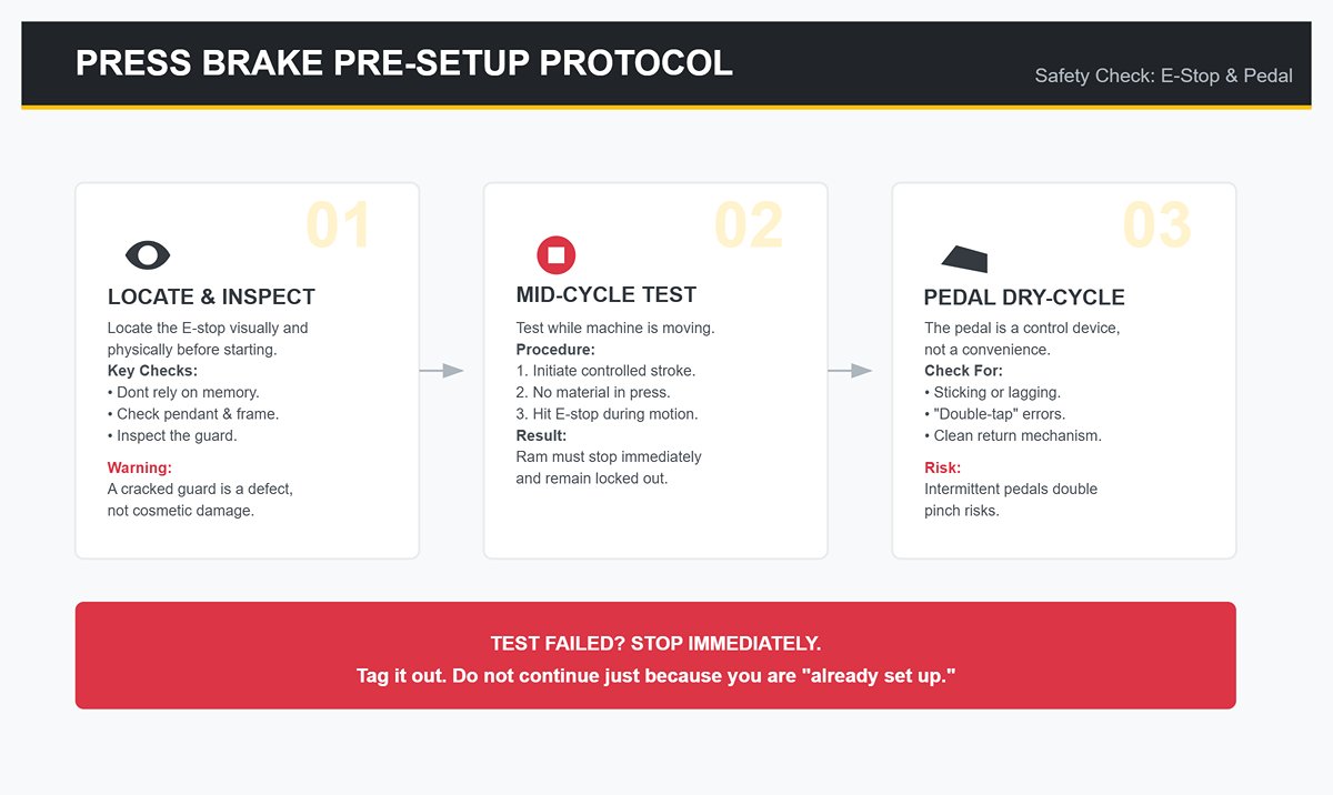
Test the E-stop while the machine is moving. In many shops, the minimum standard is a mid-cycle stop test: initiate a controlled stroke (no material) and hit the E-stop with the ram in motion. The ram should stop immediately and remain locked out until reset. Unions and insurers consistently cite untested controls as a major driver of claims—operators skip this because it “feels redundant,” right up until a sticky valve or wiring fault makes it painfully relevant.
Dry-cycle the pedal. A foot pedal is a control device, not a convenience. Before you set tooling or line up a part, dry-cycle the machine to confirm the pedal returns cleanly and doesn’t stick, lag, or “double-tap.” German-style apprenticeship programs even drill simulated dead-pedal failures on hydraulic valves for one reason: an intermittent pedal doubles pinch risk because you’ll instinctively reach in to “fix” what you think is a positioning issue.
If either test fails, stop. Tag it out. The fastest way to become the shop’s cautionary tale is to keep going because you’re “already set up.”
A press brake’s hazard isn’t theoretical—it’s only a few inches wide, and it’s exactly where your hands naturally want to be. A pinch point is any spot where a moving surface (ram/tooling) approaches a fixed surface (die/bed/backgauge), creating a crush zone.
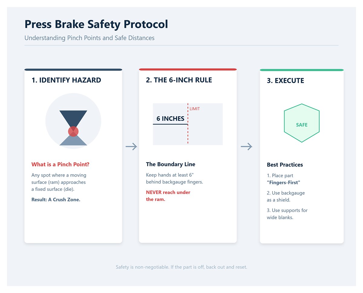
The rule in NIMS-style certification labs is simple and blunt: keep your hands at least 6 inches behind the backgauge fingers during approach. Those fingers (the small stops you push the part against) aren’t handles—they’re your boundary line. Let your fingertips creep past them and you’re in the zone where a surprise stroke, a bumped pedal, or a control fault can become life-changing in an instant.
Never reach under the ram or between the tooling—ever. Not to “nudge” a flange. Not to “catch” a slip. If the part is off, back out, reset it, and re-approach.
Real-world shop audits consistently find that poor placement before the bend accounts for a big share of scrap. The fix is unglamorous but reliable: place the part “fingers-first.” Set the sheet against the backgauge with your hands behind that line, let the gauge act like a shield, and only then initiate the stroke.
If you need to support a wide blank, use proper supports or a second person—don’t use your forearms as material-handling equipment.
“Whip up” is the rebound/snap of the sheet as the bend forms—especially in air bending, where the punch doesn’t bottom out in the die. That stored energy can pop a 14-gauge sheet up a couple of inches fast enough to hit your jaw, throat, or safety glasses. The risk climbs on narrow parts, short flanges, and springy materials.
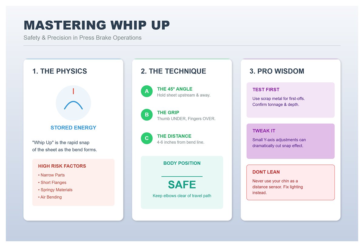
Grip and stance matter more than muscle. Approach with the sheet held at roughly a 45-degree upstream angle—slightly up and away from the tooling. Put your thumb under the edge, fingers over the top, and keep your grip 4–6 inches from the bend line: close enough to control rotation, far enough to stay out of the pinch zone. Keep your elbows clear of the travel path so the sheet can rotate without driving into your face.
When the setup is new—or the material changes—control the first bend with a scrap test piece. Shops that move people into press-brake work from laser, welding, or assembly often learn that the difference between a “pedal pusher” and an independent operator is this habit: running first-offs on junk metal to confirm tonnage, depth (Y-axis), and expected springback.
A small tweak can noticeably reduce whip. Vocational labs routinely show that dialing in a slightly different radius/depth (for example, a modest Y-axis adjustment during an air bend) can dramatically cut the snap effect.
Don’t lean over the part “to see better.” If you need a clearer view, fix the lighting, reposition the pendant, or choose a safe sightline—not your chin as a distance sensor.
Most “surprise” failures are inherited. A quick scan will catch the traps that blow up setups and hurt people—shops that track these problems routinely tie them to tens of thousands a year in lost time. Take 12 seconds and check these before you run the first real part:
This is why structured training works: new operators can get up to speed quickly on CNC brakes, but the operators who stay safe adopt the pre-bend scan and test-scrap habit. Sixty seconds is cheap. The alternative is explaining to a supervisor—and a medic—why you trusted last shift’s setup more than your own eyes.
Most press brake damage doesn’t come from “too much tonnage.” It comes from assumptions. Assuming the sheet is the gauge you think it is; assuming the V-die is “close enough”; assuming the punch is seated because it “looks straight”; assuming the backgauge is correct because the screen matches the print. Those assumptions turn a controlled forming process into a pry bar—and pry bars break tooling, crowning systems, and reputations.
Think of this ritual as the bridge between “the machine can move safely” and “the machine can make good parts without slowly tearing itself apart.”
“Gauge” isn’t a measurement—it’s a label, and it varies by material type and supplier. Add mill tolerances, coatings, and mixed drops, and “looks like 14 ga” turns into a costly guess. A few thousandths of thickness change shifts bend deduction, inside radius, and—most importantly—required tonnage. That’s how operators end up chasing angle by adjusting depth, over-penetrating the die, and blaming springback for what’s really a thickness problem.
Verify thickness with a micrometer or calipers at multiple points on the sheet (edge and center if possible). Record the actual thickness, not the nominal gauge. Confirm the material grade, too: A36 mild steel, 304 stainless, and 5052 aluminum can be the same thickness yet behave very differently in both springback and required forming force.
This isn’t academic. Operators who ignore material fundamentals burn scrap chasing springback variation; shops that invest in blueprint reading and basic shop math reliably cut these “mystery angle” failures because they stop treating thickness and grade as gut feel. Training programs that move new hires beyond “just run a bunch of parts” focus on this exact discipline because it prevents the rework loop that crushes throughput.
One technique to try: write “actual thickness” and “material type” on the job traveler before you touch the tooling. That one line stops the most common setup lie from quietly spreading through the shift.
The V-die opening (the width of the die mouth) is the lever arm of the bend. Too small and tonnage spikes, the inside radius tightens, and you start crushing die shoulders and overloading the machine. Too large and angle control gets sloppy, the inside radius grows, and flange lengths drift—especially on short legs.
For air bending (the default on most modern CNC press brakes), the safest starting point is the “8× thickness” rule: pick a V opening about eight times the material thickness. It’s not magic—it’s a proven compromise that keeps tonnage in a reasonable range while delivering a predictable inside radius and stable angle response across common materials. On thin stock, you might go to 6× for a tighter radius; on thick plate, 10×–12× may be needed to stay within tonnage limits. But if you don’t have a specific reason to deviate, 8× is the reason.
Why it matters for machine life: tonnage doesn’t spread out evenly. A narrow V concentrates force into smaller contact areas, boosting shoulder pressure and accelerating wear. Operators often try to “fix” a bad V choice by driving the ram deeper. That pushes peak tonnage right where you least want it—near the bottom of stroke—turning a setup mistake into a mechanical failure.
Structured training and certifications (NIMS, FMA, and OEM operator programs) keep circling back to this because it’s measurable and repeatable: choose the correct V-die and you avoid a chain of downstream “tweaks” that are really just compensation for the wrong geometry. Shops running four setups a day feel this immediately; the wrong die choice doesn’t just scrap parts—it drags setups toward the 60‑minute range and quietly burns tens of thousands of dollars a year in lost capacity.
A press brake isn’t a hammer—it’s a precision alignment system. The tooling has to be seated so the punch and die are coaxial (sharing the same centerline) and fully supported by the clamping surfaces. Misalignment creates side loads that chip punches, brinell die shoulders, and can even twist sectional tooling out of position.
Cleanliness comes first. Wipe down the bed, clamps, and tooling tangs. One chip trapped under a die section becomes a pivot point, forcing the punch to “find” the die under load—usually by galling one side.
Then use light pressure to seat the tools and confirm alignment before you apply full tonnage:
This “kiss-seat” step prevents a classic rookie mistake: discovering misalignment only after you’ve already hit production tonnage. Press-brake trainers often make new operators “thumb twiddlers” during setups at first, because watching an experienced operator do this light-pressure seating teaches the difference between “installed” and “aligned.” It’s also why OEM certification during commissioning matters: the habits that protect the machine are the same habits that make setups fast.
Backgauge accuracy isn’t a number on a screen; it’s a physical relationship between the sheet and the gauge fingers/stops. A backgauge that’s square, parallel, and contacted consistently produces consistent flange lengths. A backgauge that’s merely “close” produces parts that measure fine one minute and drift the next—especially once operators start “eyeballing” placement to compensate.
Set the programmed gauge position, then verify contact and squareness by feel:
This is why “just run hundreds of parts” is a poor teacher. New operators can make bends in a day on modern CNC brakes, but consistent flange control comes from disciplined setup and gauging habits—the skills that make someone independent in weeks instead of months. Shops that tie pay progression to verifiable skills like backgauge calibration and springback compensation aren’t being bureaucratic; they’re protecting throughput and the machine.
Most press-brake breakdowns chalked up to “operator error” are really math mistakes—usually an unseen tonnage spike caused by the wrong V-die. The machine doesn’t care that the cert says “mild steel” or that the part “looks thin.” It reacts to bend length, thickness, die opening, and material strength—and it will overload in a predictable way when any one of those inputs is wrong.
One technique to try: treat tonnage as a controlled variable, not a side effect. Make it a shop rule that every new setup starts with a chart (or formula) tonnage estimate, followed by a short test hit at reduced pressure with a planned ramp to full tonnage. That one habit catches most overload conditions before they show up as bed crowning, cracked tooling, or a hydraulic cycle that stalls.
Force charts exist to stop “back-of-the-napkin” guessing. Most are built around air bending (the punch doesn’t bottom the sheet into the die; the angle comes from penetration depth), assume a 1-meter bend length, and use mild steel at roughly 450 N/mm² tensile strength. They typically report force as kN per meter (or tons per foot/meter).
Use the chart like a set of coordinates: find material thickness on one axis, V-opening on the other, and read the force where they intersect. Then scale it to your actual bend length.
Example: a typical chart value for 4 mm mild steel in a 32 mm V-die (the classic “8× thickness” choice) is about 330 kN per meter. For a 2.5 m bend, multiply: 330 × 2.5 = 825 kN, or about 83 metric tons. That’s not your machine setting—it’s your estimated load.
Two adjustments keep the chart honest:
Material factor. Stainless often needs ~1.4× the force of mild steel; aluminum may be closer to ~0.7×. If your chart is based on mild steel and you’re bending 304 stainless, apply that multiplier before you assume you’re in the clear.
Capacity buffer. Charts assume ideal conditions—clean tooling, stable lubrication, correct alignment, and consistent sheet. Add a real-world buffer (often ~20%) so normal variation doesn’t push you into overload during production.
Quick chart hack (most shops miss this): if you’re torn between two V openings, start with the wider V—not the tighter one. It cuts force dramatically, and it’s far easier to tighten a radius later than to recover from an overload event.
The quickest way to exceed a press brake’s tonnage is to pick a V opening that’s too narrow for the material thickness. A lot of shops memorize “8× thickness” as a rule of thumb—then break it when they want a tighter inside radius. The catch is the force relationship isn’t linear—it climbs fast as the V gets smaller.
Even a basic air-bending estimate shows the pattern: force scales with thickness² and is inversely proportional to the V opening. Halve the V and you roughly double the force; in real life—tool contact, friction, and setup variation—the increase can feel even more severe.
Here’s a realistic, chart-style example: 4 mm mild steel in a 32 mm V might take about 330 kN/m. Drop to a 16 mm V, and the load can climb to ~1320 kN/m—roughly 4×. That’s the “tonnage spike”: the setup looks almost the same, but the machine is seeing a completely different load.
The bigger trap: many jobs accidentally change processes. Air bending is your baseline. Bottoming (driving the sheet deeper into the die to “lock” the angle) can take ~4× the air-bending tonnage, and coining can reach ~10×. If you “just bump it” to improve angle repeatability without recalculating, it’s easy to exceed the press brake’s rating even when the chart looked safe.
This quick risk table for 4 mm mild steel, 1 m bend shows how fast the danger ramps up:
If you need a tighter inside radius, the safer move is usually different tooling (a larger-radius punch choice, staged forming, or a controlled bottoming plan) rather than shrinking the V and hoping for the best.
| Section | Key Points | Example / Notes |
|---|---|---|
| What Happens When You Choose Too Small a V-Die (The “Tonnage Spike” Risk) | Choosing a V opening that is too narrow for the material thickness is one of the fastest ways to exceed press brake tonnage. Many shops use the “8× thickness” rule of thumb, but may break it to chase a tighter inside radius. The force increase is not linear; it rises quickly as V gets smaller. | Risk increases sharply when reducing V opening. |
| Basic air-bending relationship | Force scales with thickness² and is inversely proportional to V opening. Halving the V roughly doubles the force (and in practice can feel worse due to tool contact, friction, and setup variation). | Smaller V → higher load; thickness increase has an even stronger effect (squared). |
| Chart-style tonnage spike example | A setup can look similar while machine load changes dramatically. | 4 mm mild steel: 32 mm V ≈ 330 kN/m; 16 mm V ≈ 1320 kN/m (~4×). |
| Hidden trap: changing the forming process | Jobs may unintentionally shift from air bending to bottoming or coining. Bottoming can require ~4× air-bending tonnage; coining can reach ~10×. “Just bumping it” for repeatability without recalculating can exceed machine rating even if charts looked safe. | Air bending = baseline; bottoming ≈ 4×; coining ≈ 10×. |
| Quick risk table (4 mm mild steel, 1 m bend) | Shows how danger ramps up as V opening shrinks relative to thickness. | 12× (64 mm V): low load, very forgiving; 8× (32 mm V): standard load, manageable with margin; 6× (24 mm V): high load—watch deflection and length limits; 4× (16 mm V): critical—classic tonnage-spike territory, high crash risk. |
| Safer approach for tighter inside radius | Prefer alternative methods over shrinking V and hoping: different tooling, staged forming, or a controlled bottoming plan. | Use larger-radius punch, staged forming, or planned bottoming instead of reducing V opening too far. |
An overload usually doesn’t start with a bang. More often, it shows up as consistent mechanical symptoms—especially on long bends, where the bed and ram are under the most leverage.
Deflection (bed/ram bow). High tonnage over long lengths can make the bed and ram bow, leaving you with a different angle in the middle than at the ends. If you’re seeing angle variation across the bend line that wasn’t there on light test hits, suspect deflection. A quick check is to do a short run on scrap and measure angle consistency end-to-end; when it’s inconsistent, the root cause is often load-related before it’s tooling-related.
Slow cycling and hesitation. If the ram slows partway through the stroke—or the machine suddenly takes longer to reach depth—the hydraulic system may be running close to relief pressure. This often happens when the “mild steel” assumption is wrong (you’re actually bending higher-strength material or stainless), or when friction spikes due to dirty or galled tooling.
Stalling or creeping (stop immediately). A change in pump pitch with little ram movement, a stall near the bottom of the stroke, or axis creep/back-off between cycles are all major red flags. These signs mean the machine is at—or beyond—its usable tonnage for this setup. Continuing risks frame stress, blown seals, and broken tooling—often the most expensive “hidden” cost of choosing the wrong V.
Fast overload check (60 seconds): Run the ram with no load to confirm normal speed and sound; make one reduced-pressure test hit on scrap; listen for strain and watch for hesitation; then check angle uniformity end-to-end. If anything worsens as pressure increases, open the V (or shorten the bend length), reduce target penetration, and recalculate before you proceed.
Many operator manuals describe the first bend as a simple, binary action: press the pedal, and the ram comes down. This oversimplification is a major contributor to tool damage and inconsistent angles in fabrication shops. The actual bending process isn’t a single movement but a series of precisely controlled pressures and speeds. While the setup phase focuses on geometry, this phase is about applied physics. The machine is now active, tonnage has been calculated, and the backgauge is set. The difference between a piece of scrap and a perfect component hinges on how effectively you manage the ram’s descent and dwell time.
The most counterintuitive habit for new operators to adopt is slowing down the ram just before it makes contact with the metal. Although modern hydraulic systems allow for rapid approach speeds to maximize efficiency, maintaining full speed through the point of contact is a critical mistake. Striking the material at maximum descent speed generates “shock loading,” a phenomenon that can momentarily increase tonnage by 25-50% above calculated values. This brief overload can deflect the punch tip, accelerate die wear, and introduce unpredictable variables into the final bend angle.
Operators transitioning from basic operation to skilled setup should practice reducing the ram’s descent speed to 20-30% within the final 1-2 inches of travel (often referred to as the “mute point” on CNC controls). This slow approach serves a dual purpose. Firstly, it eliminates kinetic shock, ensuring the applied force aligns with the programmed force. Secondly, in air bending operations, it allows for visual confirmation that the material is seating correctly into the V-die. This controlled entry is essential for achieving accurate results.
Precision Practice Drill: You can demonstrate this principle using scrap material. Cycle the ram at full speed five times, observing the amount of sheet metal “whip.” Then, slow the approach to a crawl just before contact and repeat the process. Measure the variance in bend angles between the two methods. You’ll typically find that angle scatter decreases from 3° to under 1° simply by controlling the entry velocity. This visual feedback is vital for managing springback; if the ram moves too quickly, you can’t observe the material settling before it retracts, masking angle errors until the part is already unloaded.
Bottom Dead Center (BDC) refers to the exact point where the press brake ram reaches its lowest position and pauses before retracting. In air bending, this depth is what ultimately dictates the final angle. It’s a common misconception that the machine automatically knows how to achieve a 90-degree bend. In reality, the operator must precisely set the BDC based on the material’s thickness and its resistance to bending.
New operators frequently misjudge this depth, causing the punch to penetrate the V-die by an excessive 10-15%. This unintentional action can lead to “coining” the material, potentially causing cracks along the outer radius or damaging the tooling. The objective is to identify the precise depth needed to achieve the target angle after the material experiences springback. For instance, when air bending 14-gauge mild steel, a stroke depth of 11-12mm might be necessary for a standard radius bend, whereas achieving an acute angle through bottoming requires a shallower depth of 6.5-8mm.
To accurately set this without guesswork, employ the “rule of thumb” test. Perform a dry cycle with the ram at your calculated BDC, then place a feeler gauge between the punch and the die. For air bending, this gap should approximate 0.85 times the material thickness. From this starting point, fine-tune the Y-axis depth in 0.1mm increments until the sheet makes contact without deforming.
The Importance of Dwell Time: Accurately setting the depth is only part of the process; the machine must also be programmed for the duration it holds at BDC. Without adequate dwell time – holding the ram at BDC for 0.5 to 1 second – springback can reduce the angle by 2-4 degrees on longer bends. This brief pause allows the material to stabilize. Attempting to force a 90-degree angle by driving the punch deeper instead of holding it longer (which is coining) drastically increases tonnage requirements, potentially overloading the ram.
Once the very first part is successfully bent, the machine must halt for inspection. This “first-off” check acts as a crucial gatekeeper for profitability. Shops that enforce a rigorous inspection protocol at this stage often see their first-pass yield rates improve from 90% to 95%. Conversely, approximately 80% of all batch production failures can be attributed to a first-off part that appeared acceptable visually but harbored subtle geometric flaws.
Visual inspection alone is insufficient. Variations in grain direction can cause two identical sheets to bend with up to a 2-degree difference if not precisely measured. A professional first-off inspection necessitates the use of a digital protractor for measuring the outside bend angle (tolerance of ±1°), calipers for verifying leg lengths, and a height gauge to confirm parallelism.
The Deadly Dozen Checklist:
Perform this 12-second scan on every first-off part. If any point fails, do not proceed to the batch run.
Untrained operators miss backgauge offsets on nearly 73% of first-offs, leading to uniform angle drift throughout the run. By validating these metrics immediately, you transform a warped test piece from a panic moment into a diagnostic tool. If the angle is open, adjust your BDC depth. If the legs are uneven, check your backgauge calibration. Only when the first-off survives this checklist does the production run begin.
Bad bends usually aren’t random—they have a pattern. The quickest way to diagnose the problem is to stop blindly tweaking depth and speed and instead identify the error’s “signature”: is every part off by the same amount, does it vary along the length, does the angle change after you release the pedal (springback), or do supposedly identical sheets behave differently?
Do a three-part check before you touch any settings: bend three scrap pieces from the same sheet using the same program and tooling, and label them A/B/C in the order you made them. Measure flange length and angle on each. If A, B, and C match each other but miss the print, you likely have a reference or springback issue. If they don’t match each other, you’re more likely dealing with deflection, inconsistent material orientation, or inconsistent setup pressure/positioning.
When every flange comes out consistently long or short by the same fixed amount (often 0.5–2 mm), start with the backgauge reference. The backgauge is your length datum: if the fingers aren’t actually where the control thinks they are—or the part isn’t truly seated against them—you’ll reproduce the same error perfectly on every bend.
Most common causes:
Fast proof: Measure flange length at both ends of the part. If both ends are off by the same amount, the backgauge reference is the likely culprit—not crowning, and not ram depth.
Corrective action that lasts: Build a repeatable backgauge-reference routine. Zero the gauge using a known standard (a ground spacer or verified bar), then run three scrap feeds without bending—just seat the part to the fingers and mark where it lands. If the marks repeat, your “stop” is real. If they don’t, correct finger wear, alignment, or condition. Shimming a worn finger back to spec can take less than a minute—and can save an entire batch from becoming scrap.
If the bend angle changes from the ends to the center, you’re dealing with press brake deflection. Under load, the ram and bed bow. On long beds and higher tonnage (for example, bending 1/4-inch steel across 10–12 ft), deflection can be enough to shift the bend angle by 2–3° from end to center. The part may “smile” (tighter in the middle) or “frown” (more open in the middle), depending on the setup and any compensation in use.
Key diagnostic: Measure the angle in three spots—left, center, right—on the same bend. If the center differs while flange length stays correct, your backgauge reference is fine; the machine is bending unevenly across the length.
Why it catches people off guard: Even at “moderate” tonnage, the bending moment tends to peak at midspan. On older brakes—especially those without solid ram synchronization—deflection often builds faster, so shops frequently see much worse angle variation on aging machines than on newer, synchronized systems.
How to fix it:
Simple shop test: Lay a straightedge along the formed flange and mark the contact points with chalk. If the gap varies by more than about 0.5 mm along the length on a long part, deflection is significant enough that you should adjust crowning/shimming before you start chasing depth.
If the part is correct while it’s still under load but opens up after you release it, that’s springback. In air bending, you usually have to overbend—often to ~92° to end up at 90°—because elastic recovery starts the moment pressure comes off. Springback is mainly driven by yield strength and thickness: mild steel may rebound 1–2°, stainless is commonly 3–5°, and some aluminums can be even more sensitive.
The quickest wrong assumption to kill: Thinking the programmed angle equals the final angle. The control is commanding ram position (Y-depth), not finished geometry. Two sheets at the same thickness can still spring back differently if their yield strength differs (different heat/temper, mill source, or lot).
How to dial it in without guessing: Make a scrap bend, measure after 10 seconds (springback stabilizes quickly, but not always instantly), then adjust Y-depth in small steps until the final angle repeats. Bend charts are a good starting point, but they can be off by 10–15% on cold-rolled or high-strength stock—real measurements win.
What “right” looks like: A controlled overbend—slightly acute while clamped—then a consistent relaxation to the target angle after release, part to part.
Two blanks stamped with the same material and thickness can still bend differently because of grain direction—the mill’s rolling direction. Rolling stretches the microstructure, so the sheet responds differently depending on whether you bend parallel or perpendicular to that direction. You’ll see it in springback, inside radius, and crack susceptibility.
Typical pattern: When the grain runs parallel to the bend line, springback often increases and the bend can feel “stiffer,” so the angle opens more than expected. When you bend across the grain (grain perpendicular to the bend line), you may get tighter radii—and on some alloys, a higher risk of surface cracking if the radius is too sharp.
Why it creates “mystery” angle drift: Mixed orientation within a batch—especially when parts are nested from different sheet directions—can produce 2–3° of variation even with a dialed-in setup. Some shops have scrapped entire runs because half the blanks were rotated 90° during cutting, creating consistent-but-different springback.
Production-grade fix: Mark the rolling direction on incoming sheets (many mills do this; if not, add “LD” for longitudinal direction with a marker), then control orientation through cutting and forming. When tolerances are tight, consistency beats chasing the “best” direction.
One Technique to Try (5-Minute Diagnostic): The 3×3 Bend Map
Cut three scrap strips from the same sheet, all the same width. Bend each strip once, then measure the angle at left/center/right on each strip (nine readings total). Record flange length once per strip.
Nine measurements can tell you what a single tweak never will: whether the machine, the reference, the material, or plain physics is to blame.
Most bending defects aren’t “mystery material issues”—they’re repeatable fingerprints of the first variable that’s out of place. The quickest path to a stable process is to make one change that’s both low-risk and diagnostic: either it fixes the problem, or it confirms the cause so the next adjustment is straightforward. The three defects below make up a disproportionate share of press brake scrap because they tempt operators to chase angle with depth instead of correcting radius, deflection, or surface contact conditions.
Cracks that start on the outside of the bend line (the tension side) are usually a radius issue—not a “bad sheet” issue. The most common trigger is forcing too small an inside radius by using a V-die opening that’s too narrow, or by bottoming/coining when the material (or temper) can’t tolerate the strain.
6061 aluminum is the classic trap: once you get above about 1/8″ thick, it can crack readily if you try to “make it sharp.” A reliable first move is to switch to air bending with a larger V opening—typically 8–10× material thickness—so the bend forms with a more forgiving radius (often around 1/16″ minimum without splitting, depending on tooling). If the print truly requires a tight inside radius, treat it as a process choice (different alloy/temper, a larger punch radius, or an added forming step), not something you try to force with a depth tweak at the machine.
The fix that usually works first: increase stroke depth by 0.5 mm, re-set the backgauge, and run a scrap piece at about 85% of calculated tonnage. That small depth change often shifts you out of partial bottoming and into stable air-bending, reducing peak strain in the outer fibers. It also shows whether the cracking is material-sensitivity-driven (still cracks at reduced tonnage) versus setup-driven.
Springback compensation is the second big thing people miss. If you’re aiming for 90°, you’ll often need to form to about 88° (roughly a 2° overbend) in mild steel so you land on-angle after elastic rebound—numbers consistent with the basic metallurgy covered in vocational/NIMS-style training. When operators try to “chase” the final angle by driving deeper with a tight V, they can create cracks that don’t show up right away; microcracks can open up after the part cools or sits, especially in certain stainless grades where residual stress concentrates at the bend line. A simple two-cycle scrap test—bend, inspect, wait briefly, then inspect again—catches this before it turns into a production surprise.
When a long part bows like a banana, the machine is telling you the bending force wasn’t evenly distributed along the length. Once you get past roughly 48″, ram and bed deflection become major factors; under higher loads (for example, around 50 tons total), it’s common to see 0.010–0.020″ of deflection if crowning isn’t engaged or properly calibrated. The result is different bend angles from the center to the ends—and the part “reports” that mismatch as a bow.
A quick diagnostic that sidesteps material variables is a dry run with a long, straight bar or test piece at near-zero tonnage. If the ends “lift” relative to the middle by more than about 1/16″, you’re dealing with alignment/deflection—not inconsistent sheet. From there, the 90% fix is crowning: enable auto-crowning or dial in hydraulic/mechanical crowning to add a few thousandths at center (e.g., +0.005″) so the bend angle matches from end to end.
Not every banana-shaped part is a crowning issue. Backgauge wear or mismatched finger height can make the ends contact first by around 0.015″, effectively twisting the setup into a bowed result. Leveling the backgauge fingers with a feeler gauge—or programming a slight taper stop (a progressive 0.010″ bias)—can eliminate “mystery bows” that look like deflection but are really inconsistent referencing.
A shop-floor reality that matters: a lot of “operator-caused” bows actually trace back to Y-axis drift over repeated cycles. Resetting Y-zero with a dial indicator on a schedule (for example, every 50 parts during long runs) is crude, but effective when the machine doesn’t have tighter closed-loop compensation.
Heavy die marks are a surface-contact issue, not an angle issue. Polished 304 stainless can get gouges roughly 0.003–0.005 in. deep when you run at full chart tonnage with standard V tooling. The usual culprits are bottoming/coining pressure or a die opening that’s too tight, which concentrates contact pressure into a narrow line.
Two front-line fixes solve most cases. First, reduce pressure: on air bends you can often run around 70% of chart tonnage and still hit angle by compensating with overbend. That trade—less force, more deliberate springback correction—often eliminates the “V-shadow” you can see from across the shop. Second, add a sacrificial barrier: 0.004 in. polyethylene (PE) protective film in the V-die can deliver a near zero-score finish on cosmetic parts.
Film has its own physics. It adds about 0.002 in. of interference, so you may need to bump punch depth about 0.001 in. to avoid underbending. Treat film wear like any consumable: in high-volume work, swapping it out after a few hundred strokes (about 500 as a practical, log-based rule) helps prevent “random” marks from coming back mid-run.
One technique to try: stop treating tonnage charts as permission to use maximum force. A lot of articles imply “calculate tonnage, then apply it.” For cosmetic parts or crack-prone work, flip the habit: start at the minimum tonnage that gives you stable air bending (often 60–85% of chart), then add crowning/angle compensation. If the defect improves immediately, you’ve confirmed a pressure-driven failure mode—without changing tools or material—and you’ve kept the option to tune angle with controlled overbend instead of brute-force depth.
Most shutdown advice boils down to “power off, clean up.” The real danger is stored energy: hydraulic pressure, the ram’s weight, residual electrical charge, or even a die that’s only half clamped. A press brake that appears “off” can still move with enough force to crush fingers or ruin tooling. Shutdown isn’t just about safety—it also prevents seal damage, cuts morning setup time, and protects alignment so the next shift gets consistent bends instead of a troubleshooting session.
Leaving a hydraulic press brake sitting overnight with the ram under load keeps continuous pressure on seals and valves. That constant stress speeds up seal wear, raising the odds of leaks—or a hard failure—when you start up again. The counterintuitive part is that overload sensors and relief valves don’t make this “safe.” They can bleed off slowly while the machine sits, then allow residual force to spike on startup—exactly the kind of shock that breaks components faster than a straightforward operator error.
Shutdown means taking the load off, not just stopping movement. Bring the ram to a stable, supported position as the manufacturer specifies, then fully isolate the energy source. On hydraulic machines, treat any idle period or tool change as a lockout/tagout (LOTO) situation: isolate and lock out power so the machine can’t cycle—or drop—unexpectedly. This matters because hydraulic rams can drift from valve seepage or gravity; “it’s not moving” is how hands end up in pinch points. ANSI B11.3 calls for effective safeguarding and energy control; interrupting a cycle partway is not a safe state.
Mechanical press brakes bring different risks: stored mechanical energy and brake/clutch behavior. A common practice is to park the ram at bottom-of-stroke before shutdown, then power down controls and prevent unintended actuation—use the locking pin where applicable, or remove and secure the foot pedal. Bottom-of-stroke helps reduce the chance of an unexpected descent, but it still doesn’t replace proper energy isolation.
For extended shutdowns (more than two months), don’t let the hydraulic system sit stagnant. Run the pump with no load for about 20–30 minutes each week to circulate oil and keep seals lubricated. This simple habit helps prevent dry-start damage and surfaces developing leaks while they’re still minor.
Tooling removal is where “end-of-shift shortcuts” turn into next-shift delays—or injuries. The safest sequence keeps hands out of the die space and prevents an unexpected cycle. Use the palm buttons to bring the ram down close to the lower die without hard bottoming, then switch off the operator key before loosening clamps and sliding the tooling out. That key-off step matters: residual power and control logic can trigger “ghost cycles” on restart if someone bumped a pedal or a control state was left armed. Shops that standardize “Ram Down + Key Out” cut these restart surprises dramatically, and a simple label at the control station trains new operators faster than any lecture.
Inspect while it’s still fresh. Cracked, chipped, or mushroomed punches and dies are a common cause of next-shift jams because they can shift under load, throw off alignment, and make the sheet behave unpredictably. A quick visual check now is far more valuable than discovering damage mid-run, when material and schedule pressure are at their peak.
Organization is the difference between a five-minute setup and a twenty-minute scavenger hunt. Store dies in labeled racks by V-opening size and punch radius. As a rule of thumb, many bends perform well with a V-opening around 8× material thickness—but your rack labels should reflect your actual shop standards so the next operator doesn’t “make it work” with the wrong V and introduce angle variation. For idle periods longer than two months, wrap tooling in VCI (vapor corrosion inhibitor) paper or an equivalent and protect the edges; corrosion on working surfaces changes bend consistency and speeds wear.
A press brake rarely fails without warning—it fails after the warnings go unrecorded. The operator’s log is the bridge between “something felt off” and a maintenance fix, before downtime gets expensive. Record anomalies immediately and in concrete terms: “high-pitched whine on downstroke at ~80% tonnage,” “ram coasts ~2 seconds after release,” or “clunk at bottom near left side.” Specific details let a technician reproduce the condition instead of guessing.
If the ram doesn’t stop immediately when you release the controls, treat it as urgent. Coasting points to brake wear or a control issue and should be reported and corrected before the next run. End-of-shift checks should also confirm safety response: block the light-curtain sensor (the ram must stop instantly) and test E-stops from every operator position. Any sluggish response can signal hydraulic seal wear or control-system degradation—exactly the kind of issue that turns “weird clunks” into a major ram rebuild.
A simple table makes the log practical and actionable:
| Noise Type | Likely Cause | Log + Fix |
|---|---|---|
| Whine on descent | Hydraulic cavitation | Check oil level; run a no-load cycle |
| Coast after release | Brake wear | Have a supervisor adjust the brake before the next run |
| Clunk at bottom | Die misalignment | Re-seat under light pressure; recheck clamps |
For seasonal shutdowns, document the baseline oil level and the breather’s condition (dryness/contamination). Along with weekly no-load circulation, these notes surface most seal and cavitation issues early. In dual-operator modes, also log control-timing problems: if one pedal or palm button lags, it can hide a developing brake issue—until a solo shift reveals it the hard way.